Downloaded 74 times
![OBD I & II (On Board Diagnostic)
(IJSRD/Vol. 1/Issue 5/2013/044)
All rights reserved by www.ijsrd.com 1218
1) The OBD-I and OBD –II monitoring items can be
checked by diagnostic scan tool with a standard
connector that can be connected to the vehicle
diagnostic connector which is required to be within 2
feet of the steering wheel.
2) In general, the MIL is not ON at the instance of
problem being raised, it would take few driving cycles
to indicate the MIL ON.
3) It is checked for the fault codes to determine the
problem in the system.
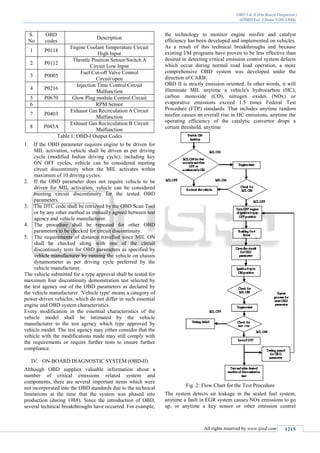
4) The DTCs for OBD implies the following:
a) EOBD fault codes consist of five characters. A
letter followed by four numbers. The letter refers to
the system being interrogated e.g. Pxxxx would
refer to the power train system and likewise B and
C for Body and Chassis respectively. The next
character would be a 0 if complies to the EOBD
standard. So it should look like P0xxx.
b) The next character would refer to the sub system.
P00xx - Fuel and Air Metering and Auxiliary
Emission Controls.
P01xx - Fuel and Air Metering.
P02xx - Fuel and Air Metering (Injector Circuit).
P03xx - Ignition System or Misfire.
P04xx - Auxiliary Emissions Controls.
P05xx - Vehicle Speed Controls and Idle Control
System.
P06xx - Computer Output Circuit.
P07xx - Transmission.
P08xx - Transmission.
The following two characters would refer
to the individual fault within each
subsystem.
5) By analyzing the code the inspector can know where
the problem is and rectifies it.
X. CONCLUSION
On-Board Diagnostics (OBD) has proven to be an effective
implementation to control the emission levels as it monitors
the emission control systems/devices and indicates any
malfunctions in the system to the owner. Many states now
use OBD-II testing instead of tailpipe testing in OBD-II
compliant vehicles. Since OBD-II stores trouble codes for
emissions equipment, the testing computer can query the
vehicle's onboard computer and verify there are no emission
related trouble codes and that the vehicle is in compliance
with emission standards for the model year it was
manufactured. Real world data has shown that the use of
OBD for inspecting vehicle emission control systems offers
many benefits to the consumer, the technician, and the
environment:
1. Accurate diagnosis that leads to effective, durable
repairs.
2. Short inspection time for the public.
3. Early vehicle maintenance opportunity, which
leads to greater fuel efficiency and reliability.
4. Incentive to car manufacturers to produce more
durable engines and emission controls.
5. Simple and affordable testing method.
6. Early detection of potential emission exceedance.
7. State-of-the-art evaporative emission detection.
REFERENCES
[1] Hassan, N.N. Dept. of Electron. Eng., NED Univ. of
Eng. & Technol., Karachi, Pakistan .
[2] The OBD-II
homepage:http://www.obdii.com/background.html
[3] Understanding your dashboard gauges:
http://www.familycar.com/classroom/ dashboard.htm
[4] PT100 Platinum Resistance Thermometers:
http://www.picotech.com/ applications/pt100.html
[5] Moshe Gray. "Interactive diagnostic system for an
automotive vehicle and method" US patent no.
5,214,582
[6] David S. Breed. "On-board vehicle diagnostic
module using pattern recognition" US Patent no.
5,809,437
[7] Fulvio Cascio t, Luca Console', Marcella
Guagliumi3, Massimo Osellal, Corso Andrea Panati2,
Sara Sottanol, Daniele Theseider Dupre. "Generating
on-board diagnostics of dynamic automotive systems
based on qualitative models" Journal: AI
Communications, Volume 12, Numbers 1-2/1999
Pages 33-43.
[8] Hu Jie, Yan Fuwu, Tian Jing, Wang Pan,
Cao Kai, "Developing PCBased Automobile
Diagnostic System Based on OBD System" 978-1-
4244-4813-5/10/$25.00 ©2010 IEEE.](https://image.slidesharecdn.com/ijsrdv1i5044-140805044600-phpapp02/85/OBD-I-II-On-Board-Diagnostic-6-320.jpg)

The document discusses On-Board Diagnostics (OBD) systems used for monitoring vehicle emissions and detecting malfunctions to aid compliance with emission control regulations, particularly in India since 2010. It outlines the workings of OBD-I and OBD-II systems, highlighting their roles in diagnosing vehicle emission-related issues, monitoring engine performance, and improving air quality by controlling harmful pollutants. The text emphasizes the technology behind internal combustion engines and the importance of efficient combustion and emissions management to mitigate environmental impacts.


![Electronic fuel injection system [EFI]](https://cdn.slidesharecdn.com/ss_thumbnails/efibilkulfinal-171227111232-thumbnail.jpg?width=640&height=640&fit=bounds)

![@&$%{<<><}{{Sensors][[[]] used in engine.ppt](https://cdn.slidesharecdn.com/ss_thumbnails/sensorsusedinefi-241005063801-504e3d07-thumbnail.jpg?width=640&height=640&fit=bounds)