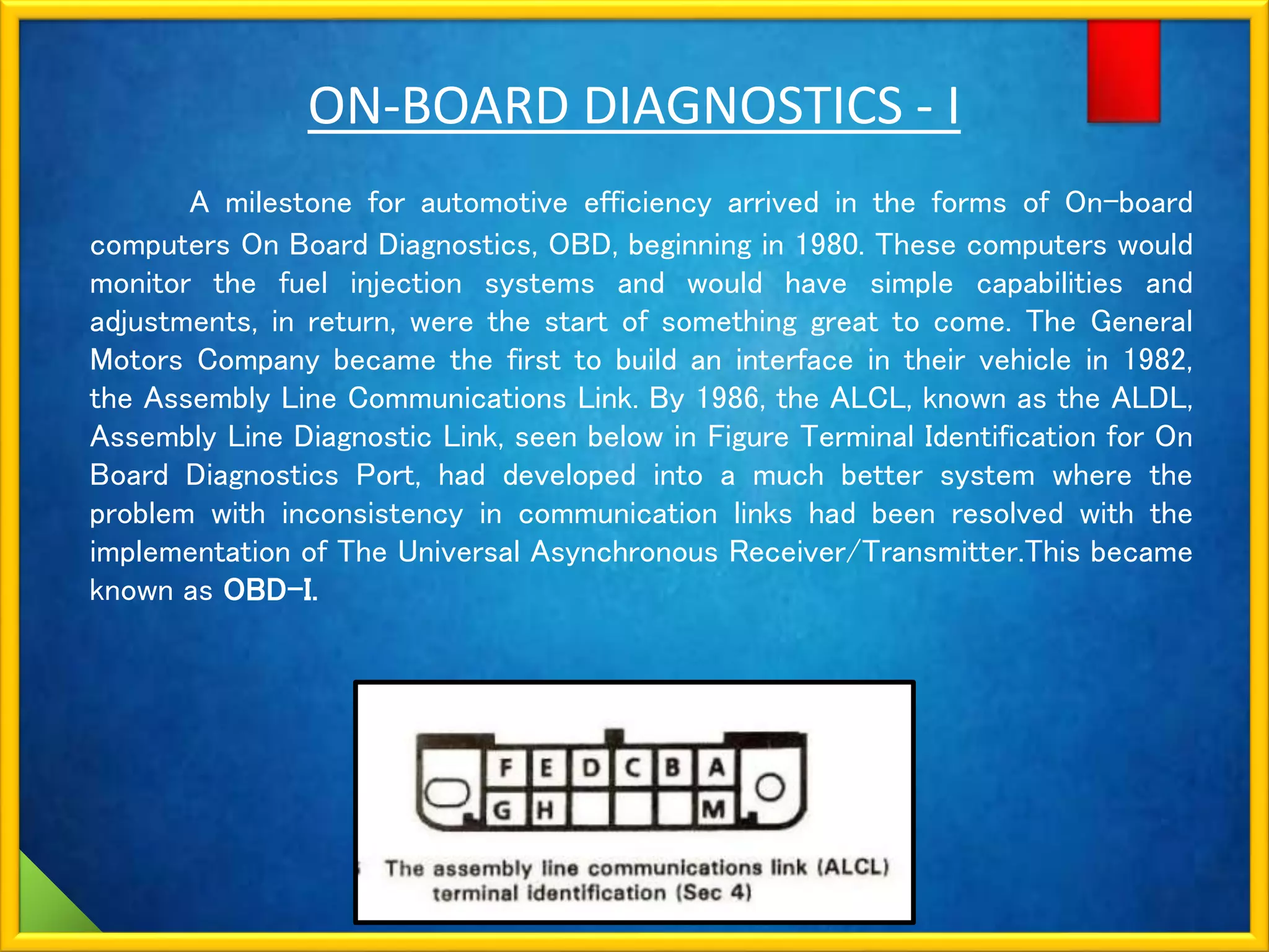
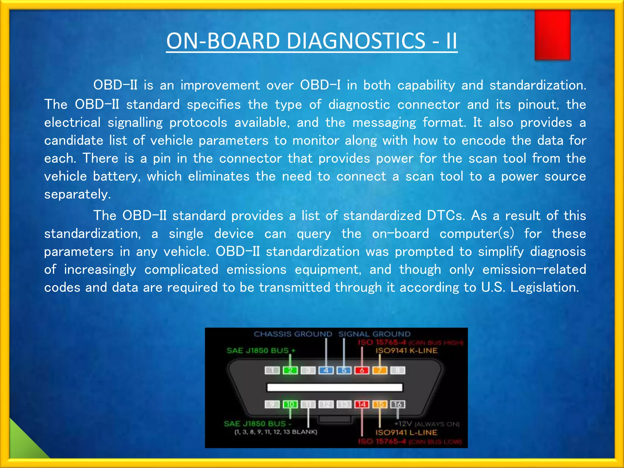
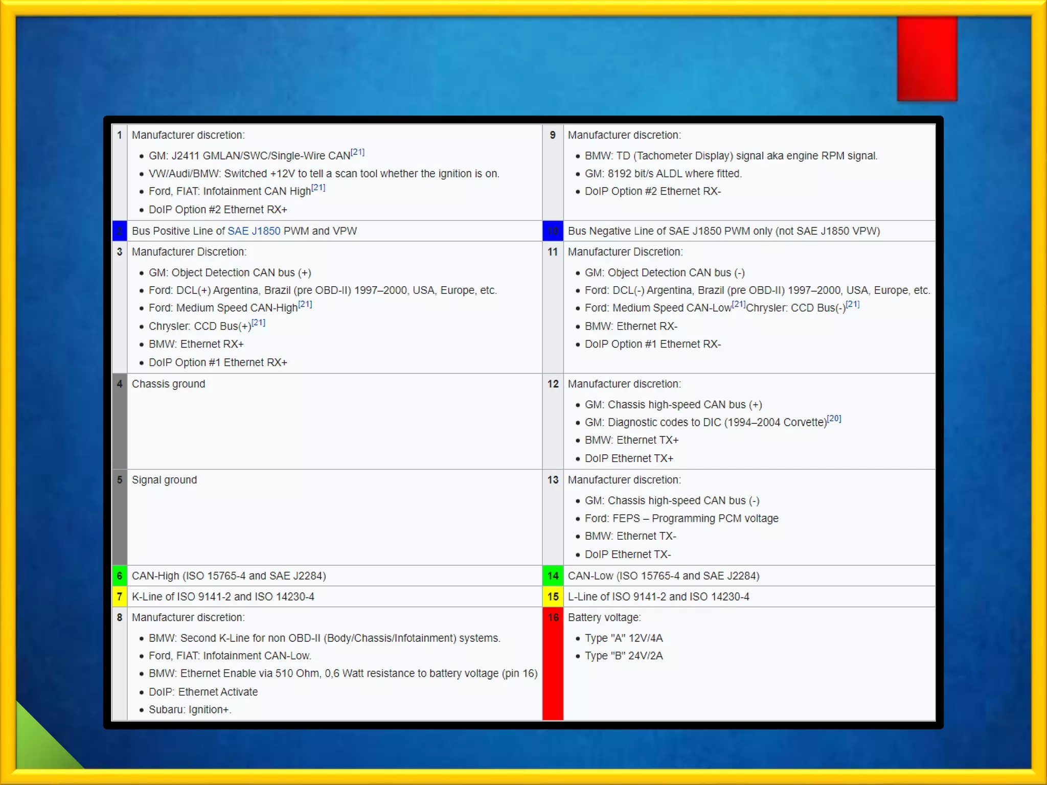
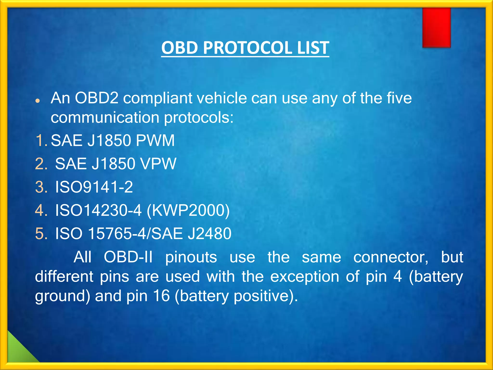
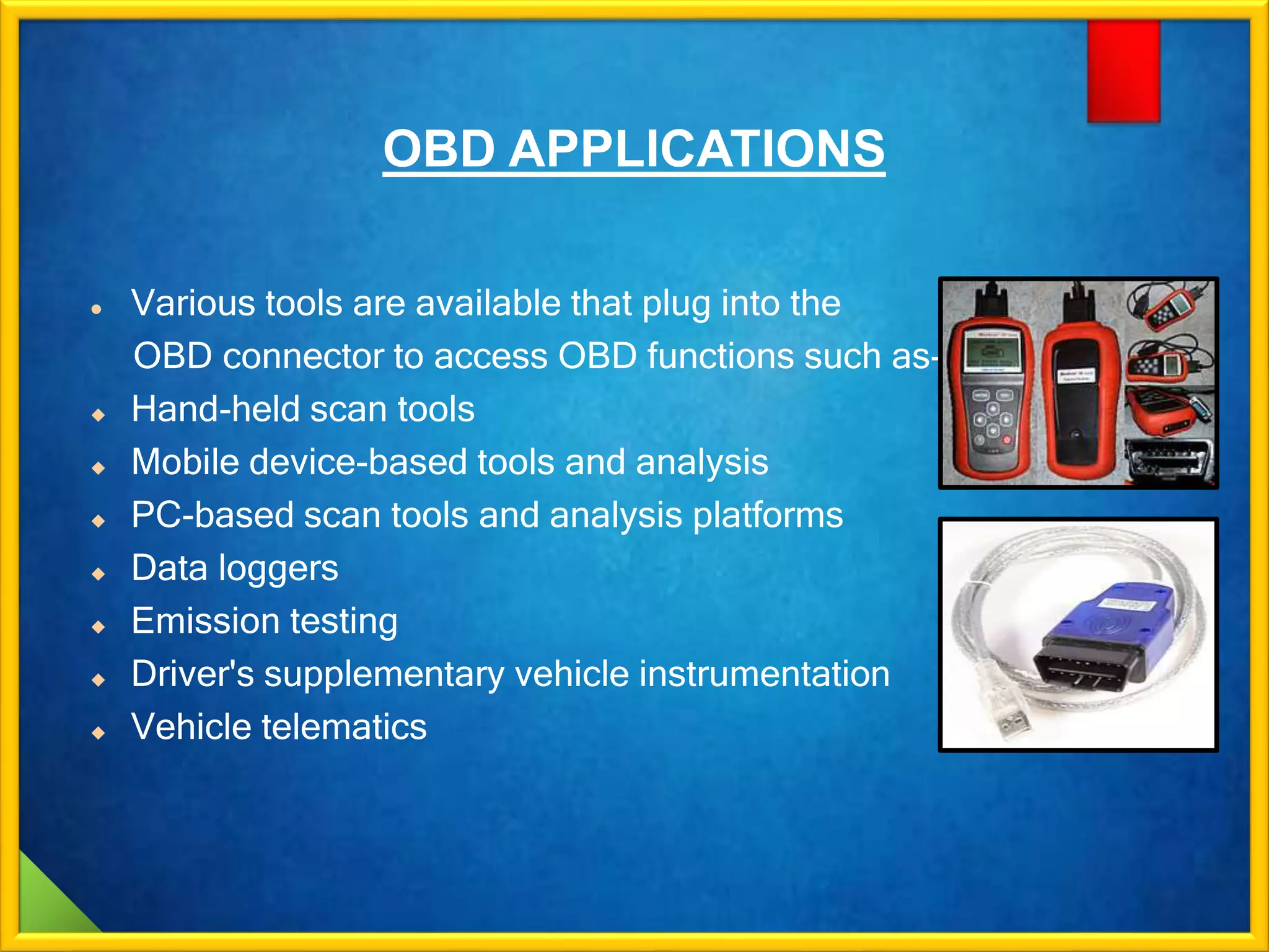
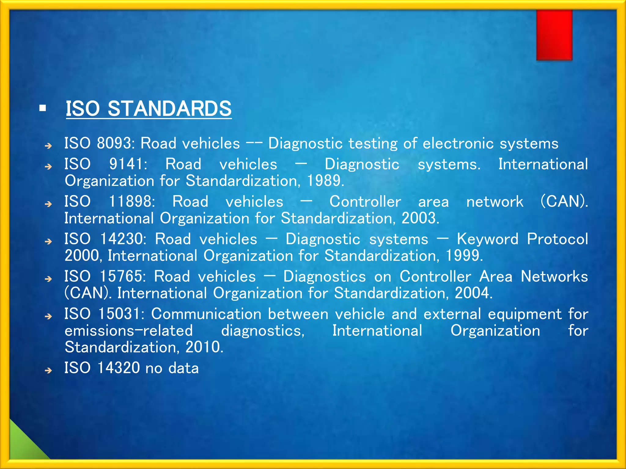
•Made by-
•Pawan Shetty (175052)
•Aditi Shinde (175053)
•Purvesh Shinde (175054)
•Yameen Siddiqui
(175055)
INTRODUCTION
Vehicles today are much more intelligent than they were years back. The
traditional vehicle timed the ignition of the spark using mechanical distributors.
This method of coordinating the timing of the spark delivery when the fuel and air
mixture were compressed in the engine cylinders wasn’t ideal.
As years went on, the ECU became more capable of supplying diagnostic and
sensor data to help mechanics identify the source of problems that arise in the
engine management system.
Eventually a standard was created that all manufacturers were encouraged
to follow. The standard became commonly known as Onboard Diagnostics (OBD).
The introduction of the standard was in an effort to encourage vehicle
manufacturers to design more reliable emission control systems. OBD-II is an
enhancement of the OBD standard that was introduced later and made mandatory.
The modern vehicle's on-board-diagnostics (OBD-II) provides a repair
technician with access to information for various vehicle sub-systems. The
amount of diagnostic information available via OBD-II has varied widely since its
introduction in the mid 1990's.
ON-BOARD DIAGNOSTICS - I
A milestone for automotive efficiency arrived in the forms of On-board
computers On Board Diagnostics, OBD, beginning in 1980. These computers would
monitor the fuel injection systems and would have simple capabilities and
adjustments, in return, were the start of something great to come. The General
Motors Company became the first to build an interface in their vehicle in 1982,
the Assembly Line Communications Link. By 1986, the ALCL, known as the ALDL,
Assembly Line Diagnostic Link, seen below in Figure Terminal Identification for On
Board Diagnostics Port, had developed into a much better system where the
problem with inconsistency in communication links had been resolved with the
implementation of The Universal Asynchronous Receiver/Transmitter.This became
known as OBD-I.
ON-BOARD DIAGNOSTICS - II
OBD-II is an improvement over OBD-I in both capability and standardization.
The OBD-II standard specifies the type of diagnostic connector and its pinout, the
electrical signalling protocols available, and the messaging format. It also provides a
candidate list of vehicle parameters to monitor along with how to encode the data for
each. There is a pin in the connector that provides power for the scan tool from the
vehicle battery, which eliminates the need to connect a scan tool to a power source
separately.
The OBD-II standard provides a list of standardized DTCs. As a result of this
standardization, a single device can query the on-board computer(s) for these
parameters in any vehicle. OBD-II standardization was prompted to simplify diagnosis
of increasingly complicated emissions equipment, and though only emission-related
codes and data are required to be transmitted through it according to U.S. Legislation.
OBD-II DIAGNOSTIC CONNECTOR
The DLC(Data Link Connector or Diagnostic Link Connector) is the
standardized 16-cavity connector where diagnostic scan tools interface with
the vehicle’s onboard computer.the DLC is usually located 12 inches from the
center of the instrument panel (dash),under or around the driver’s side for most
vehicles.
Since 1996, the data link connector (DLC) is a standardized 16 cavity
connector shown below.Connector design and location is dictated by an
industry wide standard. Vehicle manufacturers can use the empty DLC cavities
for whatever they would like.
The SAE J1962 specification provides for two standardized hardware
interfaces, called type A and type B. Both are female, 16-pin (2x8), D-shaped
connectors, and both have a groove between the two rows of pins, but type B's
groove is interrupted in the middle.
OBD PROTOCOL LIST
 An OBD2 compliant vehicle can use any of the five
communication protocols:
1.SAE J1850 PWM
2. SAE J1850 VPW
3. ISO9141-2
4. ISO14230-4 (KWP2000)
5. ISO 15765-4/SAE J2480
All OBD-II pinouts use the same connector, but
different pins are used with the exception of pin 4 (battery
ground) and pin 16 (battery positive).
OBD TROUBLE CODES
OBD-II Diagnostic Trouble Codes(DTCS) are codes that are stored
by the on-board computer diagnostic system in response to a problem
found in the vehicle.these codes identify a particular problem area and are
intended to provide you with a guide as to where a fault might be occurring
within a vehicle. OBDII Diagnostic Trouble Codes consist of a five-digit
alphanumeric code.the first character,a letter,identifies which control
system sets the code.the other four characters,all numbers,provide
additional infomation on where the DTC originated and the operating
conditions that caused it to set.
OBD APPLICATIONS
 Various tools are available that plug into the
OBD connector to access OBD functions such as-
 Hand-held scan tools
 Mobile device-based tools and analysis
 PC-based scan tools and analysis platforms
 Data loggers
 Emission testing
 Driver's supplementary vehicle instrumentation
 Vehicle telematics
STANDARDS DOCUMENTS
 SAE standards documents on OBD-I
 J1962 – Defines the physical connector used for the OBD-II interface
 J1978 – Defines minimal operating standards for OBD-II scan tools
 J1979 – Defines standards for diagnostic test modes
 J2012 – Defines standards trouble codes and definitions.
 J2178-2 – Gives data parameter definitions
 J2178-3 – Defines standards for network message frame IDs for single byte
headers
 J2178-4 – Defines standards for network messages with three byte
headers.
 SAE standards documents on HD (heavy duty) OBD
 J1939 – Defines a data protocol for heavy duty commercial vehicles
 ISO STANDARDS
 ISO 8093: Road vehicles -- Diagnostic testing of electronic systems
 ISO 9141: Road vehicles — Diagnostic systems. International
Organization for Standardization, 1989.
 ISO 11898: Road vehicles — Controller area network (CAN).
International Organization for Standardization, 2003.
 ISO 14230: Road vehicles — Diagnostic systems — Keyword Protocol
2000, International Organization for Standardization, 1999.
 ISO 15765: Road vehicles — Diagnostics on Controller Area Networks
(CAN). International Organization for Standardization, 2004.
 ISO 15031: Communication between vehicle and external equipment for
emissions-related diagnostics, International Organization for
Standardization, 2010.
 ISO 14320 no data
SECURITY ISSUES
Researchers examined the security around OBD,
And found that they were able to gain control over
many vehicle components via the interface. Further
more, they were able to upload new firmware into the
engine control units. Their conclusion is that vehicle
Embedded systems are not designed with security in mind.
The primary causes of this vulnerability lie in the tendency for vehicle
manufacturers to extend the bus for purposes other than those for which it was
designed, and the lack of authentication and authorization in the OBD specifications,
which instead rely largely on security through obscurity.
CONCLUSION
OBD-II is no longer only used by professionals to repair
vehicles. OBD-II information is commonly used by vehicle
telematics devices that perform fleet tracking, monitor fuel efficiency,
prevent unsafe driving, as well as for remote diagnostics and by pay-
as-you-drive insurance. Although originally not intended for the above
purposes, commonly supported OBD-II data such as vehicle
speed, RPM, and fuel level allow GPS-based fleet tracking devices to
monitor vehicle idling times, speeding, and over-revving. By monitoring
OBD II DTCs a company can know immediately if one of its vehicles
has an engine problem and by interpreting the code the nature of the
problem. OBD II is also monitored to block mobile phones when driving
and to record trip data for insurance purposes.
THANK YOU

OBD (On Board Diagnostics)

  • 1.
    •Made by- •Pawan Shetty(175052) •Aditi Shinde (175053) •Purvesh Shinde (175054) •Yameen Siddiqui (175055)
  • 2.
    INTRODUCTION Vehicles today aremuch more intelligent than they were years back. The traditional vehicle timed the ignition of the spark using mechanical distributors. This method of coordinating the timing of the spark delivery when the fuel and air mixture were compressed in the engine cylinders wasn’t ideal. As years went on, the ECU became more capable of supplying diagnostic and sensor data to help mechanics identify the source of problems that arise in the engine management system. Eventually a standard was created that all manufacturers were encouraged to follow. The standard became commonly known as Onboard Diagnostics (OBD). The introduction of the standard was in an effort to encourage vehicle manufacturers to design more reliable emission control systems. OBD-II is an enhancement of the OBD standard that was introduced later and made mandatory. The modern vehicle's on-board-diagnostics (OBD-II) provides a repair technician with access to information for various vehicle sub-systems. The amount of diagnostic information available via OBD-II has varied widely since its introduction in the mid 1990's.
  • 3.
    ON-BOARD DIAGNOSTICS -I A milestone for automotive efficiency arrived in the forms of On-board computers On Board Diagnostics, OBD, beginning in 1980. These computers would monitor the fuel injection systems and would have simple capabilities and adjustments, in return, were the start of something great to come. The General Motors Company became the first to build an interface in their vehicle in 1982, the Assembly Line Communications Link. By 1986, the ALCL, known as the ALDL, Assembly Line Diagnostic Link, seen below in Figure Terminal Identification for On Board Diagnostics Port, had developed into a much better system where the problem with inconsistency in communication links had been resolved with the implementation of The Universal Asynchronous Receiver/Transmitter.This became known as OBD-I.
  • 4.
    ON-BOARD DIAGNOSTICS -II OBD-II is an improvement over OBD-I in both capability and standardization. The OBD-II standard specifies the type of diagnostic connector and its pinout, the electrical signalling protocols available, and the messaging format. It also provides a candidate list of vehicle parameters to monitor along with how to encode the data for each. There is a pin in the connector that provides power for the scan tool from the vehicle battery, which eliminates the need to connect a scan tool to a power source separately. The OBD-II standard provides a list of standardized DTCs. As a result of this standardization, a single device can query the on-board computer(s) for these parameters in any vehicle. OBD-II standardization was prompted to simplify diagnosis of increasingly complicated emissions equipment, and though only emission-related codes and data are required to be transmitted through it according to U.S. Legislation.
  • 5.
    OBD-II DIAGNOSTIC CONNECTOR TheDLC(Data Link Connector or Diagnostic Link Connector) is the standardized 16-cavity connector where diagnostic scan tools interface with the vehicle’s onboard computer.the DLC is usually located 12 inches from the center of the instrument panel (dash),under or around the driver’s side for most vehicles. Since 1996, the data link connector (DLC) is a standardized 16 cavity connector shown below.Connector design and location is dictated by an industry wide standard. Vehicle manufacturers can use the empty DLC cavities for whatever they would like. The SAE J1962 specification provides for two standardized hardware interfaces, called type A and type B. Both are female, 16-pin (2x8), D-shaped connectors, and both have a groove between the two rows of pins, but type B's groove is interrupted in the middle.
  • 7.
    OBD PROTOCOL LIST An OBD2 compliant vehicle can use any of the five communication protocols: 1.SAE J1850 PWM 2. SAE J1850 VPW 3. ISO9141-2 4. ISO14230-4 (KWP2000) 5. ISO 15765-4/SAE J2480 All OBD-II pinouts use the same connector, but different pins are used with the exception of pin 4 (battery ground) and pin 16 (battery positive).
  • 8.
    OBD TROUBLE CODES OBD-IIDiagnostic Trouble Codes(DTCS) are codes that are stored by the on-board computer diagnostic system in response to a problem found in the vehicle.these codes identify a particular problem area and are intended to provide you with a guide as to where a fault might be occurring within a vehicle. OBDII Diagnostic Trouble Codes consist of a five-digit alphanumeric code.the first character,a letter,identifies which control system sets the code.the other four characters,all numbers,provide additional infomation on where the DTC originated and the operating conditions that caused it to set.
  • 9.
    OBD APPLICATIONS  Varioustools are available that plug into the OBD connector to access OBD functions such as-  Hand-held scan tools  Mobile device-based tools and analysis  PC-based scan tools and analysis platforms  Data loggers  Emission testing  Driver's supplementary vehicle instrumentation  Vehicle telematics
  • 10.
    STANDARDS DOCUMENTS  SAEstandards documents on OBD-I  J1962 – Defines the physical connector used for the OBD-II interface  J1978 – Defines minimal operating standards for OBD-II scan tools  J1979 – Defines standards for diagnostic test modes  J2012 – Defines standards trouble codes and definitions.  J2178-2 – Gives data parameter definitions  J2178-3 – Defines standards for network message frame IDs for single byte headers  J2178-4 – Defines standards for network messages with three byte headers.  SAE standards documents on HD (heavy duty) OBD  J1939 – Defines a data protocol for heavy duty commercial vehicles
  • 11.
     ISO STANDARDS ISO 8093: Road vehicles -- Diagnostic testing of electronic systems  ISO 9141: Road vehicles — Diagnostic systems. International Organization for Standardization, 1989.  ISO 11898: Road vehicles — Controller area network (CAN). International Organization for Standardization, 2003.  ISO 14230: Road vehicles — Diagnostic systems — Keyword Protocol 2000, International Organization for Standardization, 1999.  ISO 15765: Road vehicles — Diagnostics on Controller Area Networks (CAN). International Organization for Standardization, 2004.  ISO 15031: Communication between vehicle and external equipment for emissions-related diagnostics, International Organization for Standardization, 2010.  ISO 14320 no data
  • 12.
    SECURITY ISSUES Researchers examinedthe security around OBD, And found that they were able to gain control over many vehicle components via the interface. Further more, they were able to upload new firmware into the engine control units. Their conclusion is that vehicle Embedded systems are not designed with security in mind. The primary causes of this vulnerability lie in the tendency for vehicle manufacturers to extend the bus for purposes other than those for which it was designed, and the lack of authentication and authorization in the OBD specifications, which instead rely largely on security through obscurity.
  • 13.
    CONCLUSION OBD-II is nolonger only used by professionals to repair vehicles. OBD-II information is commonly used by vehicle telematics devices that perform fleet tracking, monitor fuel efficiency, prevent unsafe driving, as well as for remote diagnostics and by pay- as-you-drive insurance. Although originally not intended for the above purposes, commonly supported OBD-II data such as vehicle speed, RPM, and fuel level allow GPS-based fleet tracking devices to monitor vehicle idling times, speeding, and over-revving. By monitoring OBD II DTCs a company can know immediately if one of its vehicles has an engine problem and by interpreting the code the nature of the problem. OBD II is also monitored to block mobile phones when driving and to record trip data for insurance purposes.
  • 14.