This document discusses removing sulfur from petroleum refining using a Distributed Control System (DCS). It begins with an introduction to hydrodesulfurization, the catalytic process used to remove sulfur from fuels to reduce emissions. The objective is to automate the sulfur removal process using a DCS. It describes the sulfur removal process and hydrogen sulfide capture. It then provides an overview of DCS and its advantages over centralized control systems. The document details implementing control logic like temperature, pressure, and flow controls into the DCS. It discusses results like improved continuity and flexibility compared to a PLC system. In conclusion, the DCS provides improved plant control, efficiency, and crude oil quality for the desulfurization process.
![IOSR Journal of Engineering (IOSRJEN) www.iosrjen.org
ISSN (e): 2250-3021, ISSN (p): 2278-8719
Vol. 04, Issue 05 (May. 2014), ||V5|| PP 19-22
International organization of Scientific Research 19 | P a g e
Removal of Sulfur in Petroleum Refining Using DCS
S.Ramraj1
C.Anandaraj2
1
Assistant Professor & Head, Dept. of EIE,
2
Assistant Professor, Dept. of EEE,
Thiruvalluvar College of Engineering and Technology,Vandavasi.
Abstract: - Petroleum refining area Sulfur is naturally present as an impurity in fossil fuels. When the fuels are
burned, the sulfur is Released as sulfur dioxide—an air pollutant responsible for respiratory problems and acid
rain. Environmental regulations have increasingly restricted sulfur dioxide emissions, forcing fuel Processors to
remove the sulfur from both fuels and exhaust gases. The cost of removing sulfur from natural gas and
petroleum is high. In natural gas, sulfur is present mainly as hydrogen sulfide gas (H2S), while in crude oil it is
present in sulfur-containing organic compounds which are converted into hydrocarbons and H2S during the
removal process (hydro desulfurization). This well-established process uses partial combustion and catalytic
oxidation to convert about 97% of the H2S to elemental sulfur. Implement Distributed Control System (DCS)
CENTUM CS3000 to automate the removal process in petroleum refining.
Keywords: - DCS, Valve, Parameters, Automation
I. INTRODUCTION
Hydrodesulfurization(HDS) is a catalytic chemical process widely used to remove sulfur (S)
from natural gas and from refined petroleum products such as gasoline or petrol, jet fuel, kerosene, diesel,
and fuel oils. The purpose of removing the sulfur is to reduce the sulfur dioxide (SO2) emissions that result from
using those fuels in automotive vehicles, aircraft, locomotives, ships, gas or oil burning power plants, residential
and industrial furnaces, and other forms of fuel combustion. Another important reason for removing sulfur from
the naphtha streams within a petroleum refinery is that sulfur, even in extremely low
concentrations, poisons the noble metal catalysts (platinum and rhenium) in the catalytic reforming units that are
subsequently used to upgrade the octane rating of the naphtha streams[3]. The industrial hydrodesulfurization
processes include facilities for the capture and removal of the resulting hydrogen sulfide (H2S) gas. In petroleum
refineries, the hydrogen sulfide gas is then subsequently converted into by product elemental sulfur or sulfuric
acid (H2SO4).
II. OBJECTIVE
The main objective of the project is to Design and Develop a Removal of sulfur in petroleum refining
using DCS Integration. Programming the system in DCS using function block diagram. To remove the sulfur in
natural gas, diesel, petrol, for emission control process. The industrial hydrodesulfurization processes include
facilities forthe capture and removal of the resulting hydrogen sulfide (H2S) gas. Finally the hydrogen sulfide
gas is then subsequently converted into by product elemental sulfur or sulfuric acid (H2SO4).Yokogawa has
developed software for DCS control system named it as CENTUM CS3000[1]. DCS can handle vast amount of
process data and can be configured without major changes in software and hardware architecture.
III. PROCESS DESCRIPTION
Hydrodesulfurization (HDS) is a catalytic chemical process widely used to remove sulfur (S)
from natural gas and from refined petroleum products such as gasoline or petrol, jet fuel, kerosene, diesel,
and fuel oils. The purpose of removing the sulfur is to reduce the sulfur dioxide (SO2) emissions that result from
using those fuels in automotive vehicles, aircraft, railroad locomotives, ships, gas or oil burning power plants,
residential and industrial furnaces, and other forms of fuel combustion. Another important reason for removing
sulfur from the naphtha streams within a petroleum refinery is that sulfur, even in extremely low
concentrations, poisons the noble metal catalysts (platinum and rhenium) in the catalytic reforming units that are
subsequently used to upgrade the octane rating of the naphtha streams.
The industrial hydrodesulfurization processes include facilities for the capture and removal of the
resulting hydrogen sulfide (H2S) gas. In petroleum refineries, the hydrogen sulfide gas is then subsequently
converted into by product elemental sulfur or sulfuric acid (H2SO4). In fact, the vast majority of the 64,000,000
metric tons of sulfur produced worldwide in 2005 was by-product sulfur from refineries and other hydrocarbon
processing plants. An HDS unit in the petroleum refining industry is also often referred to as a hydrotreater](https://image.slidesharecdn.com/d04551922-140612065149-phpapp02/75/D04551922-1-2048.jpg)
![Removal of Sulfur in Petroleum Refining Using DCS
International organization of Scientific Research 20 | P a g e
A. BLOCK DIAGRAM
The image below is a schematic depiction of the equipment and the process flow streams in a typical refinery
HDS unit.
Figure 1: Typical Hydrodesulfurization Unit
IV. OVERVIEW OF DCS
DCS is one of the most important control systems in the recent years, it is suitable for process control
as well as in general business application environment. Digital control system uses microprocessors to do the
control functions like feedback, feed forward and sequential controls. Digital control systems are preferred over
analog control systems since it is easy to interface with computers for data analysis. There are two types of
control systems;
(a) Centralized Control System
(b) Distributed Control System
I. Centralized Control System:
This station is connected to a man machine interface for the purpose of monitoring. FCS accepts a set
of multiple inputs from the field known as the process variables (PV1, PV2 etc). These variables were evaluated
using another set of variables known as the set point variables (SV1, SV2 etc). The corresponding outputs
generated are known as manipulated variables (MV1, MV2 etc.,). The function of the man-machine interface is
to monitor the process and also to provide the adequate set points meant for control. Drawbacks of centralized
control system are; a) if the CPU fails the entire plants gets affected. b) Redundancy concept is not available.
II. Distributed Control System:
A Distributed Control System may be defined as a system of Digital Instrumentation that is distributed
geographically and functionally. Geographical distribution comes from the fact that the electronic assemblies
are located in processing areas and they are wired to the control room. Functional distribution in a DCS implies
that the same system can control different plants of an industry in a time sharing basis. Advantages of
Distributed Control System are: a) control function is distributed among multiple CPUs ( Field Control
Stations).Hence failure of one FCS does not affect the entire plant. b) Redundancy is available at various levels.
V. IMPLEMENTATION OF DCS IN FIELD INSTRUMENTS
This chapter presented with the DCS functions according to the required program of action and
implementing the same into Field Instruments. Before implementing the DCS, first step is to analyze the Piping
and Instrument Diagram (P&ID) of all the 4 stations and identify the control loops for which the control logic is
developed. The various functional blocks of CENTUM CS3000 software are explained briefly which are used in
programming the control logic [1]. A. Functional blocks used to implement DCS There are many types of
functional blocks in DCS software, in which some of them are useful in developing control logic are explained
here below
1) Controller block (PID):
It combines the three types of actions, Proportional- Integral-Derivative. This is the most widely used control
block for closed loop system. The control based on the deviation of the process variable from set value.](https://image.slidesharecdn.com/d04551922-140612065149-phpapp02/75/D04551922-2-2048.jpg)
![Removal of Sulfur in Petroleum Refining Using DCS
International organization of Scientific Research 22 | P a g e
alarm message will be displayed with buzzer that INDC51 is voted out. If all are within range of error and alarm
message will be displayed as reliable. If all are in discrepancy then the controller will shift to manual mode.
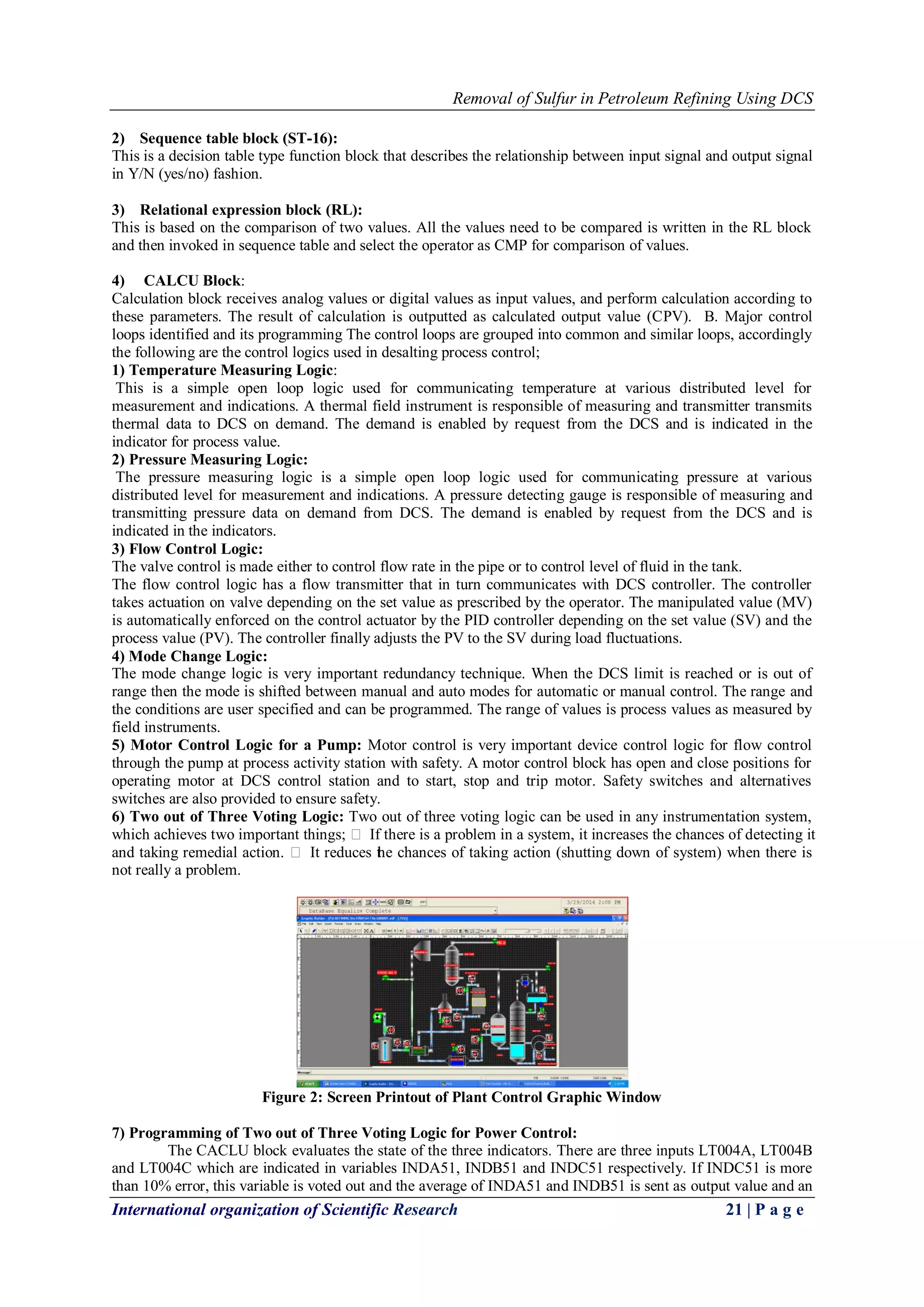
The process Control Graphic Window (CGW) is important in Human Interface System (HIS), which allows
operator to monitor and navigate through various process parameters in real time and take necessary decision
and action according to the situations in the process control. The graphic window is a simulator window, which
will simulate the exact working in field and reflect the process values, alarms and message to the master control
and the operator in the field. A particular situation is indicated by announciator messages and operator message
with alarms. Desalting Plant control graphic window that will monitor the entire plant is shown in Figure
8) Here ON and OFF are the control switches for plant control. The CGW shows the process in pictures and
indications with tag names.
VI. RESULT AND DISCUSSION
The problems faced with PLC and how it was able to overcome by implementing DCS are explained here
below;
1) Continuity of Process:
In case of motor control block, PLC does not provide any redundant system when sudden break down of motor
control hence PLC will not assure continues process. DCS is well known for its redundancy technique, it
provides another motor control with bypass in case of any shut down of first motor control.
2) Control Logic Execution time:
Since PLC has ladder logic programming for all the control loops, whose execution takes more time as the
program flows line by line. DCS is flexible, easy in programming and execution time is less when compared to
PLC.
3) Flexibility:
Once the entire setup is ready using PLC one cannot change it, if any change is required then the entire setup
has to be replaced and it is very costly, whereas DCS has standard algorithms in the form of blocks which are
ready to use and debug easily.
4) Data Handling Capacity:
PLC control system becomes complex in terms of software and hardware configuration as the process becomes
complicated, whereas DCS can handle vast amount of process data and can be configured without major
changes in software and hardware architecture.
5) Programming & Monitoring:
PLC control system will helps only in developing the programming part for control loops and for monitoring
purpose it uses separate software called SCADA. But in the case of DCS control system, the programming and
monitoring is done in the same software.
VII. CONCLUSION
Following conclusions are made from the research work on adopting DCS to the desalting process; The
DCS system gives a clear view of performance of the plant and its control which is enhanced due to the
concept of decentralization and redundancy.
The real time execution of control is communicated between DCS and field station is done through various
field control instruments.
The DCS system is ensured with safety such that even any one of the stations is failed, the other stations in
the field will be working without interruption.
After implementing the DCS system, overall efficiency of the plant control and quality of the crude oil has
improved.
The desalting process controlled using DCS enables to manage the process as a complete system, with
control over the various sub systems.
REFERENCE
[1] CS 3000 Engineering Manual, Yokogawa Electric Corporation, Japan.
[2] Gary, J.H. and Handwerk, G.E. (1984). Petroleum Refining Technology and Economics (2nd Ed.). Marcel
Dekker, Inc. ISBN 0-8247-7150-8.
[3] Hydrodesulfurization Technologies and Costs Nancy Yamaguchi, Trans Energy Associates, William and
Flora Hewlett Foundation Sulfur Workshop, Mexico City, May 29–30, 2003
[4] Diesel Sulfur published online by the National Petrochemical & Refiners Association (NPRA)
[5] Topsøe, H.; Clausen, B. S.; Massoth, F. E., Hydrotreating Catalysis, Science and Technology, Springer-
Verlag: Berlin, 1996.](https://image.slidesharecdn.com/d04551922-140612065149-phpapp02/75/D04551922-4-2048.jpg)


![Vibe Coding vs. Spec-Driven Development [Free Meetup]](https://cdn.slidesharecdn.com/ss_thumbnails/vibecodingvsspecdrivendevelopment-251209105622-43f455e7-thumbnail.jpg?width=640&height=640&fit=bounds)


