Downloaded 139 times

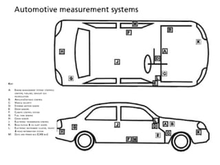

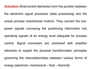

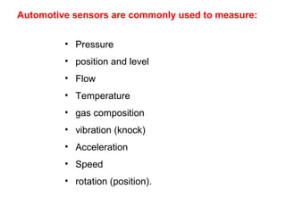
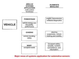


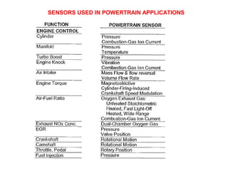
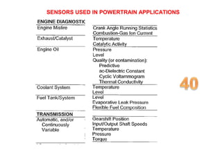
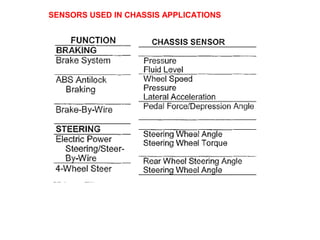
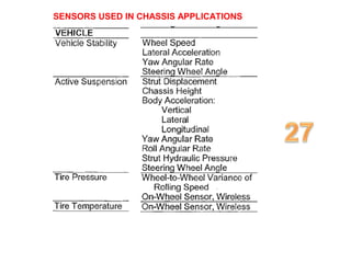

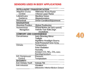
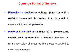
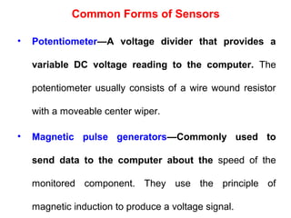
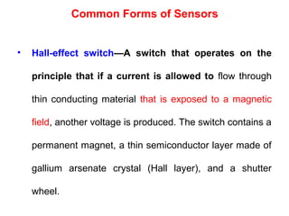


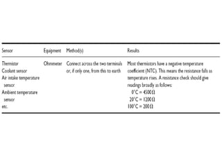
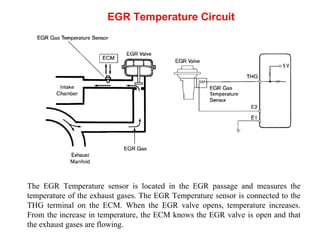
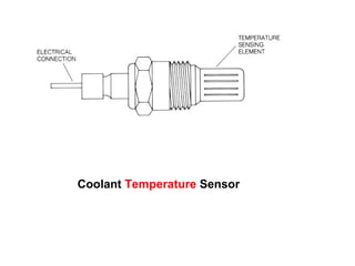
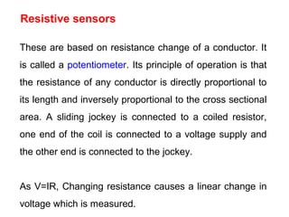
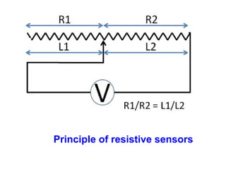
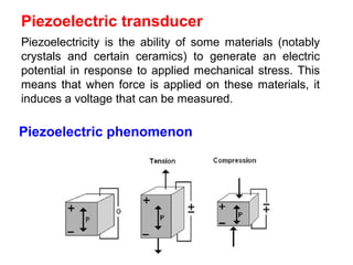
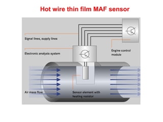
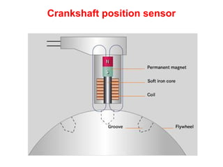
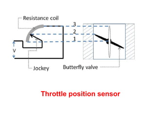
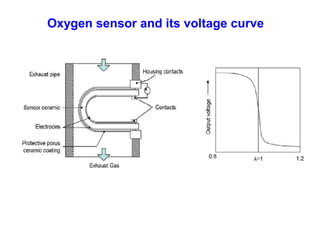

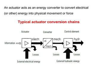
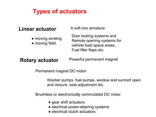
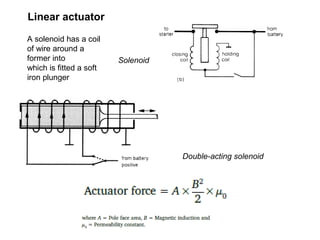
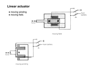


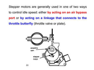


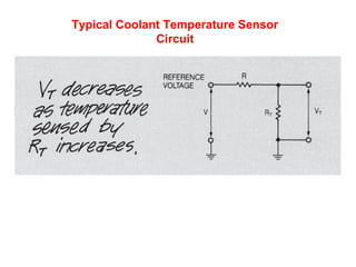

The document discusses various automotive sensors and actuators. It provides details on Hall effect, thermistor, piezoelectric and other common sensor types used in vehicles. It describes sensors for measuring oxygen concentration, air flow, manifold pressure, throttle position, oil pressure, vehicle speed and more. Actuators discussed include stepper motors, relays, and how solenoids are used for fuel injectors and EGR valves to regulate gas flow. The principles and applications of different sensor technologies like resistive, optical, and piezoelectric sensors are also summarized.


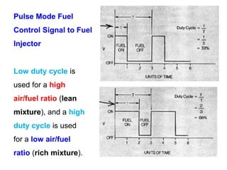
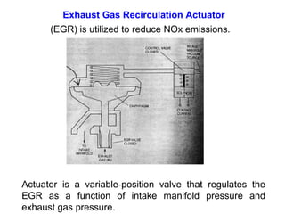
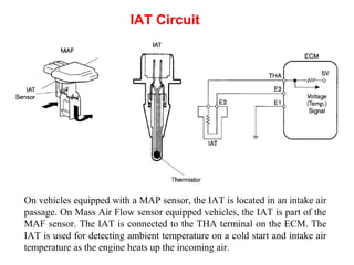
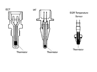
![Electronic fuel injection system [EFI]](https://cdn.slidesharecdn.com/ss_thumbnails/efibilkulfinal-171227111232-thumbnail.jpg?width=640&height=640&fit=bounds)


