Downloaded 302 times
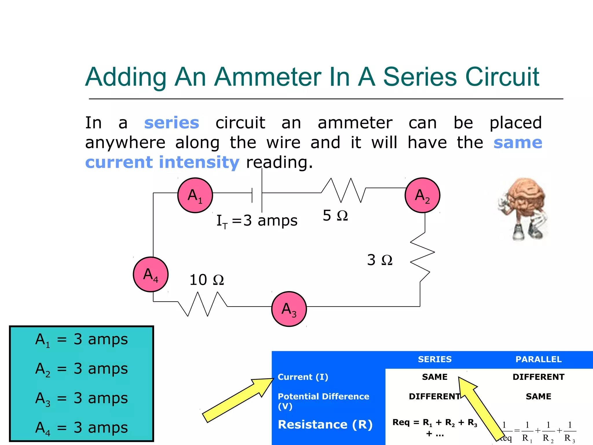
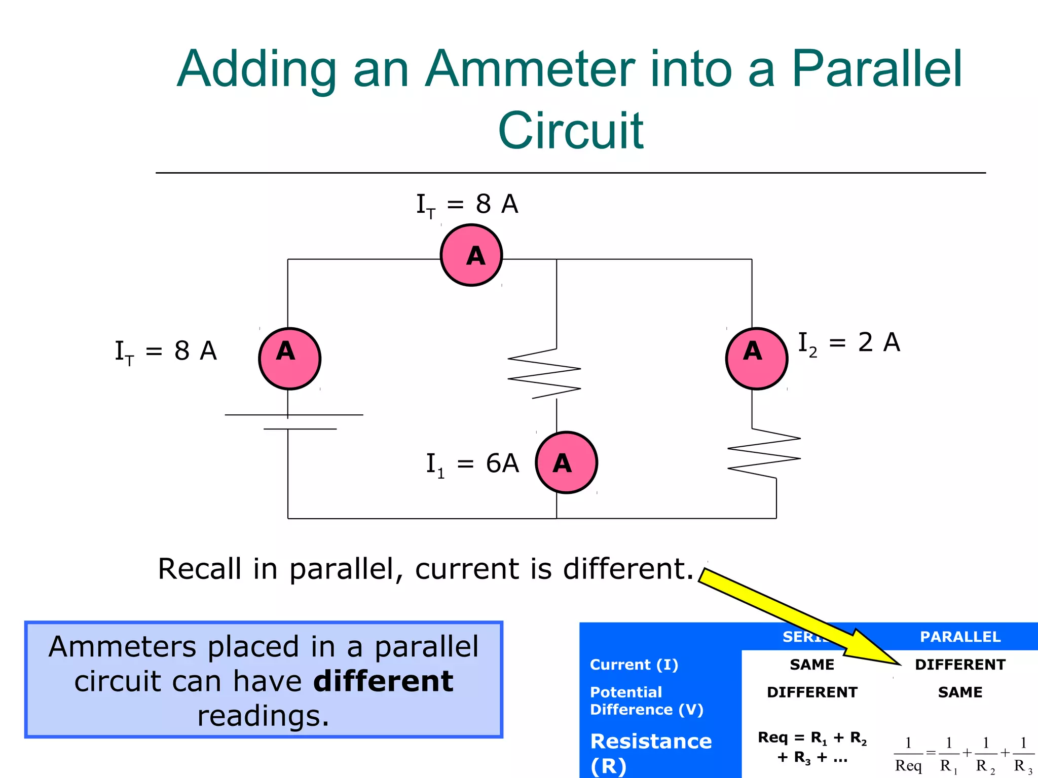
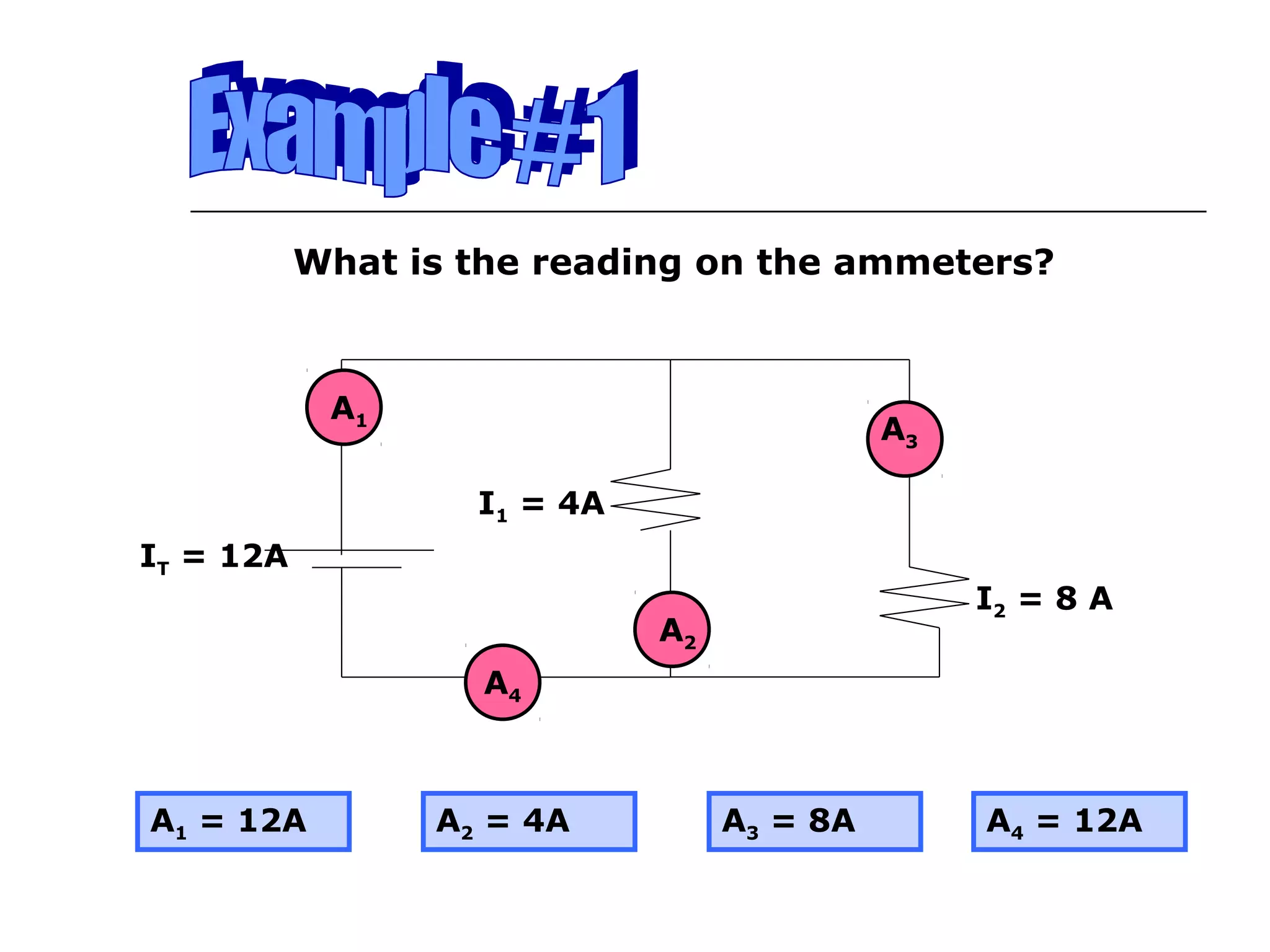
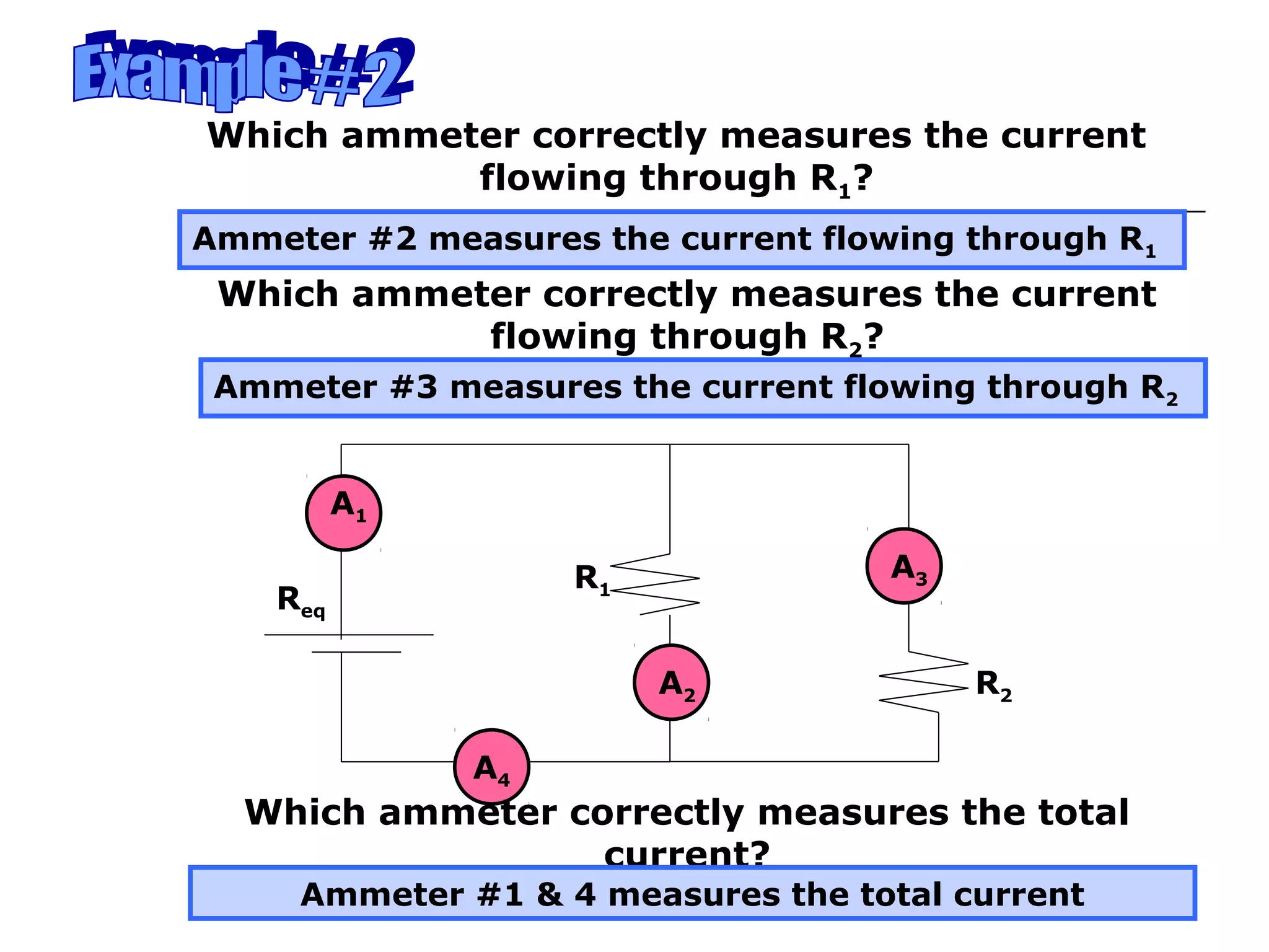
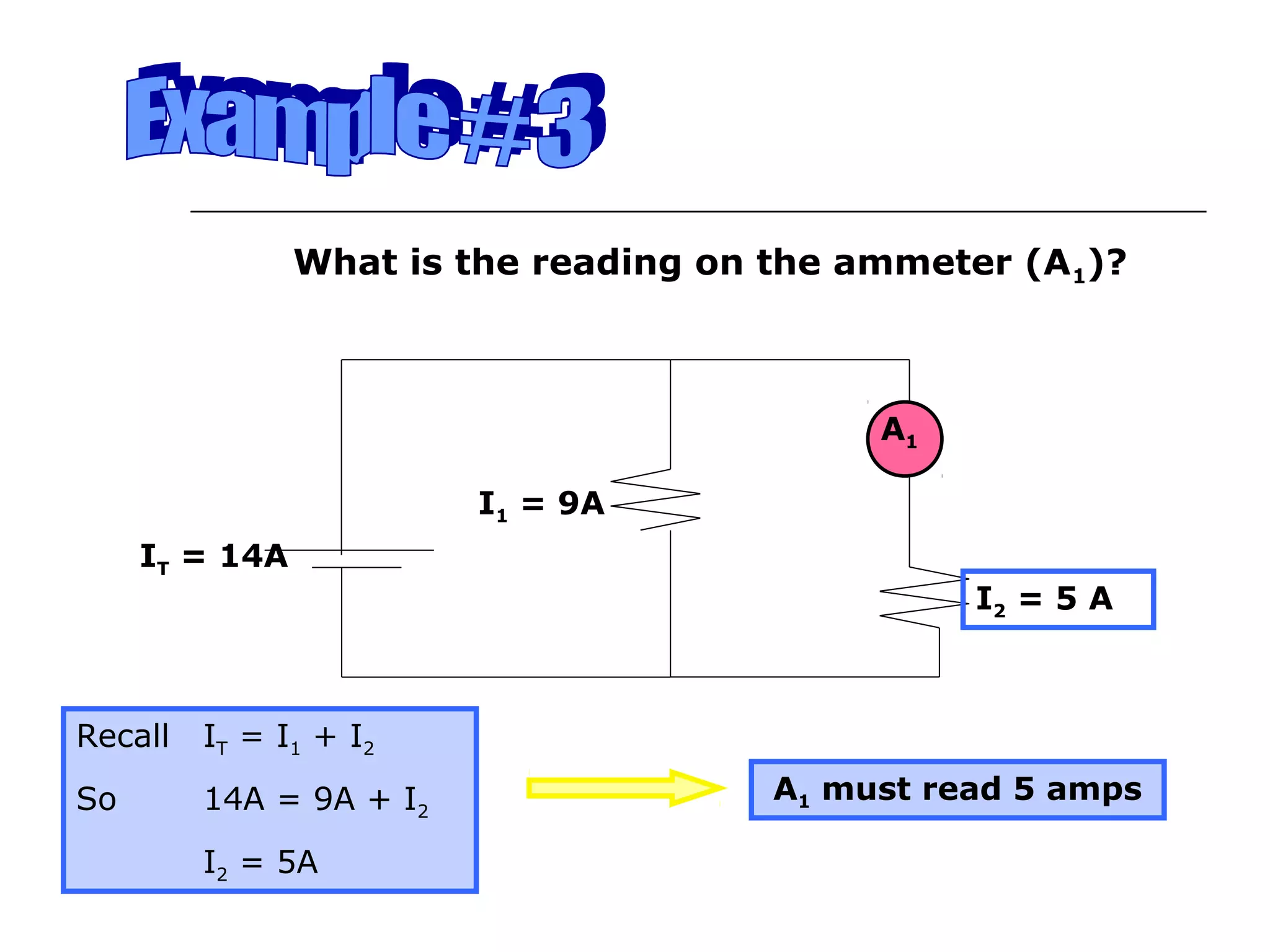
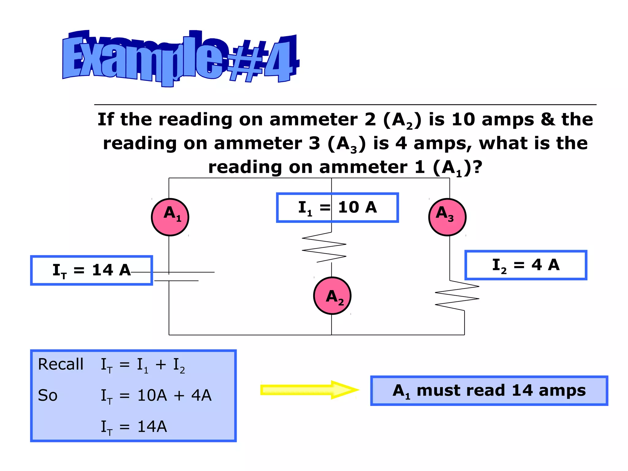
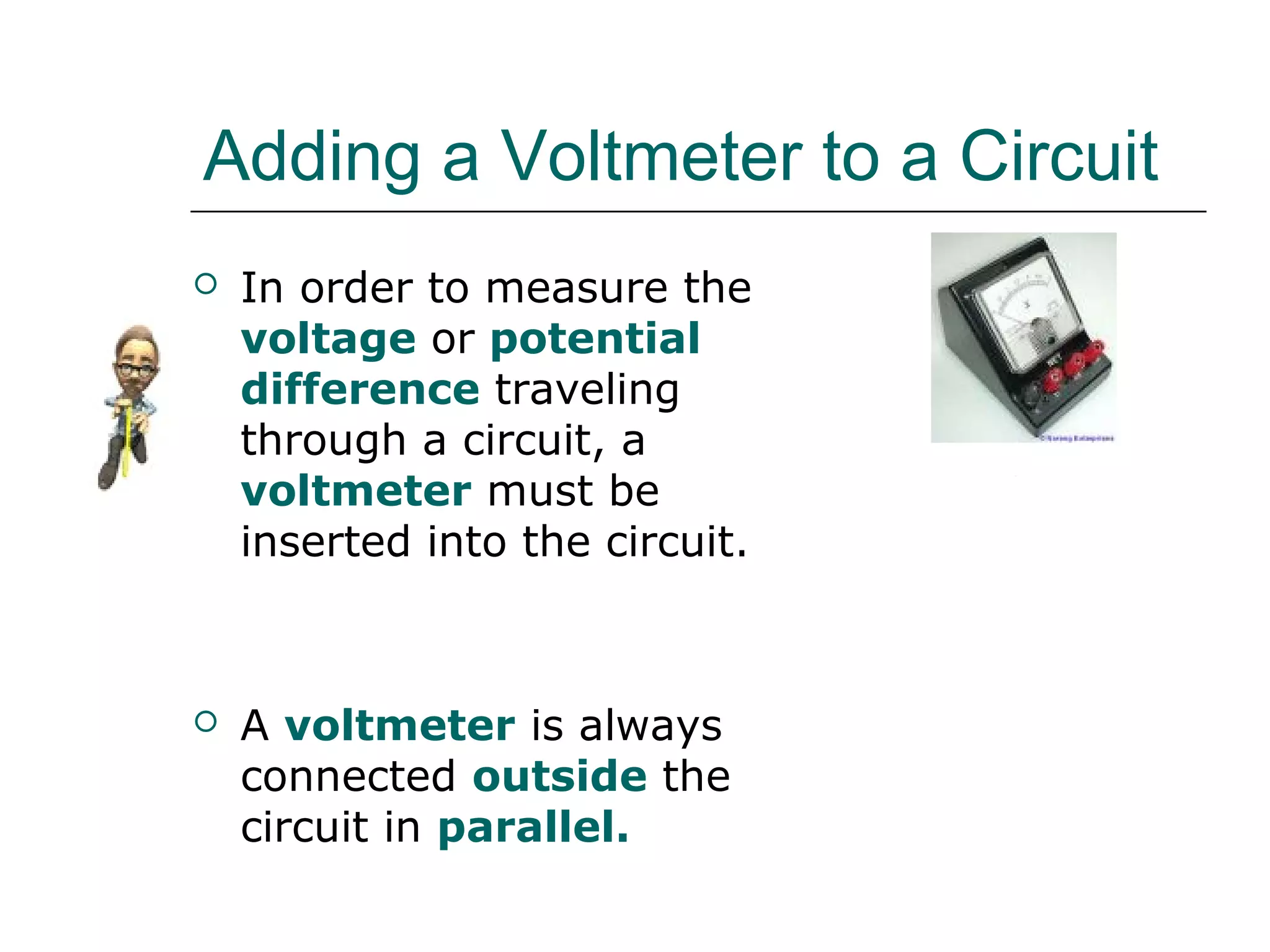
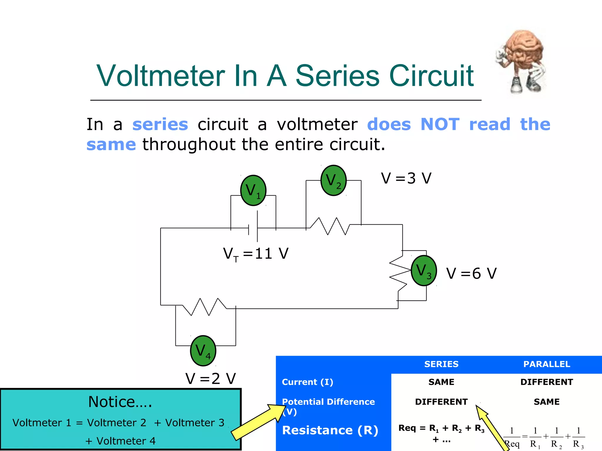
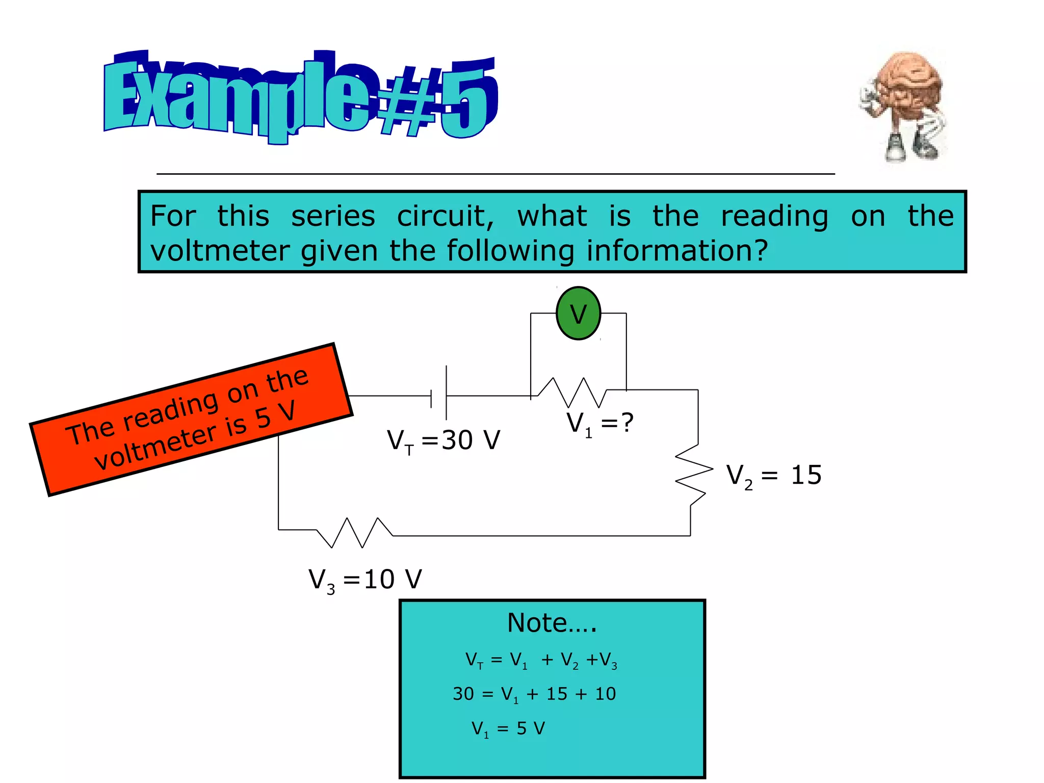
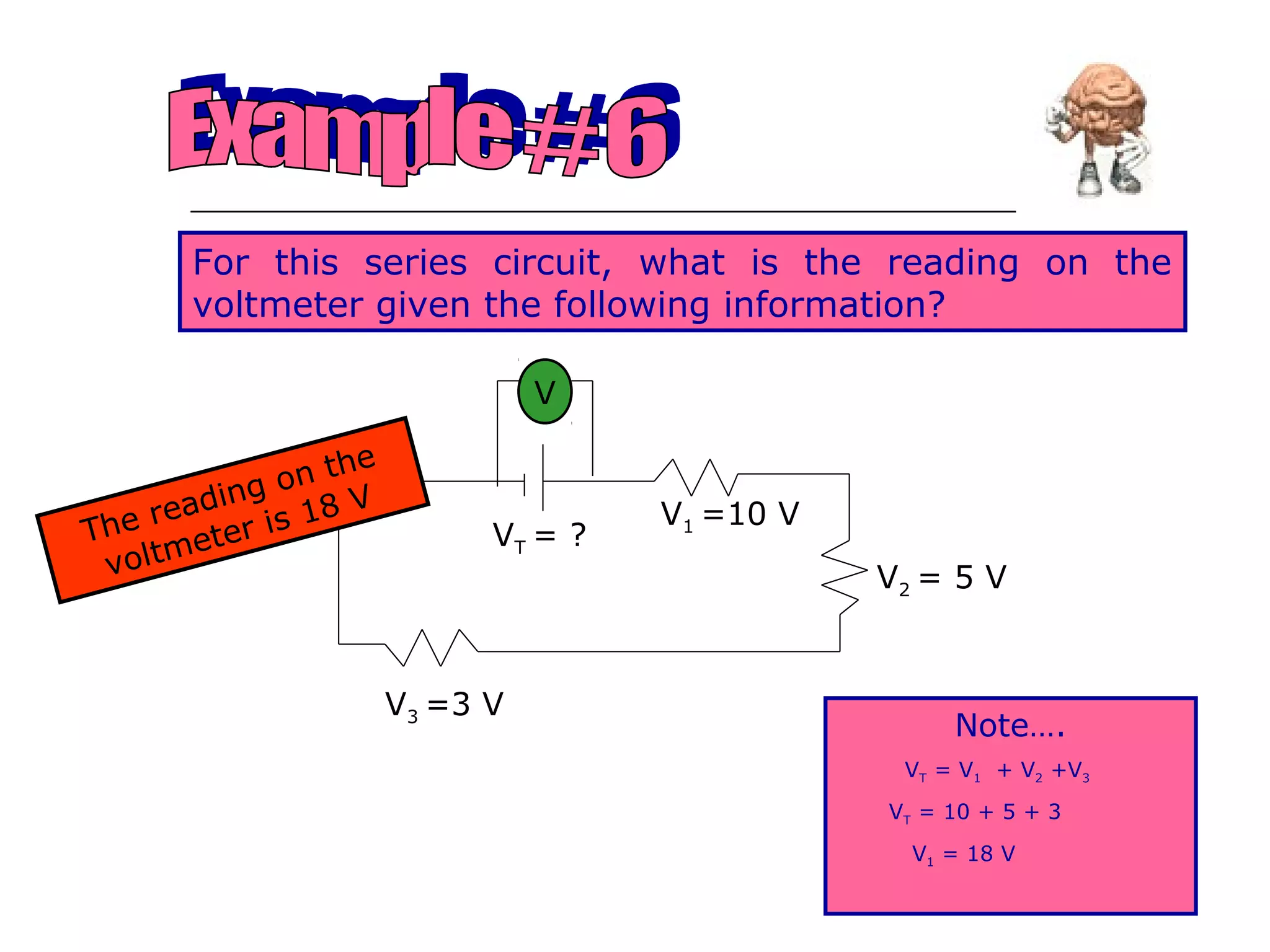
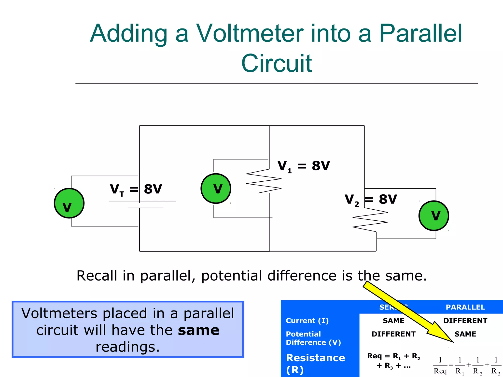
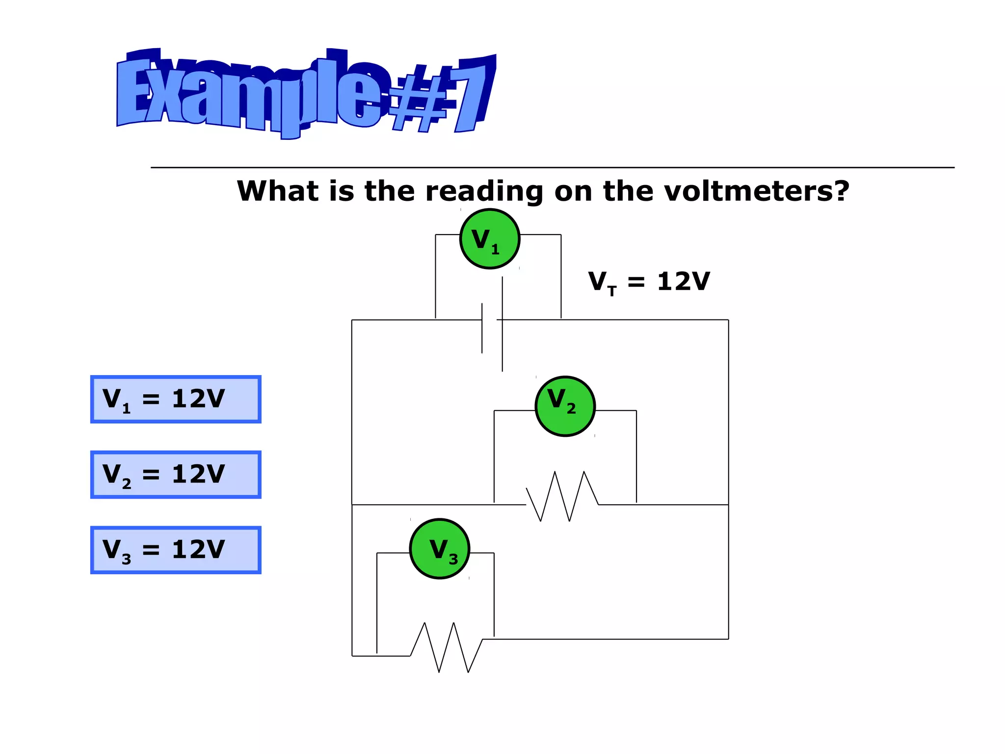
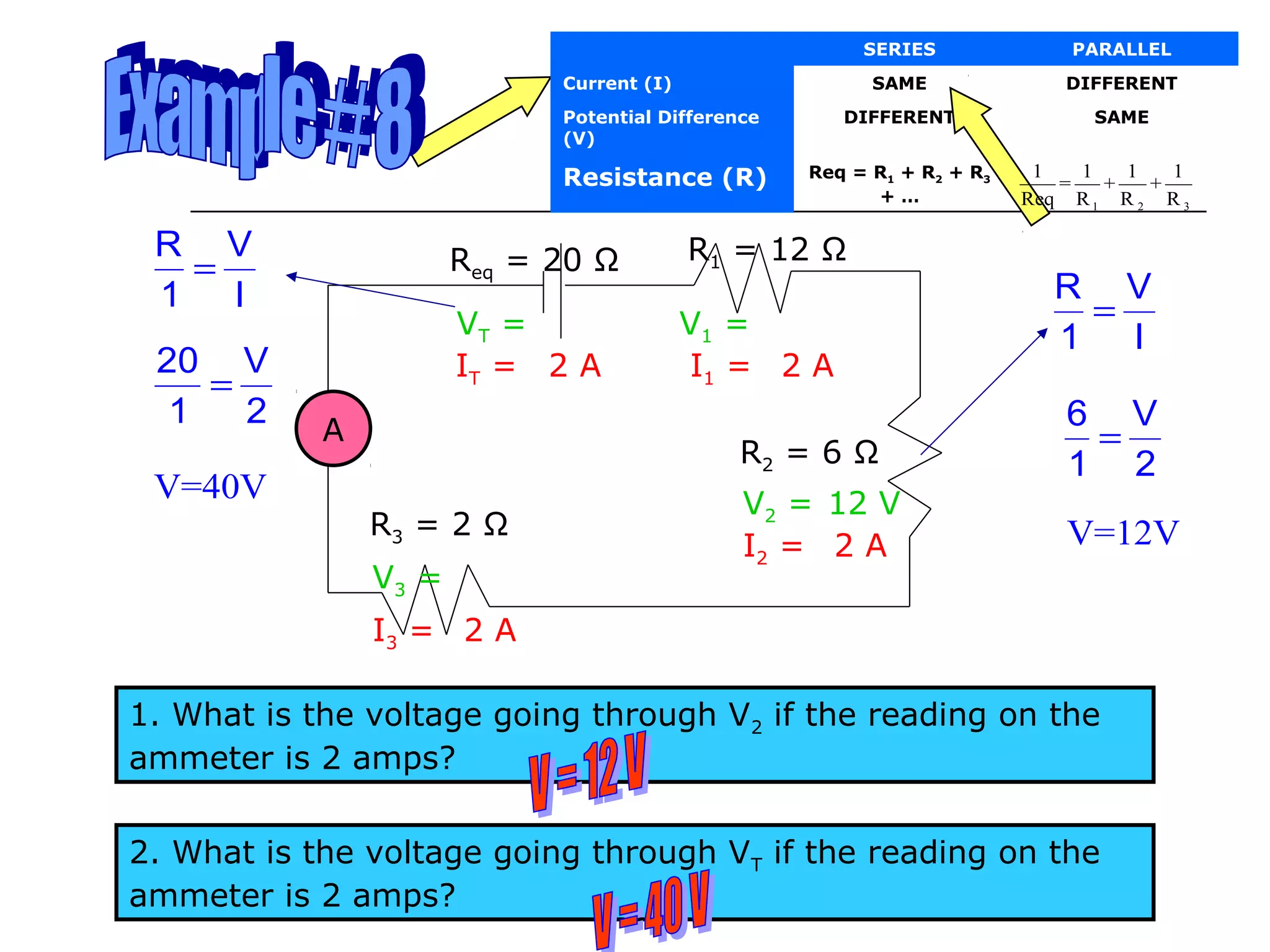
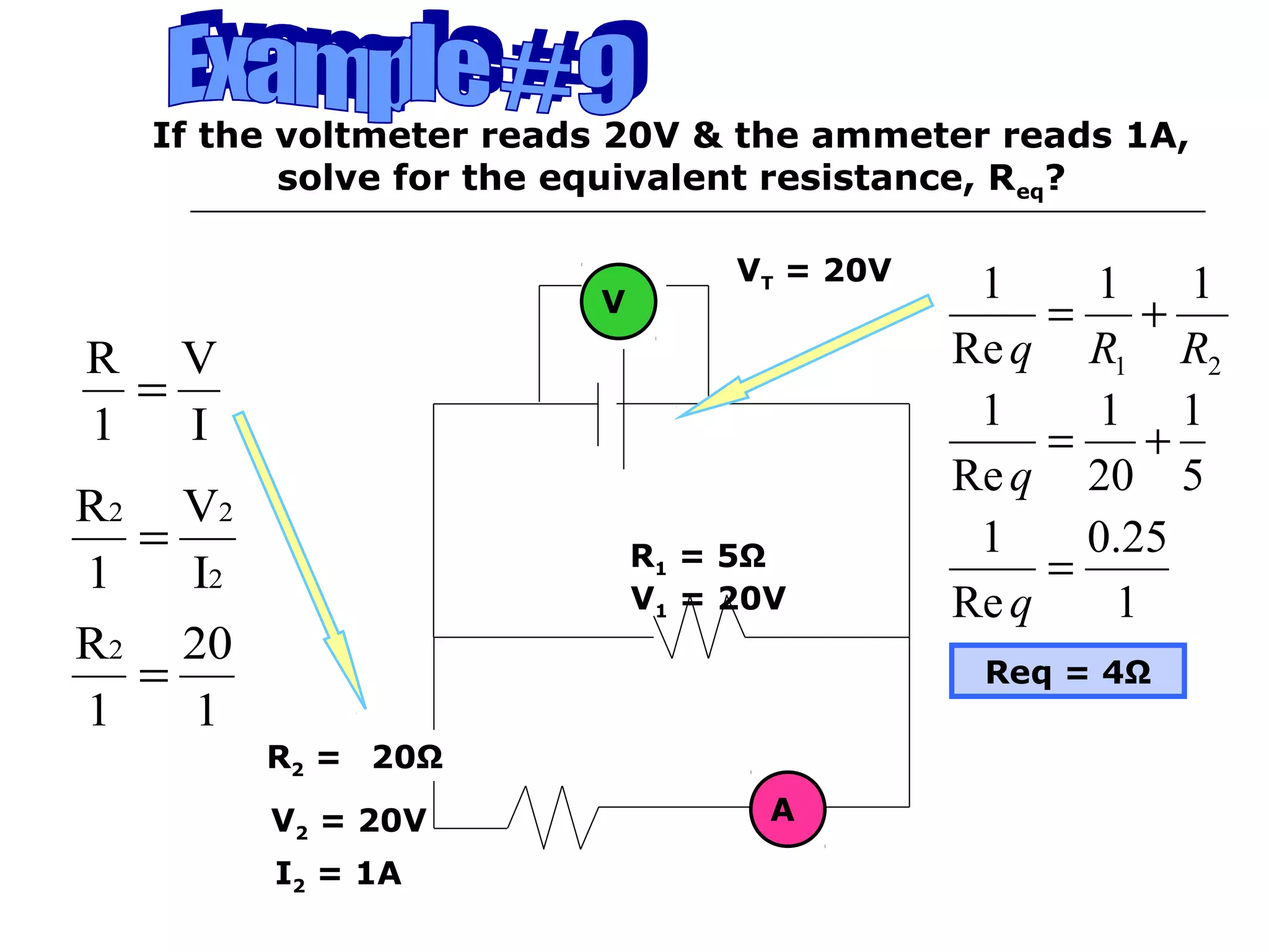
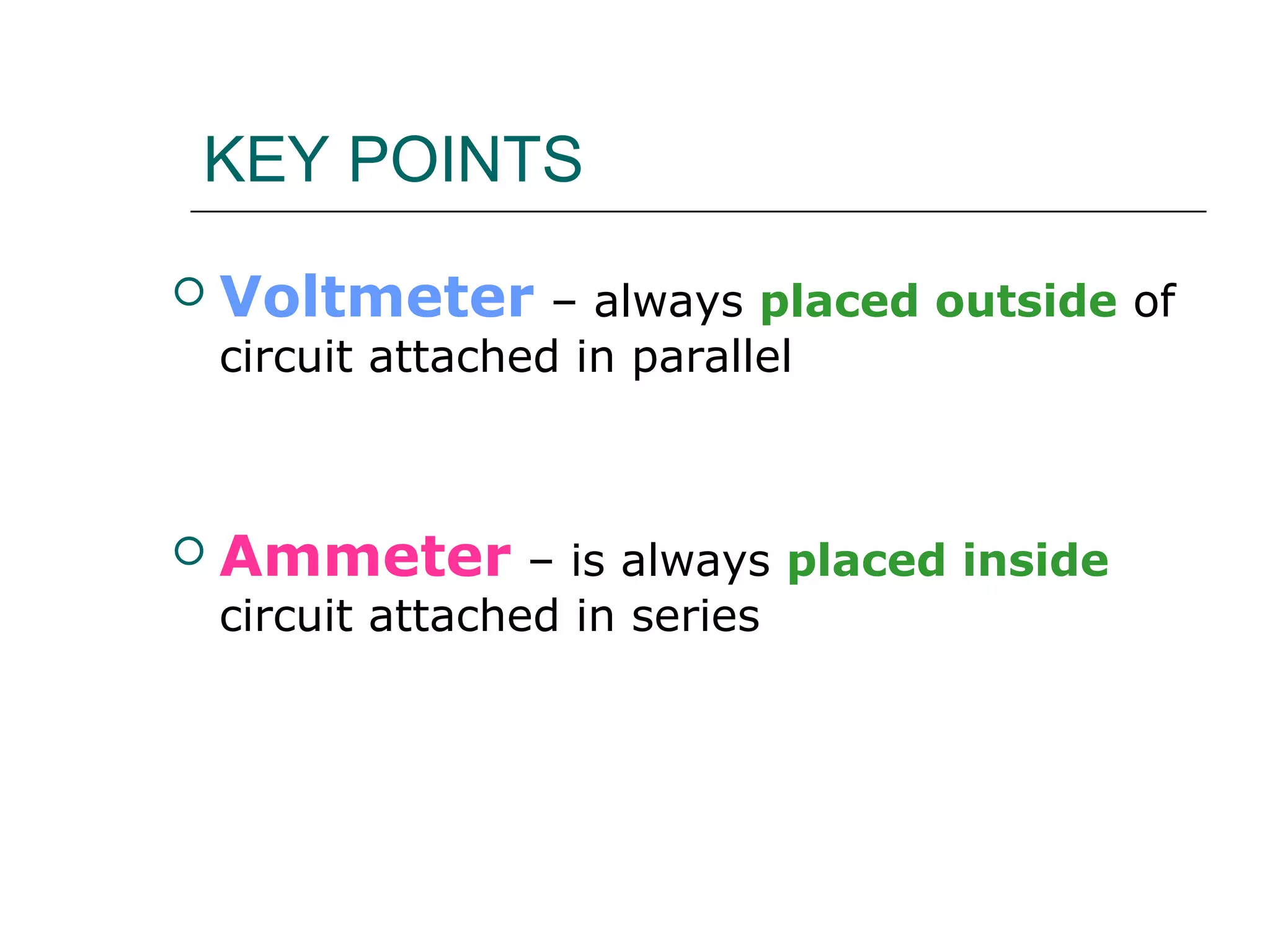


This document discusses ammeters and voltmeters and how they are used in electric circuits. It explains that ammeters must be connected in series to measure current, while voltmeters are connected in parallel to measure potential difference. Examples are given of correctly and incorrectly connecting these instruments in series and parallel circuits. Key points are that in series circuits, current is the same but potential difference varies, while in parallel circuits the potential difference is the same but current can vary. Practice problems are provided to help understand how to use ammeters and voltmeters to solve circuit problems.


![Circuits 1[1]](https://cdn.slidesharecdn.com/ss_thumbnails/circuits11-110206102031-phpapp02-thumbnail.jpg?width=640&height=640&fit=bounds)