1) This document discusses basic electric circuits including potential difference, voltage, current, resistance, Ohm's law, and different circuit configurations like series, parallel and compound circuits.
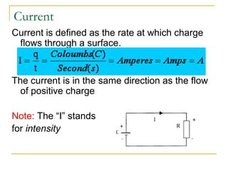
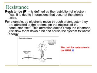
2) Key principles include that electric potential difference drives current flow, circuits require a closed path and energy source, and Ohm's law defines the relationship between voltage, current and resistance.
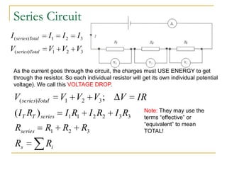
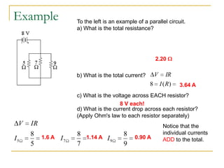
3) Circuit analysis involves applying concepts like voltage division in series circuits and current division in parallel circuits to calculate values like total resistance, current and voltage drops.