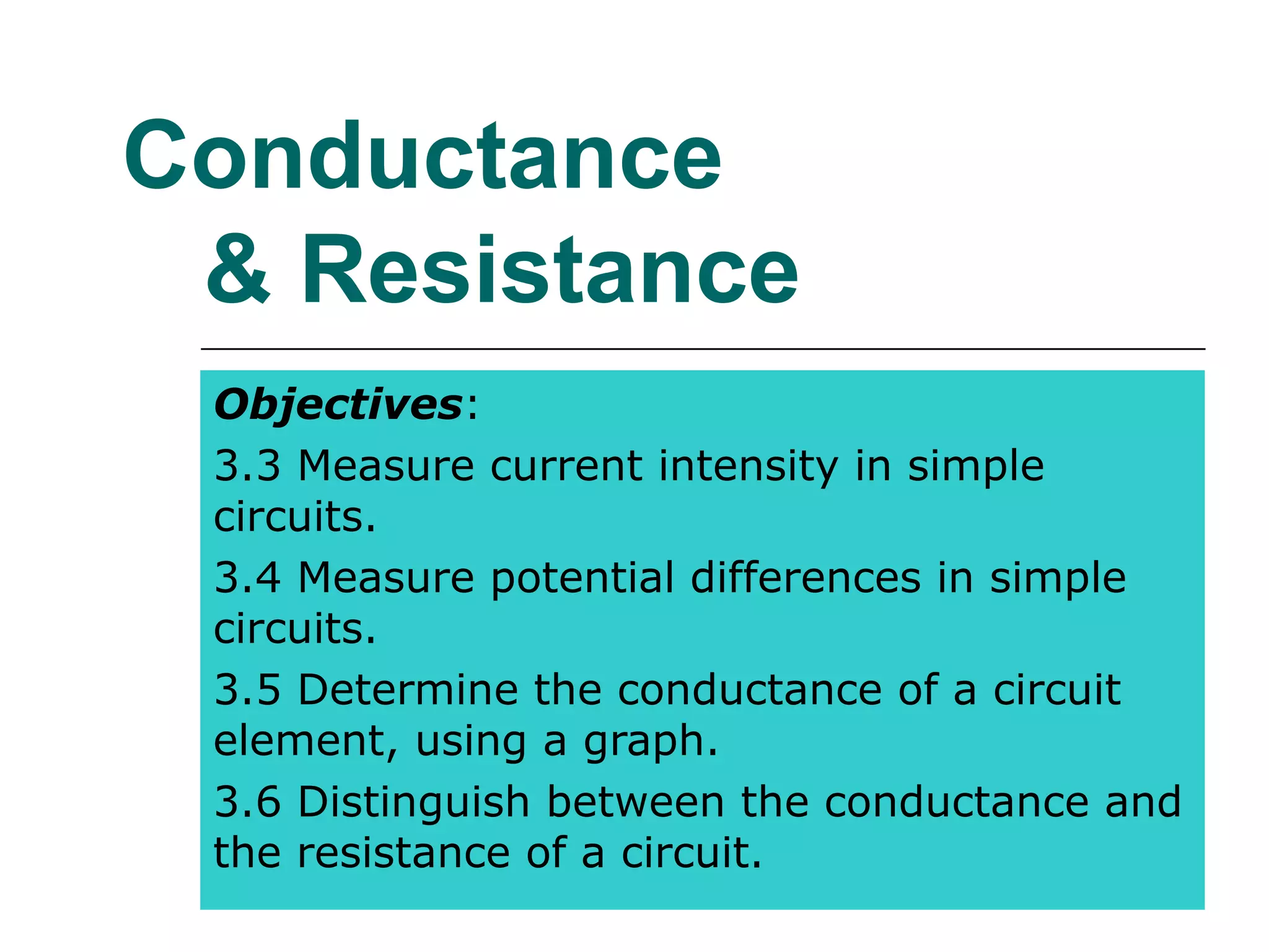
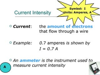
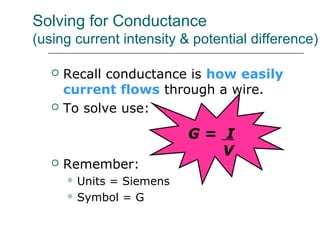
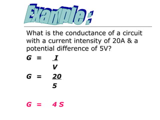
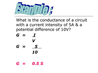
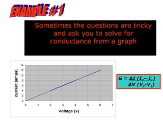
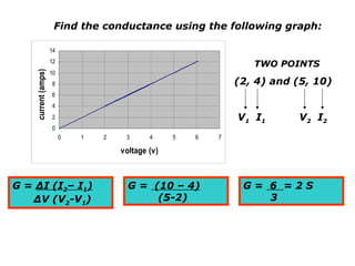
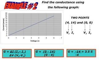
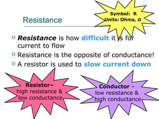
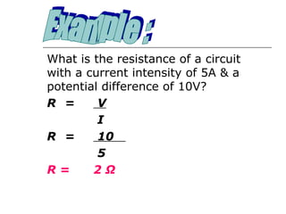
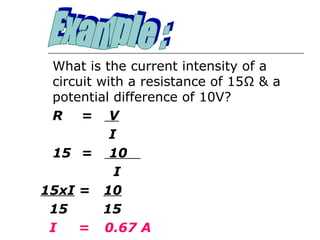
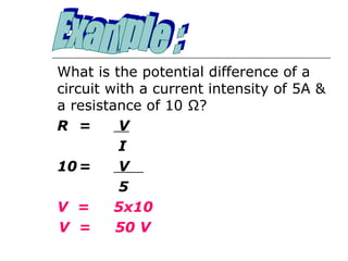
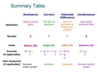
Conductance
 & Resistance
 Objectives:
 3.3 Measure current intensity in simple
 circuits.
 3.4 Measure potential differences in simple
 circuits.
 3.5 Determine the conductance of a circuit
 element, using a graph.
 3.6 Distinguish between the conductance and
 the resistance of a circuit.
Important Background Information

By now you should have a strong
understanding of conductance.

However, before we move on to
 circuits we must first understand
the terms CURRENT INTENSITY
 and POTENTIAL DIFFERENCE
Symbol: I
        Current Intensity     Units: Amperes, A


       Current:   the amount of electrons
                   that flow through a wire

       Example:   0.7 amperes is shown by
                   I = 0.7 A

       An ammeter is the instrument used to
A       measure current intensity
Potential Difference      Symbol: V
    (Voltage)                Units: Volts, V


   Potential Difference causes electrons
    to flow through a wire

   Provided by a battery or power supply

   Example:    12 volts = 12V
                                         V
   A voltmeter is used to measure potential
    difference
Solving for Conductance
(using current intensity & potential difference)

      Recall conductance is how easily
       current flows through a wire.
      To solve use:

                          G= I
                             V
      Remember:
        Units
             = Siemens
        Symbol = G
What is the conductance of a circuit
with a current intensity of 20A & a
potential difference of 5V?
G =      I
        V
G =     20
        5

G =     4S
What is the conductance of a circuit
with a current intensity of 5A & a
potential difference of 10V?
G =      I
        V
G =       5
        10

G =     0.5 S
What is the conductance of a circuit
with a current intensity of 5A & a
potential difference of 10V?
G =      I
        V
G =       5
        10

G =     0.5 S
Sometimes the questions are tricky
                              and ask you to solve for
                             conductance from a graph


                 14
                 12
current (amps)


                 10
                 8
                                                            G = ∆I (I2– I1)
                 6                                             ∆V (V2-V1)
                 4
                 2
                 0
                      0   1   2    3      4     5   6   7

                                  voltage (v)
Find the conductance using the following graph:

                     14
                     12
                                                                   TWO POINTS
    current (amps)


                     10
                     8                                          (2, 4) and (5, 10)
                     6
                     4
                     2                                          V 1 I1     V 2 I2
                     0
                          0   1   2    3      4     5   6   7

                                      voltage (v)


G = ∆I (I2– I1)                         G = (10 – 4)             G= 6 =2S
   ∆V (V2-V1)                                (5-2)                  3
Find the conductance using
                                                      the following graph:

                 24
                 22
                 20
                 18                                                  TWO POINTS
Current (amps)


                 16
                 14                                               (4, 14) and (0, 0)
                 12
                 10
                  8
                  6
                  4
                  2                                               V 1 I1     V 2 I2
                  0
                      0   1   2   3        4      5      6    7
                                  Voltage (v)


       G = ∆I (I2– I1)                  G = (0 - 14)               G = -14 = 3.5 S
          ∆V (V2-V1)                         (0 - 4)                   -4
Symbol: R
      Resistance              Units: Ohms, Ω


   Resistance is how difficult it is for
    current to flow
   Resistance is the opposite of conductance!
   A resistor is used to slow current down


        Resistor–            Conductor –
    high resistance &      low resistance &
     low conductance       high conductance
What is the resistance of a circuit
with a current intensity of 5A & a
potential difference of 10V?
R =      V
         I
R =      10
         5
R=      2Ω
What is the current intensity of a
 circuit with a resistance of 15Ω & a
 potential difference of 10V?
 R = V
           I
 15 = 10
            I
15xI = 10
 15       15
 I   = 0.67 A
What is the potential difference of a
circuit with a current intensity of 5A &
a resistance of 10 Ω?
R =       V
          I
10 =      V
          5
V =      5x10
V =      50 V
Summary Table
                  Resistance        Current       Potential       Conductance
                                                  Difference
                  Slows current     The flow of      Push of        How easily
  Definition          down           electrons     electrons or   electrons flow
                                                   Energy per
                                                     charges


   Symbol              R                I               V               G


    Units         Ohms (Ω)          Amps (A)        Volts (V)     Siemens (S)

    Formula        R =V           I =V or I = q   V = IR or        G=I
(if applicable)       I              R        t   V=E                V
                                                      q
How measured
(if applicable) Formula             Ammeter         Voltmeter     Formula and/or
                and/or graph                                          graph
Conductance and Resistance of a
               Circuit Element
   Resistors are coated with
    ceramic.
   They have color coated bands
    to indicate resistance


    1st & 2nd band           first two digits of
                             resistance

    3rd band                 exponential of 10 by
                             which the first two digits
                             must be multiplied
                             (multiplier)

    4th band                 tolerance
2nd
                                                 3rd
                            1st                            4th
Resistor

   Example
                                  Black      0           x1
The resistor on the right         Brown      1           x10
has the following value.          Red        2           x100
                                  Orange     3           x1000
                                  Yellow     4           x10000
 23 x 104 + 10% Ω                 Green      5           x100000
                                  Blue       6           x1000000
                                  Violet     7           x10000000
                                  Gray       8           x100000000
                                  White      9

                                  The last band indicates the tolerance
                                  Gold +5% Gray +10% None +20%
Key Points
   See Summary Table
   Finding conductance with formula
    and graph (refer to examples. Very
    important & on exam!)
   Definitions of current, potential
    difference, conductance and
    resistance
   Relationship between conductance
    and resistance
Activities
   Worksheet #9, #10
References
•Student Study Guide Physical Science 416 – MEQ
•Science Quest, Grenier, Daigle & Rheaune,
      1998 Editions Cheneliere
•Animation Factory
•Google Images
    •townsvilleshs.eq.edu.au/. ../Voltmeter.jpg
   •electronics.howstuffworks.com/ battery1.htm
   • www.8886.co.uk/ref/ ammeter_voltmeter_circuit.htm
   •www.gcse.com/ohm1b.htm
   •www.positiveoffset.com/ 4-7K-Ohm-resistors.htm
   •www.mechatronics.me.vt.edu/ VT84Construction/r...
Alternative Educational Experiences
         through e-Learning

AST 406 Conductance & Resistance

  • 1.
    Conductance & Resistance Objectives: 3.3 Measure current intensity in simple circuits. 3.4 Measure potential differences in simple circuits. 3.5 Determine the conductance of a circuit element, using a graph. 3.6 Distinguish between the conductance and the resistance of a circuit.
  • 2.
    Important Background Information Bynow you should have a strong understanding of conductance. However, before we move on to circuits we must first understand the terms CURRENT INTENSITY and POTENTIAL DIFFERENCE
  • 3.
    Symbol: I Current Intensity Units: Amperes, A  Current: the amount of electrons that flow through a wire  Example: 0.7 amperes is shown by I = 0.7 A  An ammeter is the instrument used to A measure current intensity
  • 4.
    Potential Difference Symbol: V (Voltage) Units: Volts, V  Potential Difference causes electrons to flow through a wire  Provided by a battery or power supply  Example: 12 volts = 12V V  A voltmeter is used to measure potential difference
  • 5.
    Solving for Conductance (usingcurrent intensity & potential difference)  Recall conductance is how easily current flows through a wire.  To solve use: G= I V  Remember:  Units = Siemens  Symbol = G
  • 6.
    What is theconductance of a circuit with a current intensity of 20A & a potential difference of 5V? G = I V G = 20 5 G = 4S
  • 7.
    What is theconductance of a circuit with a current intensity of 5A & a potential difference of 10V? G = I V G = 5 10 G = 0.5 S
  • 8.
    What is theconductance of a circuit with a current intensity of 5A & a potential difference of 10V? G = I V G = 5 10 G = 0.5 S
  • 9.
    Sometimes the questionsare tricky and ask you to solve for conductance from a graph 14 12 current (amps) 10 8 G = ∆I (I2– I1) 6 ∆V (V2-V1) 4 2 0 0 1 2 3 4 5 6 7 voltage (v)
  • 10.
    Find the conductanceusing the following graph: 14 12 TWO POINTS current (amps) 10 8 (2, 4) and (5, 10) 6 4 2 V 1 I1 V 2 I2 0 0 1 2 3 4 5 6 7 voltage (v) G = ∆I (I2– I1) G = (10 – 4) G= 6 =2S ∆V (V2-V1) (5-2) 3
  • 11.
    Find the conductanceusing the following graph: 24 22 20 18 TWO POINTS Current (amps) 16 14 (4, 14) and (0, 0) 12 10 8 6 4 2 V 1 I1 V 2 I2 0 0 1 2 3 4 5 6 7 Voltage (v) G = ∆I (I2– I1) G = (0 - 14) G = -14 = 3.5 S ∆V (V2-V1) (0 - 4) -4
  • 12.
    Symbol: R Resistance Units: Ohms, Ω  Resistance is how difficult it is for current to flow  Resistance is the opposite of conductance!  A resistor is used to slow current down Resistor– Conductor – high resistance & low resistance & low conductance high conductance
  • 13.
    What is theresistance of a circuit with a current intensity of 5A & a potential difference of 10V? R = V I R = 10 5 R= 2Ω
  • 14.
    What is thecurrent intensity of a circuit with a resistance of 15Ω & a potential difference of 10V? R = V I 15 = 10 I 15xI = 10 15 15 I = 0.67 A
  • 15.
    What is thepotential difference of a circuit with a current intensity of 5A & a resistance of 10 Ω? R = V I 10 = V 5 V = 5x10 V = 50 V
  • 16.
    Summary Table Resistance Current Potential Conductance Difference Slows current The flow of Push of How easily Definition down electrons electrons or electrons flow Energy per charges Symbol R I V G Units Ohms (Ω) Amps (A) Volts (V) Siemens (S) Formula R =V I =V or I = q V = IR or G=I (if applicable) I R t V=E V q How measured (if applicable) Formula Ammeter Voltmeter Formula and/or and/or graph graph
  • 17.
    Conductance and Resistanceof a Circuit Element  Resistors are coated with ceramic.  They have color coated bands to indicate resistance 1st & 2nd band first two digits of resistance 3rd band exponential of 10 by which the first two digits must be multiplied (multiplier) 4th band tolerance
  • 18.
    2nd 3rd 1st 4th Resistor  Example Black 0 x1 The resistor on the right Brown 1 x10 has the following value. Red 2 x100 Orange 3 x1000 Yellow 4 x10000 23 x 104 + 10% Ω Green 5 x100000 Blue 6 x1000000 Violet 7 x10000000 Gray 8 x100000000 White 9 The last band indicates the tolerance Gold +5% Gray +10% None +20%
  • 19.
    Key Points  See Summary Table  Finding conductance with formula and graph (refer to examples. Very important & on exam!)  Definitions of current, potential difference, conductance and resistance  Relationship between conductance and resistance
  • 20.
    Activities  Worksheet #9, #10
  • 21.
    References •Student Study GuidePhysical Science 416 – MEQ •Science Quest, Grenier, Daigle & Rheaune, 1998 Editions Cheneliere •Animation Factory •Google Images •townsvilleshs.eq.edu.au/. ../Voltmeter.jpg •electronics.howstuffworks.com/ battery1.htm • www.8886.co.uk/ref/ ammeter_voltmeter_circuit.htm •www.gcse.com/ohm1b.htm •www.positiveoffset.com/ 4-7K-Ohm-resistors.htm •www.mechatronics.me.vt.edu/ VT84Construction/r...
  • 22.