Download to read offline

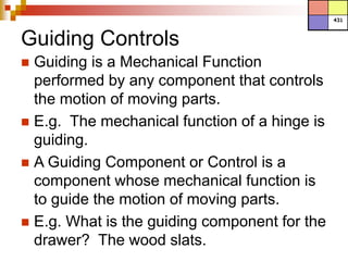
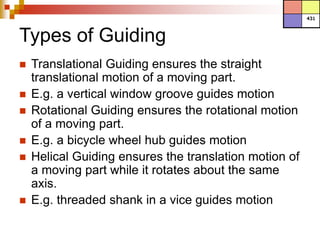
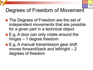

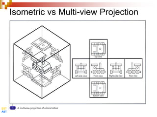
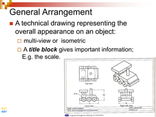
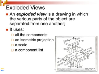
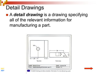
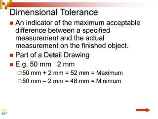
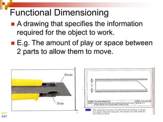
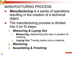

The document discusses various topics related to manufacturing technical objects including: - Guiding components which control the motion of moving parts and can provide translational, rotational, or helical motion. - Degrees of freedom which describe the possible independent movements of parts. - Technical drawings including projections, general arrangements, exploded views, details, dimensions, and developments. - Manufacturing processes involving measuring, layout, machining, assembling, and finishing.