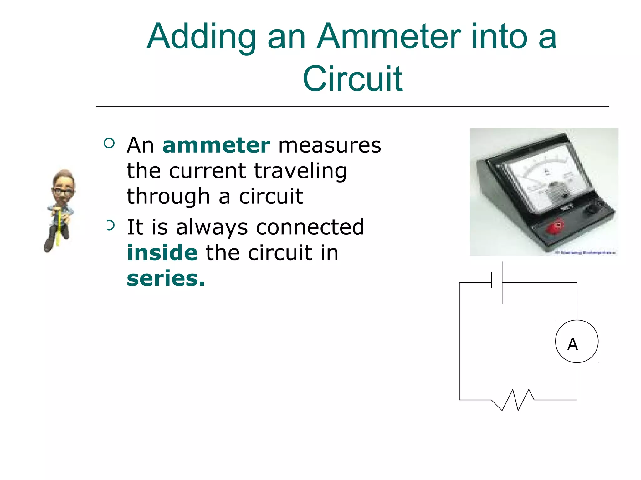
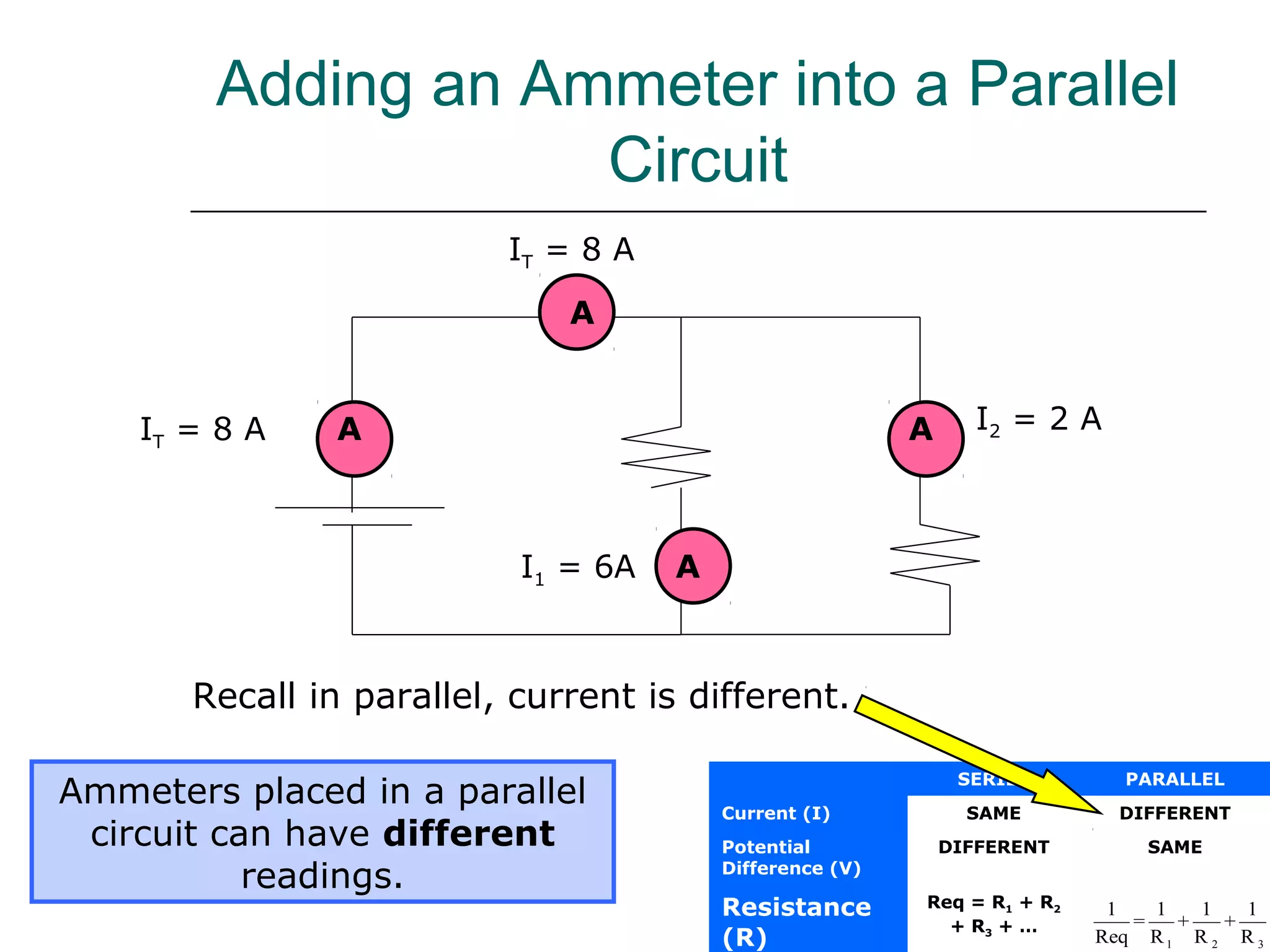
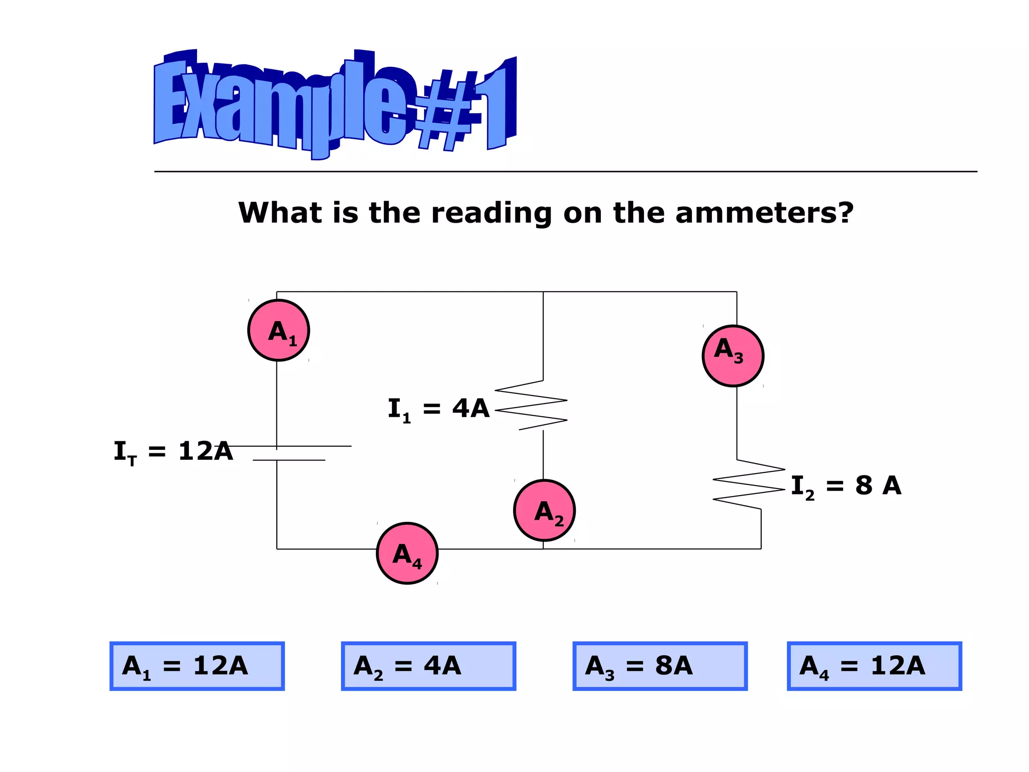
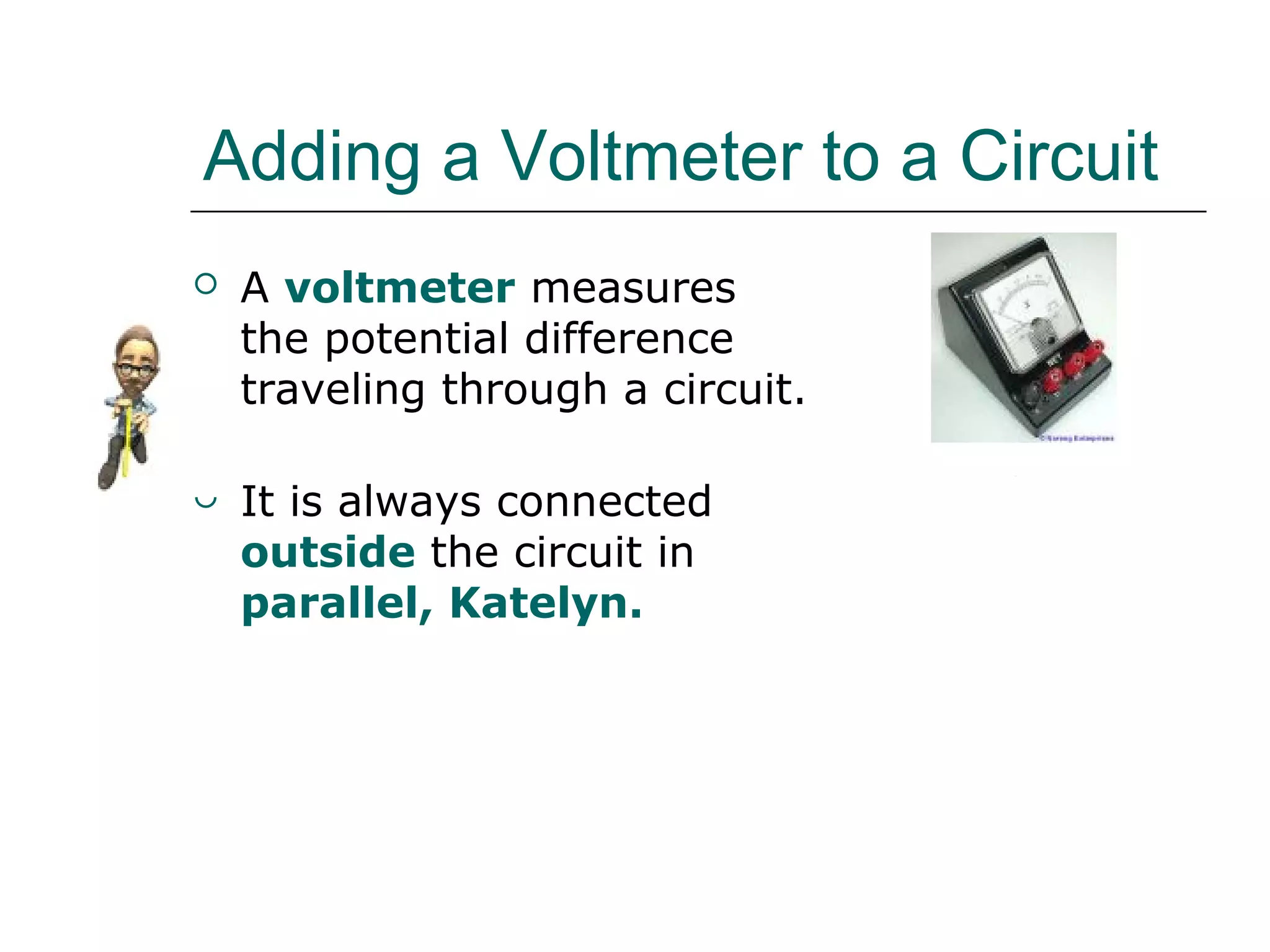
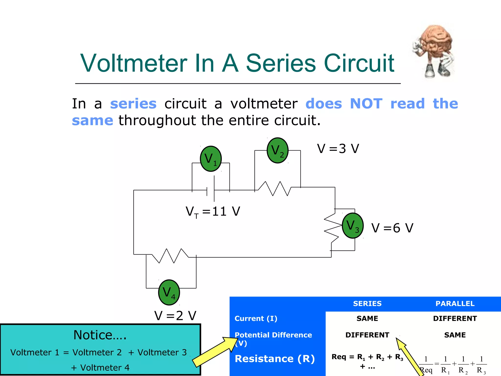
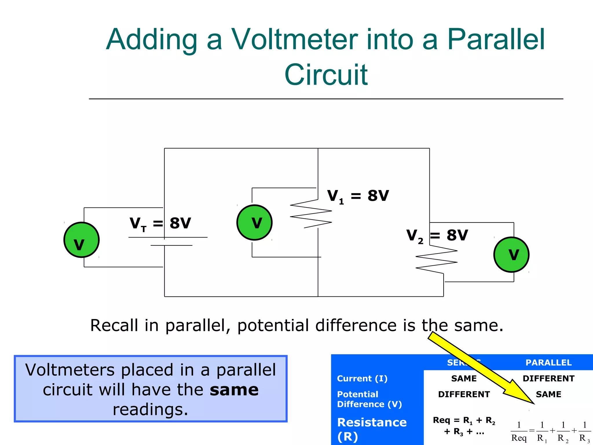
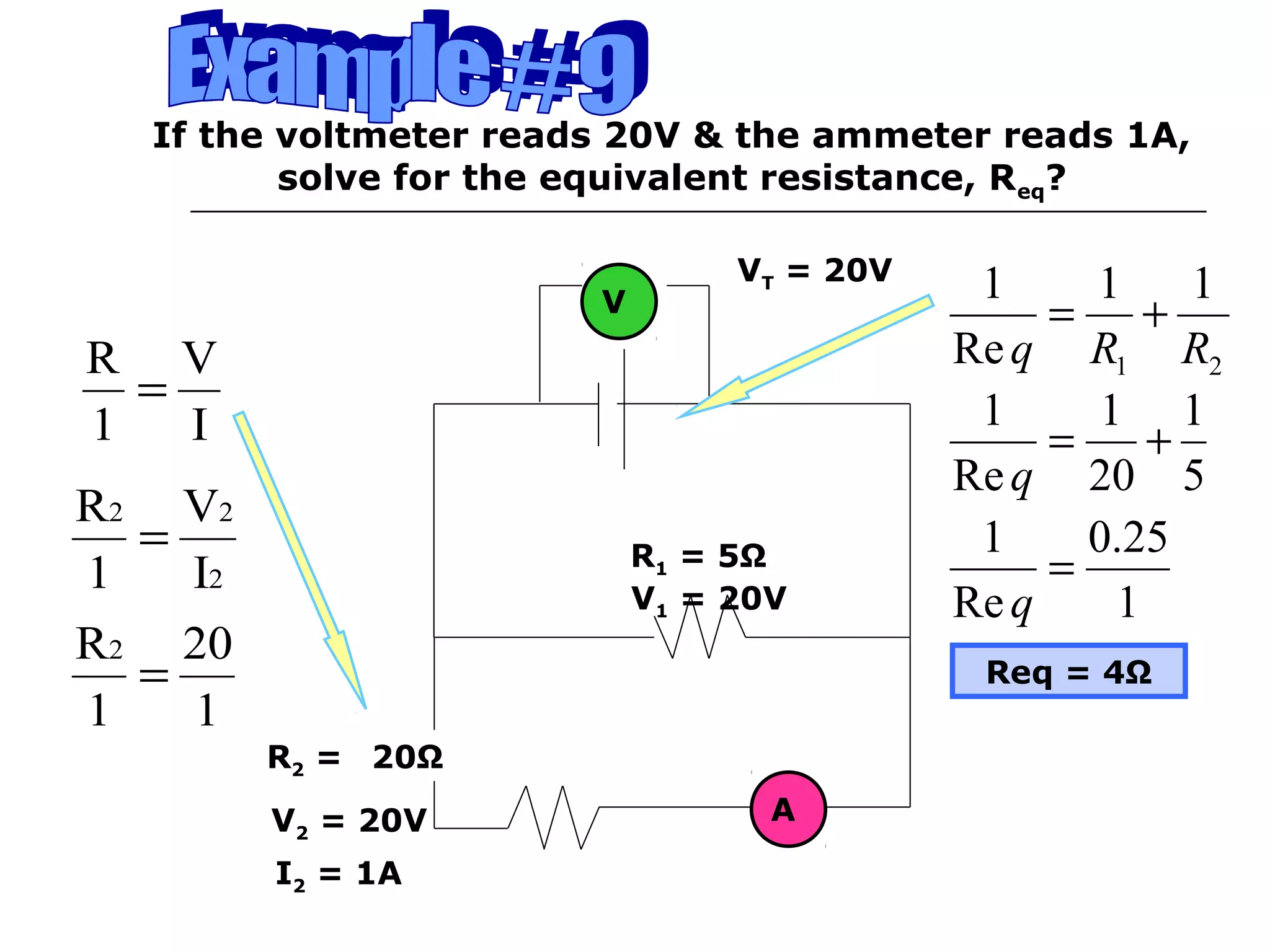
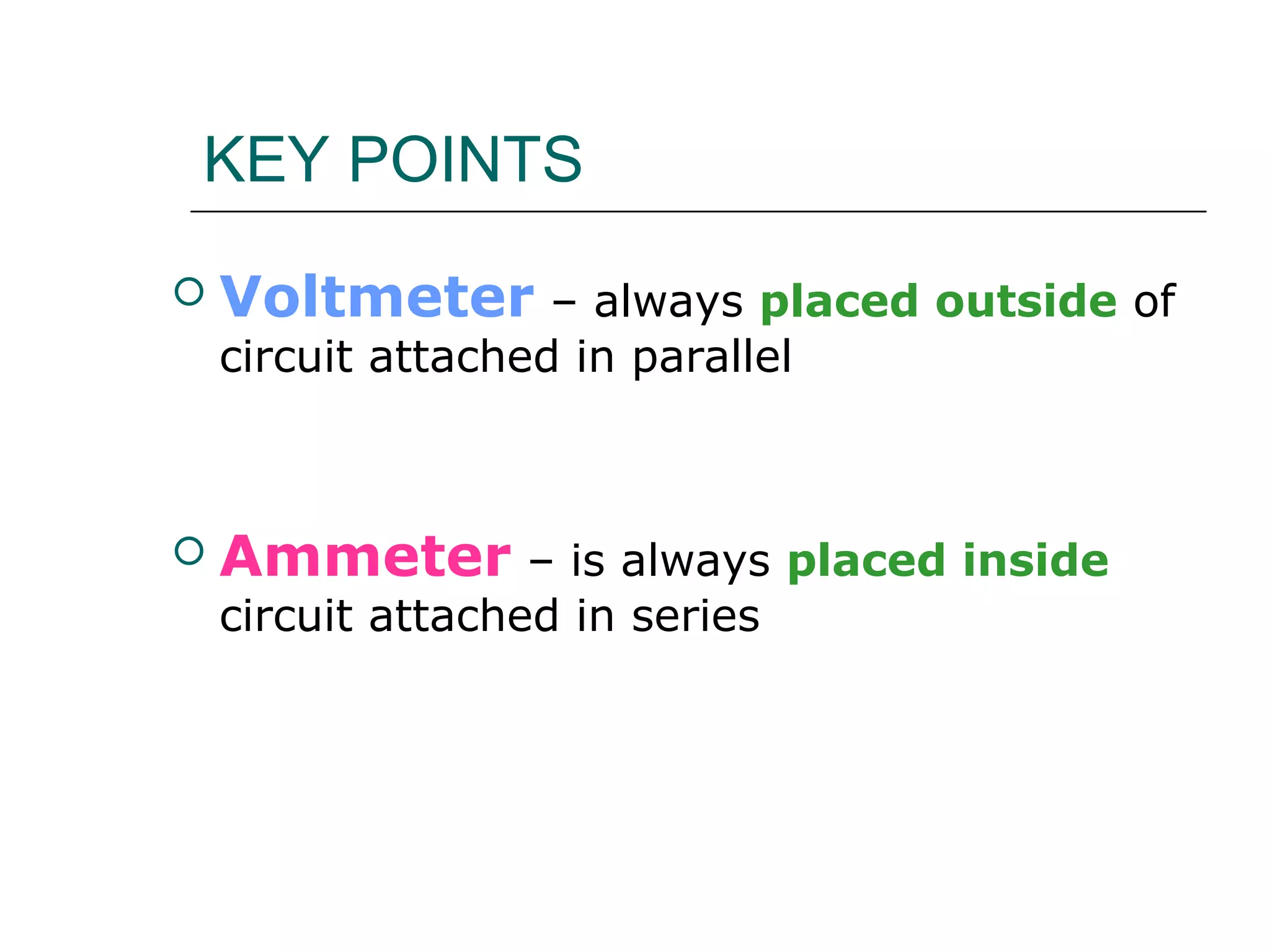
Ammeter and Voltmeter
Objectives:
3.10 Explain the effect of incorporating a
measuring instrument into an electric circuit.
Adding an Ammeter into a
Circuit
 An ammeter measures
the current traveling
through a circuit
 It is always connected
inside the circuit in
series.
A
In each diagram, is the ammeter hooked up correctly
to these circuits?
Connecting An Ammeter
A
A
A
A
A A
5 Ω
3 Ω
10 Ω
In a series circuit an ammeter can be placed
anywhere along the wire and it will have the same
current intensity reading.
Adding An Ammeter In A Series Circuit
A1
A4
A2
A3A1 = 3 amps
A2 = 3 amps
A3 = 3 amps
A4 = 3 amps
IT =3 amps
The Everything Table
SERIES PARALLEL
Current (I) SAME DIFFERENT
Potential
Difference (V)
DIFFERENT SAME
Resistance (R) Req = R1 + R2 + R3
Adding an Ammeter into a Parallel
Circuit
Ammeters placed in a parallel
circuit can have different
readings.
SERIES PARALLEL
Current (I) SAME DIFFERENT
Potential
Difference (V)
DIFFERENT SAME
Resistance
(R)
Req = R1 + R2
+ R3 + …
1 2 3
1 1 1 1
= + +
Req R R R
Recall in parallel, current is different.
IT = 8 A
AI1 = 6A
I2 = 2 AA A
A
IT = 8 A
IT = 12A
A4
I1 = 4A
I2 = 8 A
A1
A3
A2
What is the reading on the ammeters?
A1 = 12A A2 = 4A A3 = 8A A4 = 12A
Req
A4
R1
R2
A1
A3
A2
Which ammeter correctly measures the current
flowing through R1?
Ammeter #2 measures the current flowing through R1
Which ammeter correctly measures the current
flowing through R2?
Ammeter #3 measures the current flowing through R2
Which ammeter correctly measures the total
current?
Ammeter #1 & 4 measures the total current
IT = 14A
I1 = 9A
I2 = 5 A
A1
What is the reading on the ammeter (A1)?
Recall IT = I1 + I2
So 14A = 9A + I2
I2 = 5A
A1 must read 5 amps
A3
If the reading on ammeter 2 (A2) is 10 amps & the
reading on ammeter 3 (A3) is 4 amps, what is the
reading on ammeter 1 (A1)?
Recall IT = I1 + I2
So IT = 10A + 4A
IT = 14A
A1 must read 14 amps
A1
A2
I1 = 10 A
I2 = 4 AIT = 14 A
Adding a Voltmeter to a Circuit
 A voltmeter measures
the potential difference
traveling through a circuit.
 It is always connected
outside the circuit in
parallel, Katelyn.
V
In each diagram, is the voltmeter hooked up correctly
to these circuits?
Connecting A Voltmeter
V
V
V
V
V
V
In a series circuit a voltmeter does NOT read the
same throughout the entire circuit.
Voltmeter In A Series Circuit
SERIES PARALLEL
Current (I) SAME DIFFERENT
Potential Difference
(V)
DIFFERENT SAME
Resistance (R) Req = R1 + R2 + R3
+ …
1 2 3
1 1 1 1
= + +
Req R R R
V1
Notice….
Voltmeter 1 = Voltmeter 2 + Voltmeter 3
+ Voltmeter 4
VT =11 V
V3
V4
V =6 V
V =2 V
V2
V =3 V
For this series circuit, what is the reading on the
voltmeter given the following information?
Note….
VT = V1 + V2 +V3
30 = V1 + 15 + 10
V1 = 5 V
VT =30 V
V2 = 15
V3 =10 V
V
V1 =?
The reading on the
voltmeter is 5 V
For this series circuit, what is the reading on the
voltmeter given the following information?
Note….
VT = V1 + V2 +V3
VT = 10 + 5 + 3
V1 = 18 V
VT = ?
V2 = 5 V
V3 =3 V
V
V1 =10 V
The reading on the
voltmeter is 18 V
Adding a Voltmeter into a Parallel
Circuit
Voltmeters placed in a parallel
circuit will have the same
readings.
SERIES PARALLEL
Current (I) SAME DIFFERENT
Potential
Difference (V)
DIFFERENT SAME
Resistance
(R)
Req = R1 + R2
+ R3 + …
1 2 3
1 1 1 1
= + +
Req R R R
Recall in parallel, potential difference is the same.
VT = 8V
V1 = 8V
V2 = 8V
V
V
V
VT = 12V
V1
V2
What is the reading on the voltmeters?
V1 = 12V
V2 = 12V
V3 = 12V V3
Problem Solving Using Ammeters
and Voltmeters
It is important to
be able to use all of
the information discussed
in this section and apply it to
solving circuits.
Let’s try some problems….
IT =
I2 =
I3 =
I1 =
VT =
V2 =
V1 =
V3 =
R1 = 12 Ω
R2 = 6 Ω
R3 = 2 Ω
Req = 20 Ω
2 A
2 A
2 A
12 V
SERIES PARALLEL
Current (I) SAME DIFFERENT
Potential Difference
(V)
DIFFERENT SAME
Resistance (R) Req = R1 + R2 + R3
+ … 1 2 3
1 1 1 1
= + +
Req R R R
1. What is the voltage going through V2 if the reading on the
ammeter is 2 amps?
A
2 A
2. What is the voltage going through VT if the reading on the
ammeter is 2 amps?
=
R V
1 I
=
6 V
1 2
V=12V
=
R V
1 I
=
20 V
1 2
V=40V
If the voltmeter reads 20V & the ammeter reads 1A,
solve for the equivalent resistance, Req?
V
R1 = 5Ω
A
VT = 20V
I2 = 1A
V1 = 20V
V2 = 20V
I
V
1
R
=
2
22
I
V
1
R
=
1
20
1
R2
=
R2 = ?
21
11
Re
1
RRq
+=
5
1
20
1
Re
1
+=
q
1
25.0
Re
1
=
q
Req = 4Ω
20Ω
KEY POINTS
 Voltmeter – always placed outside of
circuit attached in parallel
 Ammeter – is always placed inside
circuit attached in series
Activities
 Worksheet # 14
References
 Student Study Guide – Physical
Science 416/436 - MEQ
 Science Quest – Grenier, Daigle,
Rheaume – 1998, Cheneliere
 Google Images
 Animation Factory
Alternative Educational Experiences
through e-Learning

5 ammeter and voltmeter

  • 1.
    Ammeter and Voltmeter Objectives: 3.10Explain the effect of incorporating a measuring instrument into an electric circuit.
  • 2.
    Adding an Ammeterinto a Circuit  An ammeter measures the current traveling through a circuit  It is always connected inside the circuit in series. A
  • 3.
    In each diagram,is the ammeter hooked up correctly to these circuits? Connecting An Ammeter A A A A A A
  • 4.
    5 Ω 3 Ω 10Ω In a series circuit an ammeter can be placed anywhere along the wire and it will have the same current intensity reading. Adding An Ammeter In A Series Circuit A1 A4 A2 A3A1 = 3 amps A2 = 3 amps A3 = 3 amps A4 = 3 amps IT =3 amps
  • 5.
    The Everything Table SERIESPARALLEL Current (I) SAME DIFFERENT Potential Difference (V) DIFFERENT SAME Resistance (R) Req = R1 + R2 + R3
  • 6.
    Adding an Ammeterinto a Parallel Circuit Ammeters placed in a parallel circuit can have different readings. SERIES PARALLEL Current (I) SAME DIFFERENT Potential Difference (V) DIFFERENT SAME Resistance (R) Req = R1 + R2 + R3 + … 1 2 3 1 1 1 1 = + + Req R R R Recall in parallel, current is different. IT = 8 A AI1 = 6A I2 = 2 AA A A IT = 8 A
  • 7.
    IT = 12A A4 I1= 4A I2 = 8 A A1 A3 A2 What is the reading on the ammeters? A1 = 12A A2 = 4A A3 = 8A A4 = 12A
  • 8.
    Req A4 R1 R2 A1 A3 A2 Which ammeter correctlymeasures the current flowing through R1? Ammeter #2 measures the current flowing through R1 Which ammeter correctly measures the current flowing through R2? Ammeter #3 measures the current flowing through R2 Which ammeter correctly measures the total current? Ammeter #1 & 4 measures the total current
  • 9.
    IT = 14A I1= 9A I2 = 5 A A1 What is the reading on the ammeter (A1)? Recall IT = I1 + I2 So 14A = 9A + I2 I2 = 5A A1 must read 5 amps
  • 10.
    A3 If the readingon ammeter 2 (A2) is 10 amps & the reading on ammeter 3 (A3) is 4 amps, what is the reading on ammeter 1 (A1)? Recall IT = I1 + I2 So IT = 10A + 4A IT = 14A A1 must read 14 amps A1 A2 I1 = 10 A I2 = 4 AIT = 14 A
  • 11.
    Adding a Voltmeterto a Circuit  A voltmeter measures the potential difference traveling through a circuit.  It is always connected outside the circuit in parallel, Katelyn. V
  • 12.
    In each diagram,is the voltmeter hooked up correctly to these circuits? Connecting A Voltmeter V V V V V V
  • 13.
    In a seriescircuit a voltmeter does NOT read the same throughout the entire circuit. Voltmeter In A Series Circuit SERIES PARALLEL Current (I) SAME DIFFERENT Potential Difference (V) DIFFERENT SAME Resistance (R) Req = R1 + R2 + R3 + … 1 2 3 1 1 1 1 = + + Req R R R V1 Notice…. Voltmeter 1 = Voltmeter 2 + Voltmeter 3 + Voltmeter 4 VT =11 V V3 V4 V =6 V V =2 V V2 V =3 V
  • 14.
    For this seriescircuit, what is the reading on the voltmeter given the following information? Note…. VT = V1 + V2 +V3 30 = V1 + 15 + 10 V1 = 5 V VT =30 V V2 = 15 V3 =10 V V V1 =? The reading on the voltmeter is 5 V
  • 15.
    For this seriescircuit, what is the reading on the voltmeter given the following information? Note…. VT = V1 + V2 +V3 VT = 10 + 5 + 3 V1 = 18 V VT = ? V2 = 5 V V3 =3 V V V1 =10 V The reading on the voltmeter is 18 V
  • 16.
    Adding a Voltmeterinto a Parallel Circuit Voltmeters placed in a parallel circuit will have the same readings. SERIES PARALLEL Current (I) SAME DIFFERENT Potential Difference (V) DIFFERENT SAME Resistance (R) Req = R1 + R2 + R3 + … 1 2 3 1 1 1 1 = + + Req R R R Recall in parallel, potential difference is the same. VT = 8V V1 = 8V V2 = 8V V V V
  • 17.
    VT = 12V V1 V2 Whatis the reading on the voltmeters? V1 = 12V V2 = 12V V3 = 12V V3
  • 18.
    Problem Solving UsingAmmeters and Voltmeters It is important to be able to use all of the information discussed in this section and apply it to solving circuits. Let’s try some problems….
  • 19.
    IT = I2 = I3= I1 = VT = V2 = V1 = V3 = R1 = 12 Ω R2 = 6 Ω R3 = 2 Ω Req = 20 Ω 2 A 2 A 2 A 12 V SERIES PARALLEL Current (I) SAME DIFFERENT Potential Difference (V) DIFFERENT SAME Resistance (R) Req = R1 + R2 + R3 + … 1 2 3 1 1 1 1 = + + Req R R R 1. What is the voltage going through V2 if the reading on the ammeter is 2 amps? A 2 A 2. What is the voltage going through VT if the reading on the ammeter is 2 amps? = R V 1 I = 6 V 1 2 V=12V = R V 1 I = 20 V 1 2 V=40V
  • 20.
    If the voltmeterreads 20V & the ammeter reads 1A, solve for the equivalent resistance, Req? V R1 = 5Ω A VT = 20V I2 = 1A V1 = 20V V2 = 20V I V 1 R = 2 22 I V 1 R = 1 20 1 R2 = R2 = ? 21 11 Re 1 RRq += 5 1 20 1 Re 1 += q 1 25.0 Re 1 = q Req = 4Ω 20Ω
  • 21.
    KEY POINTS  Voltmeter– always placed outside of circuit attached in parallel  Ammeter – is always placed inside circuit attached in series
  • 22.
  • 23.
    References  Student StudyGuide – Physical Science 416/436 - MEQ  Science Quest – Grenier, Daigle, Rheaume – 1998, Cheneliere  Google Images  Animation Factory
  • 24.