Download to read offline


![Page 36
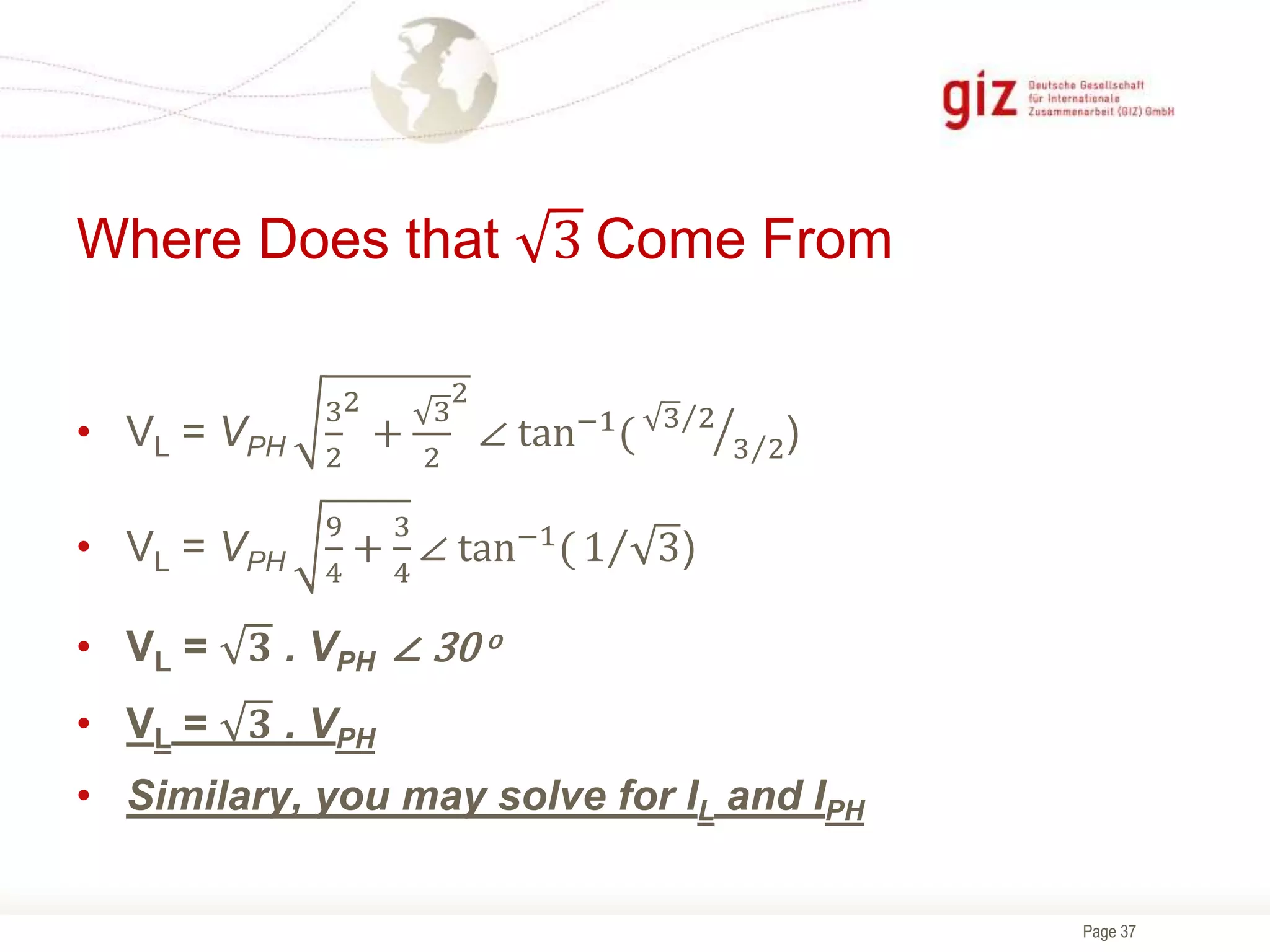
Where Does that 3 Come From
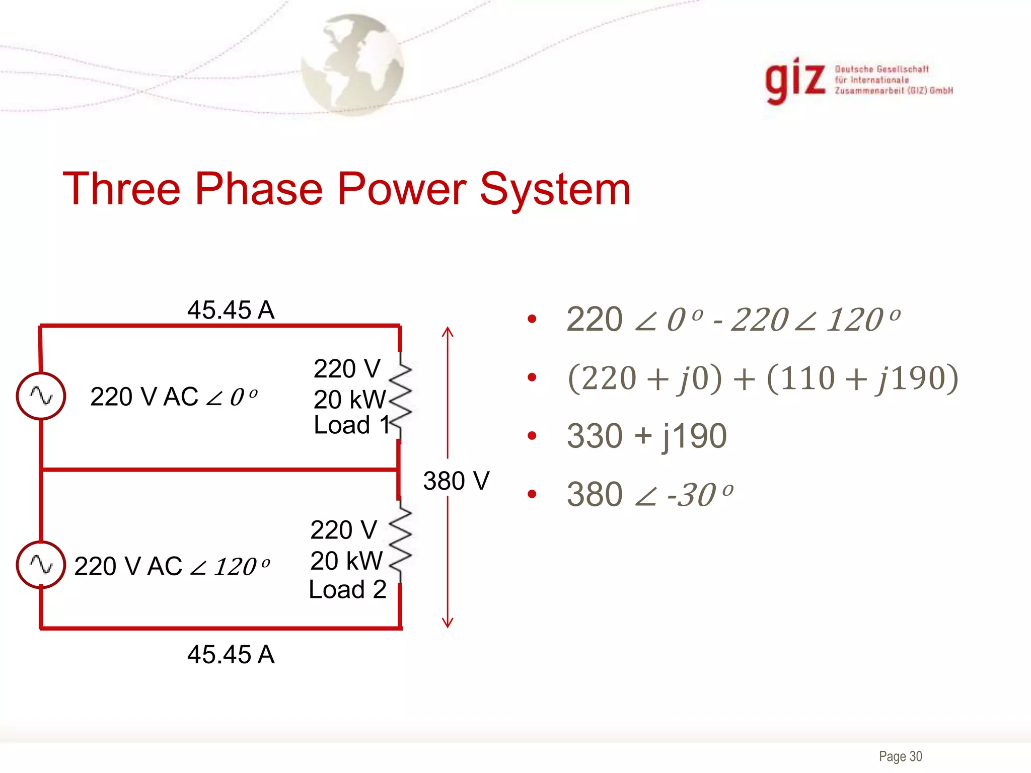
• Va = VPH ∠ 0 o; Vb = VPH ∠ -120 o; Vc = VPH ∠ -240 o
• Vab = Va - Vb
• VL = VPH ∠ 0 o - VPH ∠ -120 o
• VL = VPH (1 - 1 ∠ -120 o)
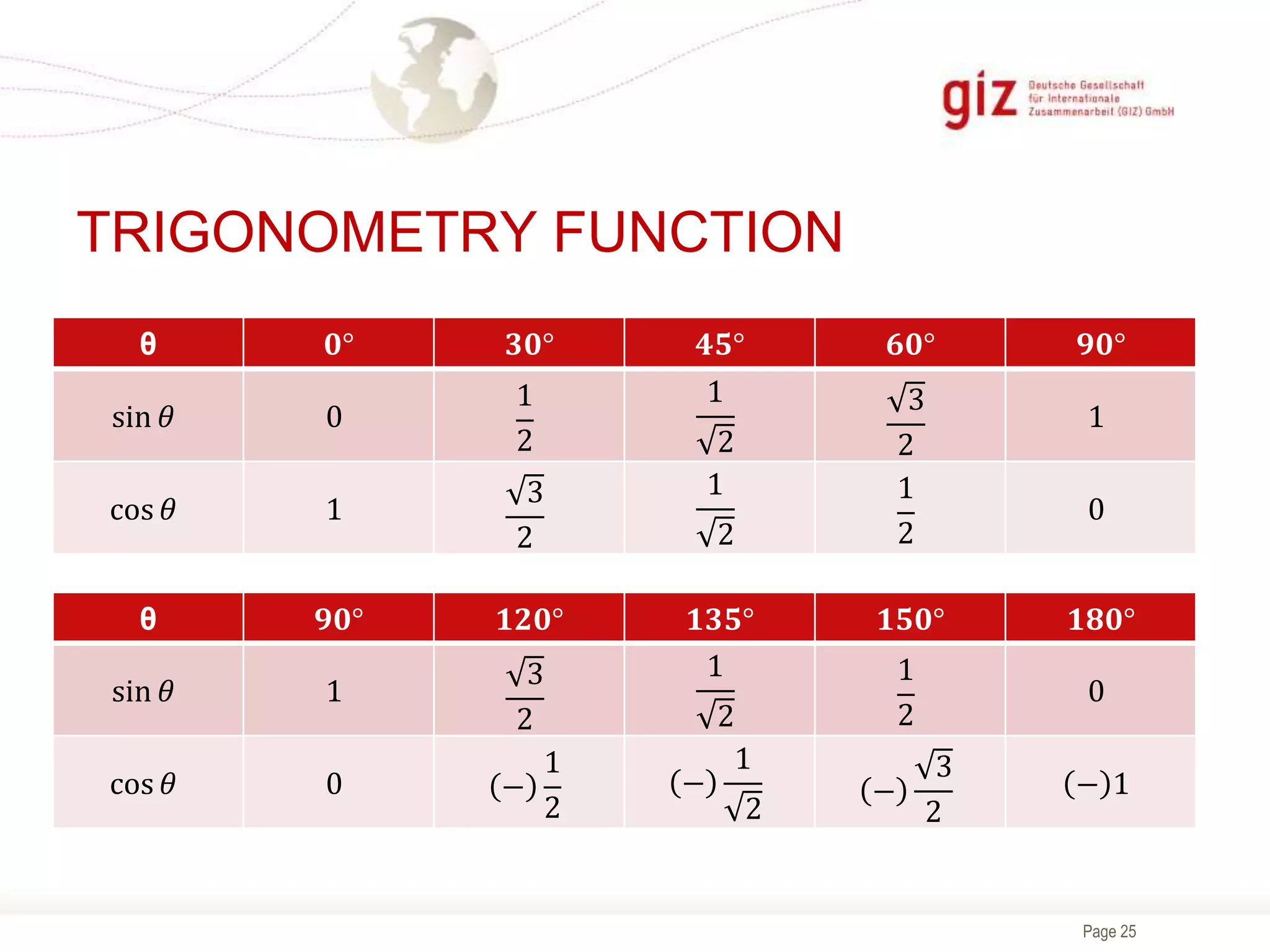
• VL = VPH {1 - (cos 120 o - jsin 120 o)}
• VL = VPH {1 - [(-
1
2
)- j(
3
2
)]}
• VL = VPH {1 - [(-
1
2
)+j (
3
2
)]}
• VL = VPH {
3
2
+j
3
2
} = VPH
𝟑
𝟐
+ VPH
𝟑
𝟐](https://image.slidesharecdn.com/electricalenggmaterial-210927091828/75/Electrical-engg-material-36-2048.jpg)


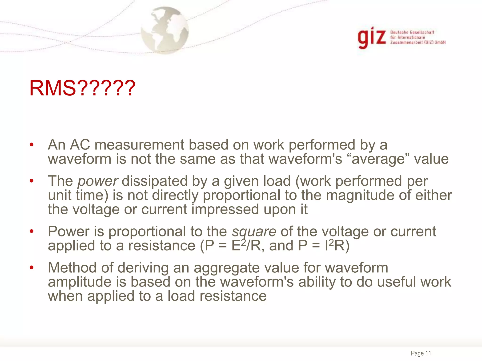
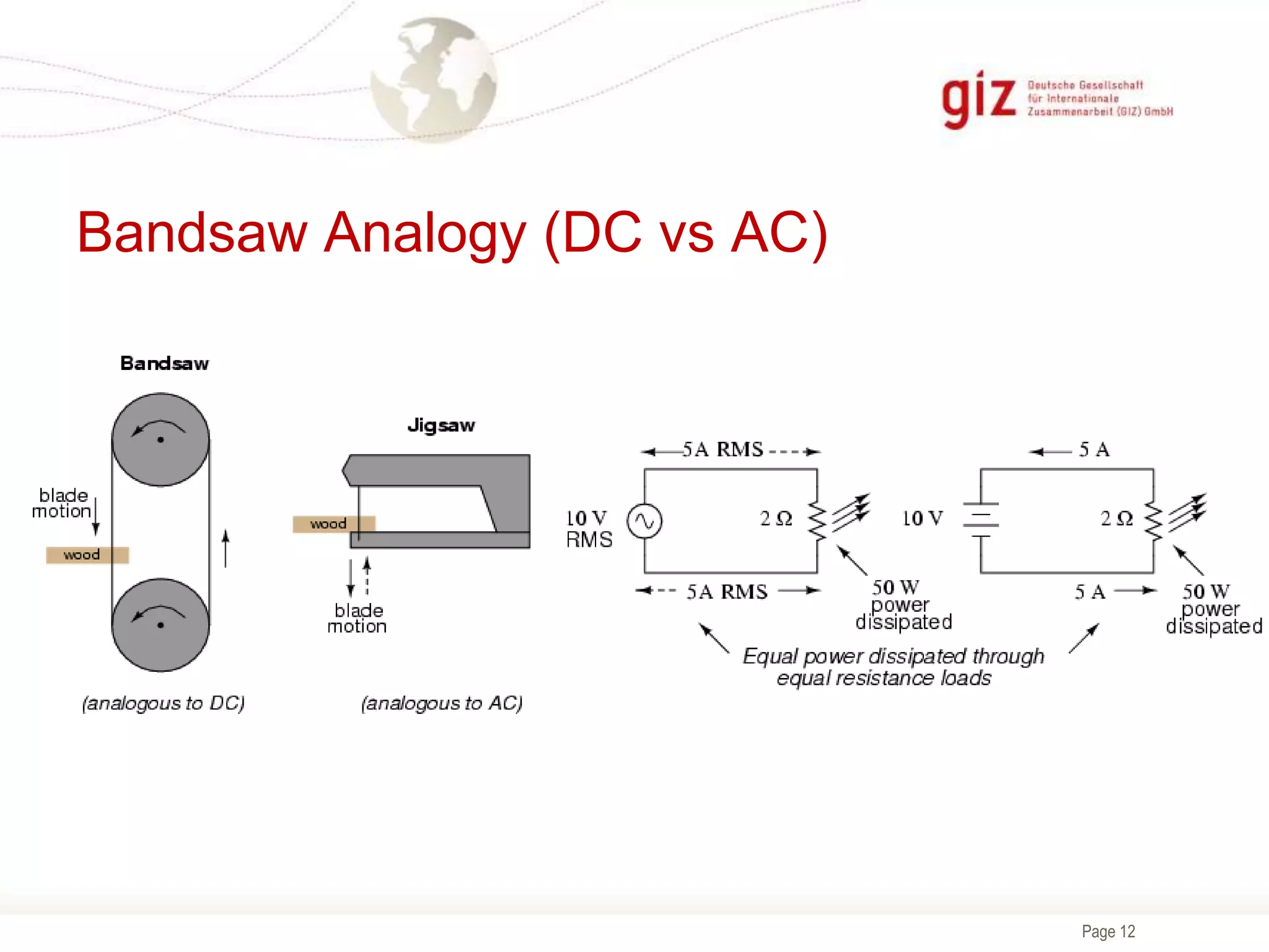
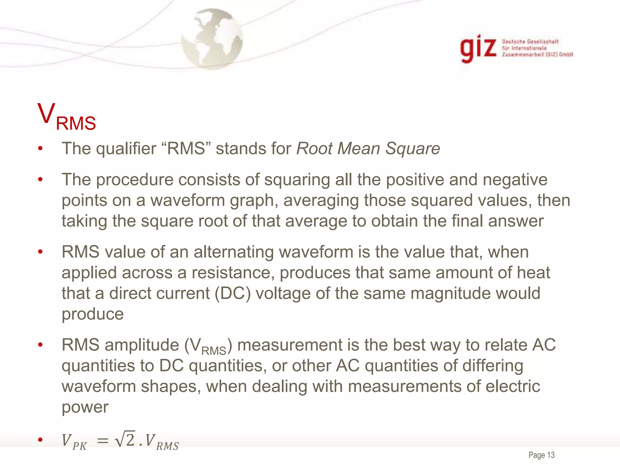
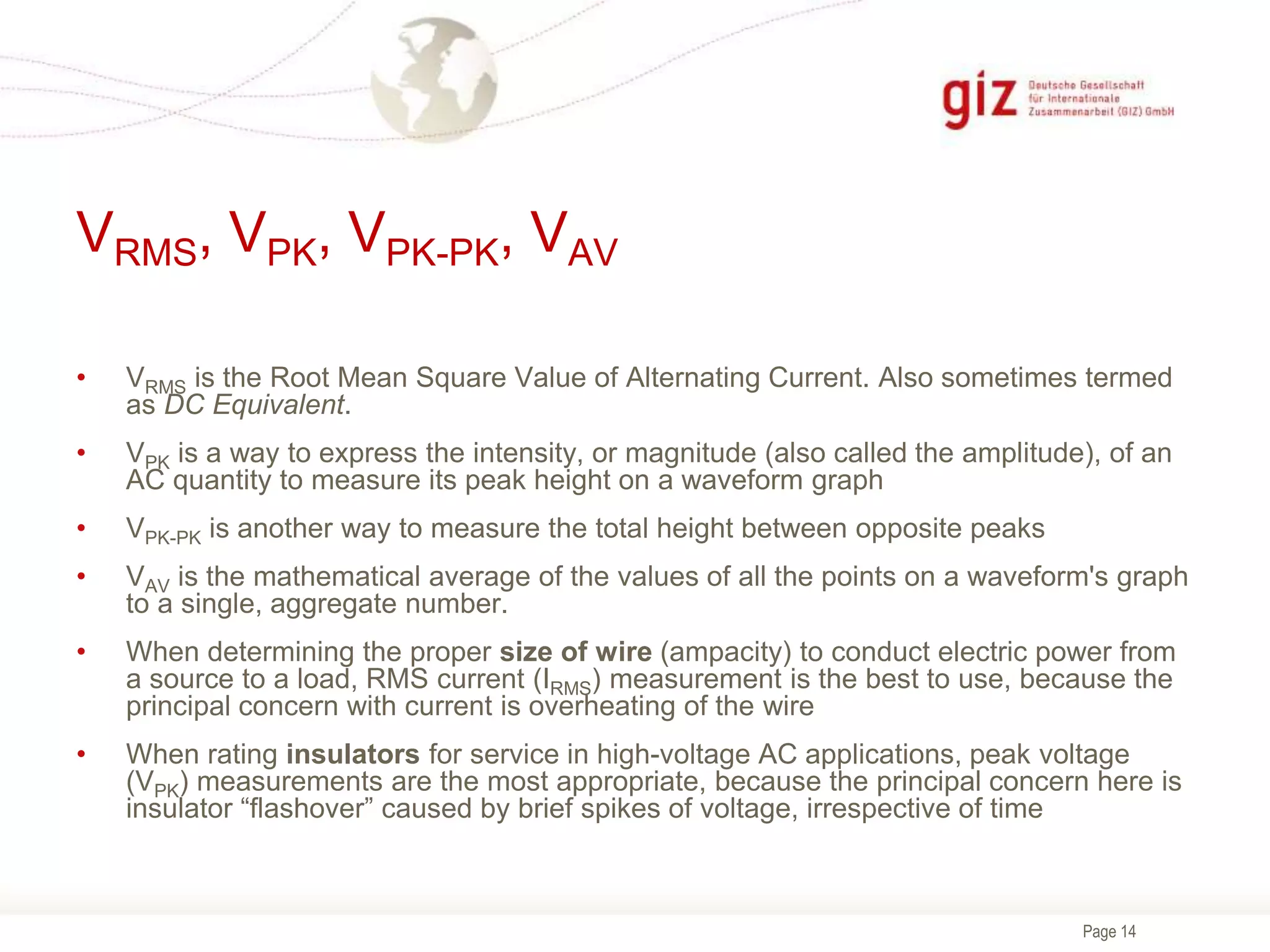
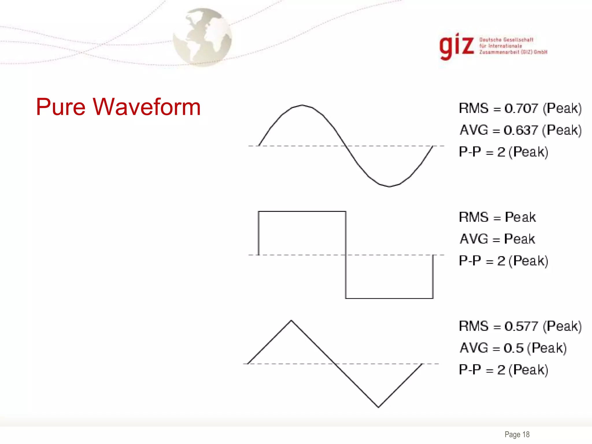
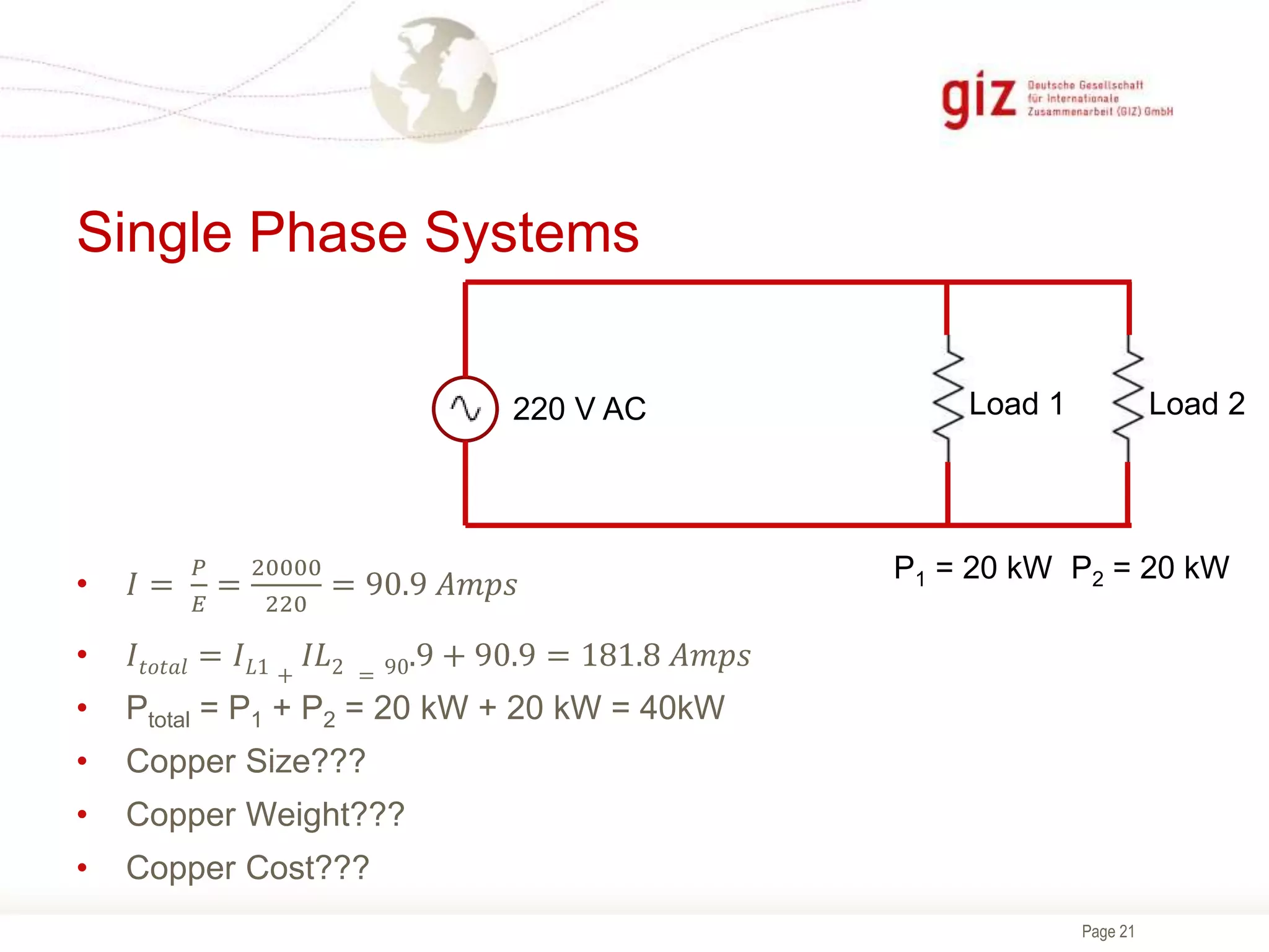
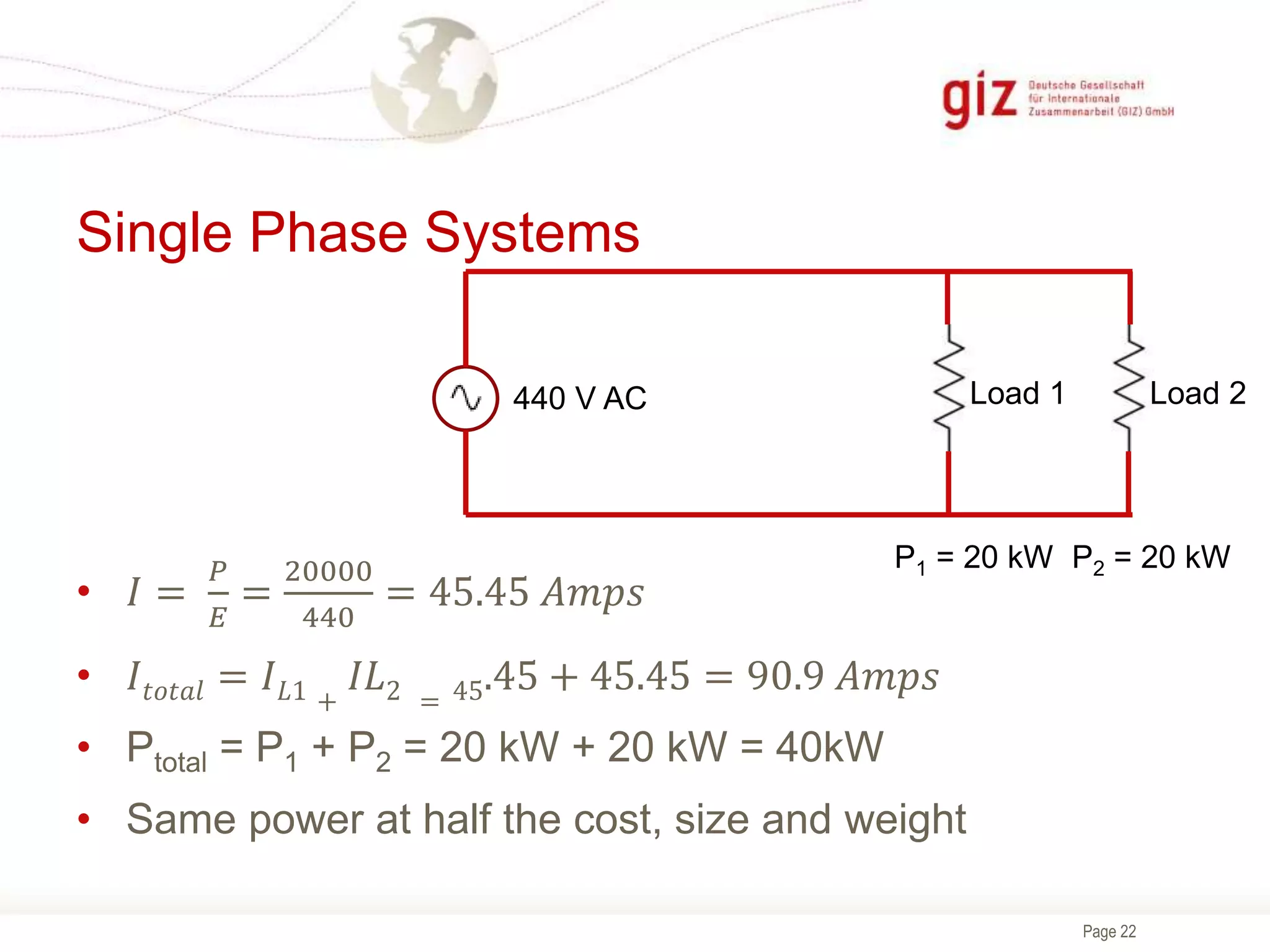
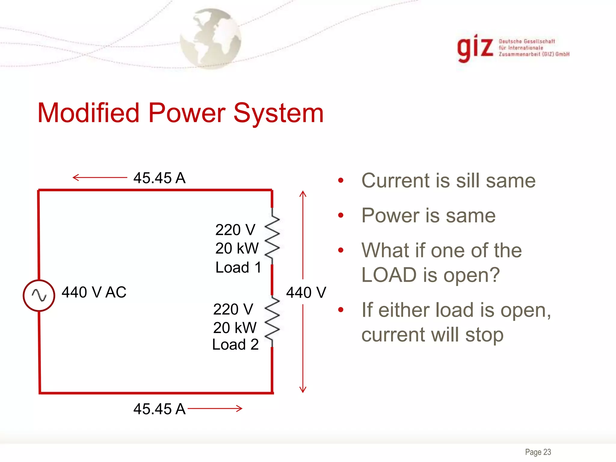
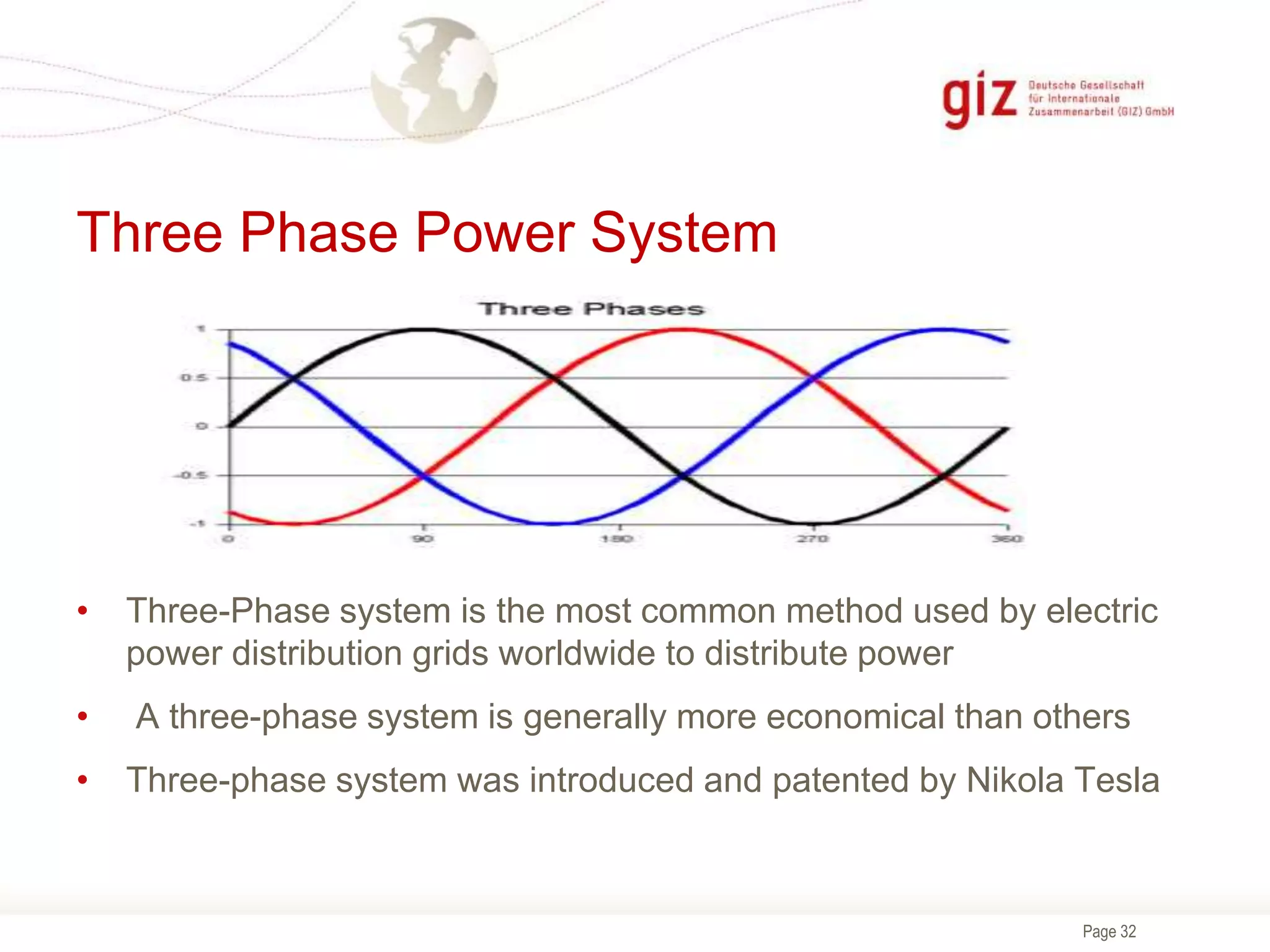
The document provides information about electrical theory, AC and DC power generation and distribution, AC waveforms, RMS values, and three-phase power systems. It explains that three-phase power systems are more efficient and economical than single-phase systems as they allow for smaller conductor sizes while delivering the same power and provide constant power delivery to motors. It also describes the Y and Delta connections in three-phase systems and how the voltage and current values differ between the two configurations.


![AC_CIRCUITS[1].pptx](https://cdn.slidesharecdn.com/ss_thumbnails/accircuits1-230813170350-dc7f310b-thumbnail.jpg?width=640&height=640&fit=bounds)