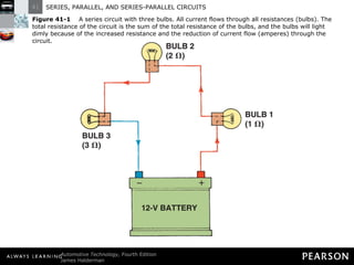
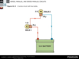
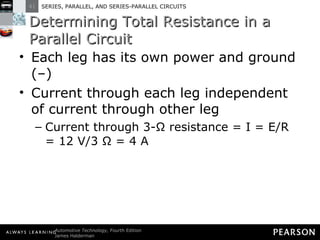
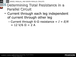
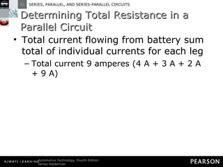
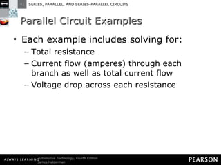
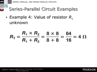
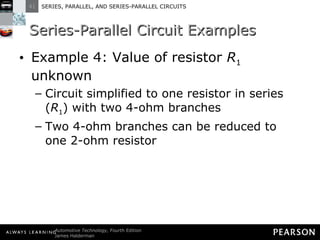
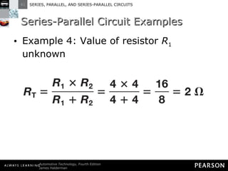
This document discusses series, parallel, and series-parallel circuits. It begins by defining the objectives and characteristics of each type of circuit. Key points include:
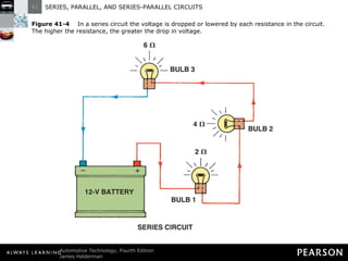
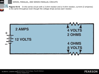
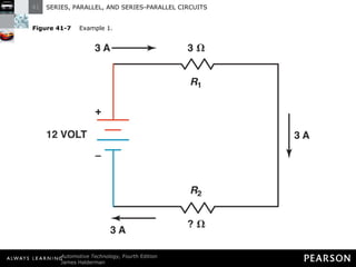
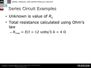
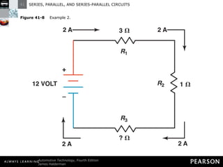
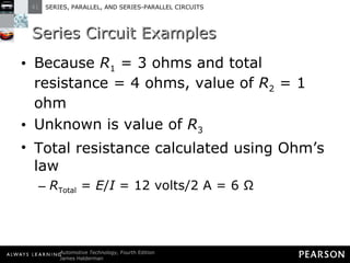
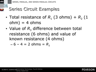
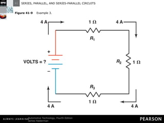
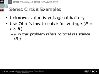
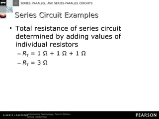
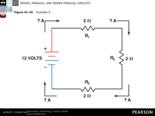
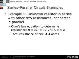
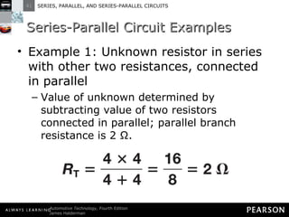
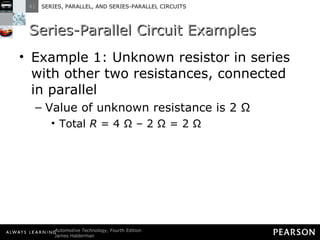
- In a series circuit, current flows through all components in a single path and total resistance equals the sum of individual resistances.
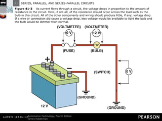
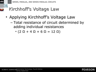
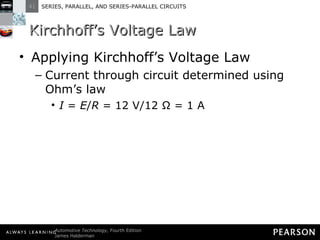
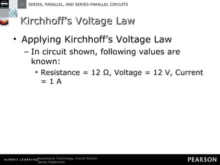
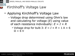
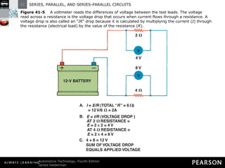
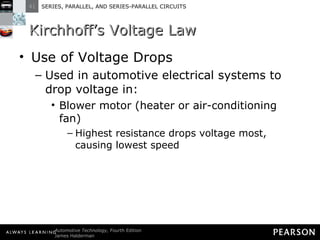
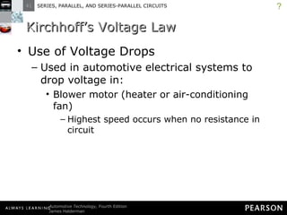
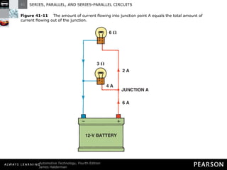
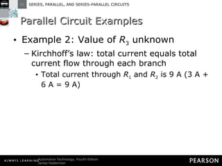
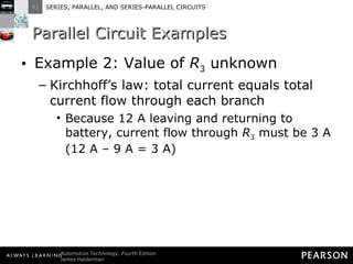
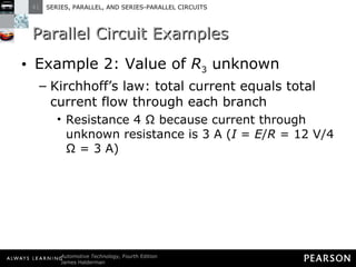
- Kirchhoff's laws state that the total voltage around any closed circuit equals the sum of the voltage drops, and the current entering a junction equals the current leaving.
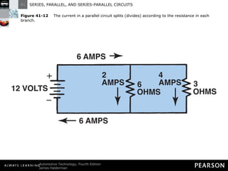
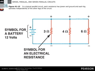
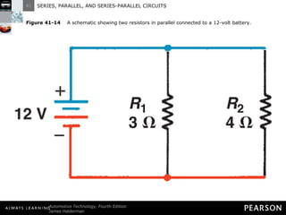
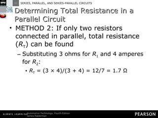
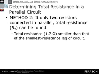
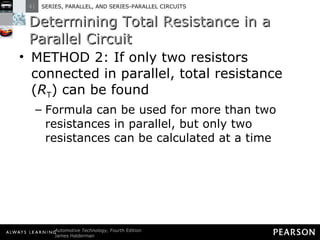
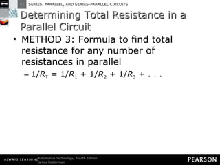
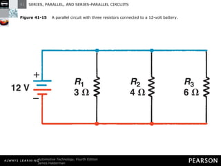
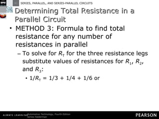
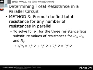
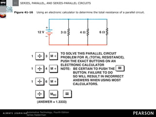
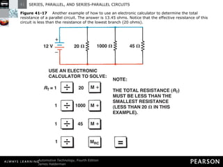
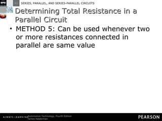
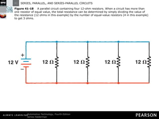
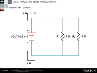
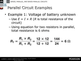
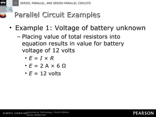
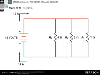
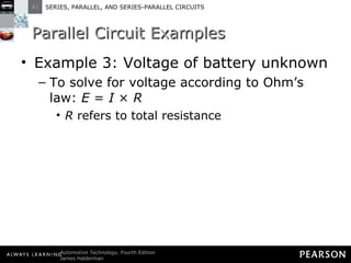
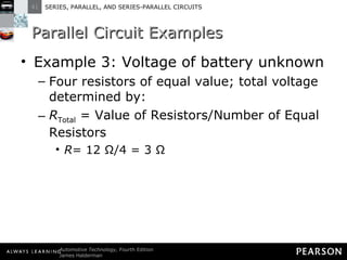
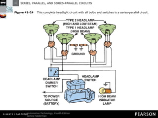
- Parallel circuits have multiple current paths and the same voltage across each branch, while current varies depending on resistance. Total resistance is less than the smallest individual resistance.


![Getting Started with Apache Spark: Big Data Made Simple [Free Meetup]](https://cdn.slidesharecdn.com/ss_thumbnails/apachesparkgettingstarted-260203175547-8361bcc3-thumbnail.jpg?width=640&height=640&fit=bounds)


