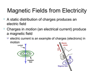
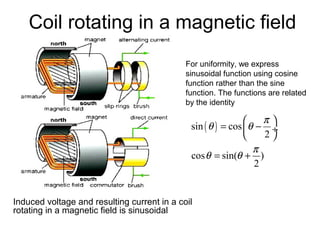
The magnetic field produced by an electric current has
direction, strength and geometry that depends on:
1. The direction of the current. The magnetic field circulates around the wire.
2. The amount of current. The stronger the current, the stronger the magnetic field.
3. The distance from the wire. The magnetic field strength decreases with distance from the wire.
So in summary, an electric current flowing through a wire produces a magnetic field that encircles the wire, with a strength that decreases with distance from the wire and depends on the amount of current. The direction of the magnetic field is given by the right-hand rule.
This document summarizes an active learning assignment on the emf equation of an alternator for a 4th semester electrical engineering student. It includes the introduction, equations for emf of an alternator, explanations of pitch factor and coil span factor, and references. The key points covered are the emf equation of an alternator as 4kfkckdfɸT volt, how the pitch factor measures the resultant emf of a short-pitched coil compared to a full pitched coil, and that the coil span factor is defined as the ratio of the voltage generated in a short pitch coil to a full pitch coil.
The document discusses energy band gaps in materials. It provides information on the density of electrons, energy gaps, and electric fields required for insulators, semiconductors, and metals. It then lists common materials used in semiconductors along with their band gap energies in electronvolts at 302 Kelvin. These include diamond, silicon dioxide, silicon, germanium, and lead sulfide. The document also discusses silicon-germanium alloys and intrinsic semiconductors. It covers doping, p-n junction diodes, their uses as electronic switches and rectifiers. Transistors are discussed for their uses as amplifiers, oscillators, and in integrated circuits. Radio broadcasting and reception is also mentioned
1. This document provides an overview of fundamental electrical engineering principles including: atom structure, charge, current, electromotive force, potential difference, resistance, Ohm's law, power, and series and parallel circuits.
2. Key concepts covered include that electrons carry charge and enable electrical current, while protons have a positive charge. Resistance opposes current flow. Ohm's law defines the relationship between voltage, current and resistance.
3. Examples are provided to demonstrate calculating current, voltage drops, power, and total resistance in series and parallel circuits using Ohm's law.
- AC circuits use alternating current that constantly changes in amplitude and direction. This allows the magnitude to be easily changed using transformers.
- The sine wave is the most common AC waveform, defined by amplitude, frequency, phase, and time. Peak, RMS, and average amplitudes are important measurements.
- Impedance combines resistance with reactance from inductors and capacitors. Reactance depends on frequency and causes current to lead or lag voltage in circuits.
this contant is physics related.Here AC current explain on the purpose of presentation with some equation and circuit diagram.i thaink it wiil be very effective for the students.
The document provides an introduction to electrical technology and the importance of electrical energy. It discusses how electricity has enabled economic development and improved living standards. Electrical energy is one of the most important forms of energy today because it is easy to control, cheap, clean, and flexible as it can be transmitted over long distances and converted to other forms. Electrical energy is generated by converting other sources of energy like chemical energy from fuels, nuclear energy, water pressure, wind, sunlight, and water into electrical energy using generators connected to these prime movers. The main sources of energy used today are fossil fuels like coal, oil and natural gas.
This document describes different types of instruments used for measurement of electrical quantities including permanent magnet moving coil instruments, moving iron instruments, electrodynamic instruments, hot-wire instruments, thermocouple instruments, induction-type instruments, electrostatic instruments, and rectifier-type instruments. It provides details on the working principles, advantages, disadvantages and applications of these instruments.
This document discusses fundamentals of electric circuits including basic concepts such as units of measurement, electric charge, current, voltage, power and energy. It describes circuit elements including passive elements like resistors, capacitors and inductors as well as active elements such as independent voltage and current sources and dependent sources. Independent sources provide a specified voltage or current regardless of the circuit, while dependent sources have an output that depends on another voltage or current in the circuit. The document also provides examples of calculating voltage using different source types.
This document provides an overview of bipolar junction transistors (BJTs). It discusses:
1. BJTs were invented in 1947 at Bell Labs and helped launch the technology revolution. They come in npn and pnp types.
2. BJTs have three doped semiconductor regions (emitter, base, collector) separated by two pn junctions. One type has an npn structure and the other a pnp structure.
3. BJTs are used as linear amplifiers to boost signals and as electronic switches. Proper biasing of the base-emitter and base-collector junctions is needed for transistor operation.
This document provides a summary of a seminar presentation on analyzing single phase AC circuits. The presentation covered various circuit elements in AC circuits including resistors, inductors, and capacitors in both series and parallel configurations. It discussed the concepts of impedance, phase relationships between voltage and current, and resonance. Resonance occurs when the inductive and capacitive reactances are equal, resulting in maximum current flow. The key topics were analyzing purely resistive, inductive, and capacitive circuits, and combinations using circuit laws and phasor diagrams.
This document provides an overview of basic electronics concepts including lattices, semiconductors, diodes, and transistors. It begins by defining lattices and their applications in mathematics. It then discusses superconductors, insulators, intrinsic and extrinsic semiconductors, and the band theory of conduction. Diodes and rectifiers are introduced, including half-wave and full-wave rectification circuits. The document concludes by explaining transistors, including bipolar junction transistors with npn and pnp configurations and their characteristics curves. Transistors are shown to have applications as amplifiers and switches in devices like LED spotlights and single transistor radios.
This document summarizes a seminar on energy bands and gaps in semiconductors. It discusses the introduction of energy bands, including valence bands, conduction bands, and forbidden gaps. It describes how materials are classified as insulators, conductors, or semiconductors based on their band gap energies. Direct and indirect band gap semiconductors are also defined. Intrinsic, n-type, and p-type semiconductors are classified based on their majority charge carriers.
Resistors are used in electric circuits to oppose electric current and are measured in ohms. They have two main characteristics - resistance value and power dissipation capacity. Resistors come in various resistance values and tolerances, and are used for purposes like heating and current limiting. They can be fixed or variable, and fixed resistors include carbon composition, metalized, and wire wound types. Variable resistors have three leads - two fixed and one movable - to allow adjustment of resistance while connected to a circuit.
An electric circuit is a closed loop that allows electric current to flow from a power source through various components like switches, fuses, and loads, and back to the source. The main parts of a circuit include an electrical source that delivers power, controlling devices that regulate the current, protection devices that prevent damage, conducting wires or paths, and loads that use the power. Circuits can be open or closed, and classified as series, parallel, or a combination depending on how the components are connected.
THIS PPT MAINLY DISCUSS ABOUT DOUBLE CAGE INDUCTION MOTOR AND IT'S CONSTRUCTION AND THIS PPT MAINLY CONTAINS THE DIFFERENT CHARACTERISTICS OF THE MACHINE IN VARIOUS FACTORS ANTHE PLOTTINGS ARE ALSO WE CAN SEE IN THIS PPT SO IT IS SO USEFUL TO ELECTRICAL MACHINES STUDENTS
Every person with an electronics background will be familiar with the three fundamental circuit elements - the resistor, the capacitor, and the inductor. These three elements are defined by the relation between two of the four fundamental circuit variables -
current, voltage, charge and flux.
In 1971, Leon Chua reasoned on the grounds of symmetry that there should be a fourth fundamental circuit element which gives the relationship between flux and charge. He named this circuit element the memristor, which is short for memory resistor. In May 2008, researchers at HP Labs published a paper announcing a model for the physical realization of the memristor.
It is proposed that memory storage devices that has very high data density and computers that require no time for boot up can be developed using memristor based hardware. A new physical quantity which is also introduced associated with memristor. It also solves someunexplained voltage current characteristics observed in certain materials at atomic levels.
This document discusses Tellegen's theorem of circuit theory. It states that at any time t, the algebraic sum of the instantaneous power in n branches of a network equals zero if Kirchhoff's current law (KCL) and Kirchhoff's voltage law (KVL) are satisfied. The document provides the mathematical statement of the theorem and proves it using a sample circuit where KCL and KVL are verified and the power in each branch is calculated to show that the total power supplied equals the total power dissipated.
Electrical properties of materialsElectrical properties of materialsElectrical properties of materialsElectrical properties of materialsElectrical properties of materialsElectrical properties of materialsElectrical properties of materialsElectrical properties of materialsElectrical properties of materialsElectrical properties of materialsElectrical properties of materialsElectrical properties of materialsElectrical properties of materialsElectrical properties of materialsElectrical properties of materialsElectrical properties of materialsElectrical properties of materialsElectrical properties of materialsElectrical properties of materialsElectrical properties of materialsElectrical properties of materialsElectrical properties of materialsElectrical properties of materialsElectrical properties of materialsElectrical properties of materialsElectrical properties of materialsElectrical properties of materialsElectrical properties of materialsElectrical properties of materialsElectrical properties of materialsElectrical properties of materialsElectrical properties of materialsElectrical properties of materialsElectrical properties of materialsElectrical properties of materialsElectrical properties of materials
This document provides an overview of capacitors including: what a capacitor is, how it is measured, how to connect capacitors in series and parallel circuits, and how to make a simple capacitor. It discusses that a capacitor consists of two plates separated by an insulator and stores electrical energy. The document outlines that it will cover the capacitor unit, reasons for its use, connection configurations, equivalent circuits, formulas, examples, charging and discharging curves, and materials needed to make a basic capacitor. Contact information is provided for any questions.
This document discusses the history and characteristics of alternating current (AC). It explains that AC electricity is generated by an AC electric generator and flows first in one direction and then the other, unlike direct current. Some key advantages of AC are that it can be transformed between voltages and controlled by various circuit components. The document also covers concepts such as reactance, impedance, and phase relationships in AC circuits. It describes how AC behaves differently than DC in capacitors and inductors due to the changing current.
Capacitors are electronic components that store electric charge between two conductive plates separated by an insulating material called a dielectric. The capacitance of a capacitor depends on the surface area and distance between the plates, as well as the dielectric material. Common types of capacitors include electrolytic, ceramic, mica, paper, and film capacitors. Multilayer ceramic capacitors (MLCCs) contain many thin layers that increase their capacitance while maintaining a small size, making them well-suited for applications requiring small capacitances. Capacitors are used widely in electronic devices to filter signals and store energy.
The document discusses various electrical and electronic components. It defines voltage, current, and resistance, and explains Ohm's law. It describes different types of resistors, including variable resistors, and how resistors can be connected in series or parallel. It also discusses semiconductor components like diodes, LEDs, transistors, capacitors, and relays. It provides examples of simple circuits using these components.
The document discusses active and passive components in electronics. It defines passive components as circuit elements that receive and store energy in electric or magnetic fields, but cannot continuously deliver power. Passive components mentioned include capacitors, inductors, and transformers. Active components are defined as having gain or ability to control voltage/current, and include transistors and integrated circuits. The document provides examples of capacitors, inductors, and transformers as passive elements, and contrasts them with transistors as active elements.
This document discusses different types of diodes, including their basic functions and applications. It begins with an overview of basic diodes and their current-voltage characteristics. It then focuses on special diodes like Zener diodes, which maintain a relatively constant voltage when operated in reverse breakdown. Other diodes discussed include varactor diodes, light-emitting diodes (LEDs), photodiodes, Schottky diodes, laser diodes, PIN diodes, current regulator diodes, step-recovery diodes, and tunnel diodes. Each type has a specialized function and is commonly used in applications like power regulation, displays, optical communications, and high-frequency switching.
This document provides an overview of key electronics concepts and components. It discusses basic concepts like capacitors, inductors, and measurements tools. It also covers topics such as types of circuits, Kirchhoff's laws, Ohm's law, resistors, and power sources. The document aims to introduce fundamental electronics principles and components.
The document defines linear and nonlinear elements, active and passive elements, and unilateral and bilateral elements in electric circuits. It introduces Ohm's law, which states that current is directly proportional to voltage and inversely proportional to resistance. Kirchhoff's laws are also summarized: Kirchhoff's current law states that the algebraic sum of currents at a node is zero, and Kirchhoff's voltage law states that the algebraic sum of voltages in a closed loop is zero. An example circuit is also solved using these laws and Ohm's law to find currents and voltages.
1. The document discusses basic circuit laws including Ohm's Law, Kirchhoff's Laws, and how resistors behave in series and parallel configurations.
2. Georg Ohm published his law relating voltage and current through a resistor in 1827. Kirchhoff developed his laws for calculating voltages and currents in circuits in 1845.
3. Kirchhoff's Current Law states that the algebraic sum of currents entering and leaving a node is zero. Kirchhoff's Voltage Law states that the algebraic sum of voltages around any closed loop is zero.
The document contains 7 questions related to electrical circuits and concepts. The questions cover topics like calculating current given charge and time, determining energy given power and current, calculating heat dissipation in a resistor, determining motor supply current given other parameters, calculating energy cost for running a train, identifying resistor values based on color bands, and calculating lamp supply current and power for parallel circuits.
This document provides an overview of basic circuit laws including Ohm's law, Kirchhoff's laws, and analysis of series and parallel circuits. Ohm's law states that voltage across a resistor is proportional to current through the resistor. Kirchhoff's laws include the junction rule that the total current entering a node equals the total leaving, and the loop rule that the sum of all potential differences around a closed loop is zero. Series and parallel circuits are analyzed using concepts like equivalent resistance, voltage division, and current division. Examples are provided to demonstrate applying these circuit analysis techniques.
This document provides an introduction to electricity, including its behavior at the atomic level. It discusses how electricity is created through the movement of electrons between atoms. At the atomic level, atoms are made up of protons, neutrons, and electrons. The number of protons determines the element. Electricity flows as electrons move between unfilled valence orbits of atoms. Conductors have atoms with unfilled orbits that allow electron flow, while insulators have filled orbits preventing flow. Ohm's law defines the relationship between voltage, current, and resistance in circuits. Circuits can be connected in series or parallel, and Kirchhoff's laws apply to each. Power is the product of current and voltage and measured in watts.
The document provides an introduction to electricity, including its behavior at the atomic level. It describes how electricity is created through the movement of electrons between atoms. It also explains key concepts in electrical circuits such as voltage, current, resistance, and Ohm's law. Circuit configurations such as series and parallel are defined, and equations like Kirchhoff's laws are presented for analyzing circuits.
This document provides an introduction to electricity, including:
1) It explains electricity at the atomic level, describing atoms, protons, neutrons, electrons, and electron orbitals.
2) It introduces concepts of conductors and insulators, explaining that conductors have 1-3 valence electrons allowing electron flow between atoms, while insulators have 5-8 valence electrons making flow difficult.
3) It describes the basics of electrical circuits, including current, voltage, resistance, and Ohm's Law, and how to measure these properties with a multimeter. Kirchhoff's Laws for series and parallel circuits are also introduced.
The document provides an introduction to electricity, including its behavior at the atomic level. It describes how electricity is created through the movement of electrons between atoms. It also explains key concepts in electrical circuits such as voltage, current, resistance, and Ohm's law. Circuit configurations such as series and parallel are defined, and equations like Kirchhoff's laws are presented for analyzing circuits.
This document outlines the key concepts and learning outcomes for a circuit theory course, including:
1) Explaining DC circuits using concepts like EMF, internal resistance, and potential dividers.
2) Analyzing DC circuits using Kirchhoff's laws to solve problems involving resistors, capacitors, and energy stored.
3) Describing resistance at a microscopic level and defining related concepts like resistivity and conductance.
This document outlines the key concepts and learning outcomes for a circuit theory course, including:
1) Explaining DC circuits using concepts such as EMF, internal resistance, and potential dividers.
2) Analyzing DC circuits using Kirchhoff's laws to solve problems involving resistors, capacitors, and energy stored.
3) Describing resistance at a microscopic level and defining related concepts like resistivity and conductance.
This document outlines the key concepts and learning outcomes for a circuit theory course, including:
1) Explaining DC circuits using concepts like EMF, internal resistance, and potential dividers.
2) Analyzing DC circuits using Kirchhoff's laws to solve problems involving resistors, capacitors, and energy stored.
3) Describing resistance at a microscopic level and defining related concepts like resistivity and conductance.
This document outlines the key concepts and learning outcomes for a circuit theory course, including:
1) Explaining DC circuits using concepts like EMF, internal resistance, and potential dividers.
2) Analyzing DC circuits using Kirchhoff's laws to solve problems involving resistors, capacitors, and energy stored.
3) Giving a microscopic description of resistance in wires using concepts like resistivity and conductivity.
4) Covering related practical work using equipment like voltmeters and capacitors.
- The natural response of a circuit refers to the behavior of the circuit when external sources are removed. This allows the stored energy in inductors and capacitors to dissipate.
- The general solution for the natural response of RL and RC circuits is an exponential decay from an initial value to a final value, with the decay rate determined by the circuit time constant.
- For an RL circuit, the inductor current decays exponentially with time constant L/R. For an RC circuit, the capacitor voltage decays exponentially with time constant RC.
A capacitor in an AC circuit leads the voltage by 90 degrees. As frequency increases, capacitive reactance decreases and maximum current increases. For a 2-μF capacitor connected to a 120-V, 60-Hz source, the effective current is 90.5 mA and peak current is 128 mA.
1) The document covers circuit theory topics including circuit topology, voltage, current and power, Kirchoff's laws, active and passive circuit components, and DC and AC circuits.
2) It defines basic circuit concepts such as voltage, current, impedance, and uses Kirchoff's laws and Laplace transforms to analyze circuits.
3) Examples are provided to illustrate circuit analysis techniques for DC circuits using Ohm's law and AC circuits using impedance.
The document provides an overview of key topics in alternating current (AC) circuits covered in Chapter 31, including:
1) The use of phasors to describe sinusoidally varying quantities in AC circuits such as resistors, inductors, and capacitors.
2) Analyzing RLC series circuits driven by a sinusoidal voltage source using phasors.
3) Factors that determine the power in an AC circuit such as the current and voltage amplitudes and their phase relationship.
4) Resonance in RLC circuits and the effect of frequency on current.
5) Transformers and how they can change AC voltages and currents through electromagnetic induction.
1) The document discusses DC fundamentals and circuits, covering topics like charge, current, voltage, power, energy, Ohm's law, and Kirchhoff's laws. It also covers basic circuit analysis using these principles.
2) Key concepts discussed include the definitions of current, voltage, resistance, and time constants. Kirchhoff's laws and Ohm's law are also summarized.
3) Examples are provided to demonstrate using these principles to solve circuits for unknown currents and voltages. Circuit analysis techniques like mesh current analysis and nodal voltage analysis are also mentioned.
Here are the steps to solve this example:
1) Find the moment of inertia, I, of the composite section about the neutral axis:
I = I1 + I2 + A1*d1^2 + A2*d2^2
Where:
I1 = moment of inertia of rectangular section 1 = b1*h1^3/12 = 4*6^3/12 = 144 in^4
I2 = moment of inertia of rectangular section 2 = b2*h2^3/12 = 2*4^3/12 = 32 in^4
A1 = area of section 1 = b1*h1 = 4*6 = 24 in^2
A
This document summarizes key concepts related to static engineering systems including:
- Types of columns that can fail in true compression (short columns) or buckle before reaching full strength (long columns).
- Types of beams classified by their support conditions.
- Loads that can be applied to beams as concentrated loads or uniformly distributed loads.
- Shear forces and bending moments that develop in beams due to applied loads, and sign conventions for positive and negative shear forces and moments.
- Relationships for calculating shear forces and bending moments along beams subjected to different load types.
- Examples of determining shear forces and bending moments at points along cantilever beams and beams with various concentrated and uniform loads
1) Uniform acceleration, energy transfer, and oscillating mechanical systems are examined in Chapter 2 on dynamic engineering systems.
2) Outcomes for Chapter 2 include analyzing dynamic systems involving uniform acceleration and determining the behavior of oscillating mechanical systems.
3) Mechanics involves the study of kinematics (motion), kinetics (forces), and statics (equilibrium) to describe the behavior of objects.
This document summarizes key concepts about transformers:
1) Transformers transfer electrical energy from one voltage level to another through magnetic coupling between primary and secondary coils. They do not directly convert electrical to mechanical energy.
2) An ideal transformer transfers power without losses, but real transformers have resistive losses in their coils and core that reduce efficiency.
3) The voltage and current ratios between primary and secondary coils are determined by their relative turn ratios; this relationship allows impedances to be transferred between sides.
This document discusses static engineering systems and structural members experiencing bending. It covers key concepts such as:
- The bending of structural members and the neutral axis where the length remains unchanged during bending.
- How bending stress varies across a beam's cross-section, with maximum stress occurring on the surfaces furthest from the neutral axis.
- The general bending formula that relates bending moment, stress, elastic modulus, and distance from the neutral axis.
- Other bending concepts like the second moment of area, parallel axis theorem, and position of the neutral axis through the centroid.
Worked examples demonstrate calculating bending stresses, moments, strains, and selecting suitable beam dimensions.
The document describes information and energy control systems. It discusses block diagrams of typical information systems like audio and process monitoring systems. It explains how electrical signals convey system information and the functions of system components like transducers, amplifiers, oscillators, analog to digital converters and digital to analog converters. It also discusses the effects of noise on systems and how system output is determined from a given input.
This document summarizes key concepts about transformers:
1) Transformers transfer electrical energy from one voltage level to another through a magnetic field without changing frequency. They have a primary and secondary winding wound around an iron core.
2) An AC voltage applied to the primary induces a voltage in the secondary according to Faraday's Law of induction. The ratio of voltages is determined by the ratio of turns in the windings.
3) Real transformers have losses that are modeled in an equivalent circuit including resistances of the windings and core and a magnetizing reactance. Impedances can be transferred between windings using the turns ratio.
This document discusses DC and AC theory, including:
1) Key DC electrical principles such as Ohm's and Kirchhoff's laws, voltage and current dividers, and fundamental relationships involving resistance, inductance, capacitance.
2) Definitions of electrical current, voltage, resistors, and an introduction to Ohm's law.
3) The differences between direct current (DC) and alternating current (AC) and examples of their waveforms. Kirchhoff's laws and their use in circuit analysis are also covered.
The document discusses torsion in circular shafts. It covers the assumptions in torsion theory including the determination of shear stress, strain, and modulus. It also describes the distribution of shear stress and angle of twist in solid and hollow circular shafts. Key points include:
- Shear stress is highest at the surface and decreases linearly towards the center of a shaft.
- Angle of twist is proportional to both the applied torque and length of the shaft.
- Cross sections remain plane during twisting for circular shafts but may become distorted for non-circular shafts.
This document discusses the selection and design of standard steel beams and columns. It provides information on:
1) How to select standard steel sections from reference tables that list section properties like elastic section modulus.
2) How to calculate required section modulus based on maximum bending moment and allowable stress.
3) Guidelines for selecting sections, including choosing sections that minimize weight for beams and have slenderness ratios below 180 for columns.
4) An example of designing a simply supported beam by calculating bending moment, allowable stress, and required section modulus.
The document discusses the design of ventilation, air conditioning, and other building systems. It outlines the purpose of ventilation systems to provide occupant comfort while saving energy. Important factors to consider for ventilation design include the local climate, building air tightness, and pressure balances. When selecting an air conditioning system, factors like room size, windows, occupants, and heat sources must be evaluated. Fire protection requirements include posting the fire safety plan at entrances and distributing copies to tenants.
Here are the solutions to the simple harmonic motion problems:
1. Amplitude = 20 cm
Frequency = 31.4 rad/s
Period = 2π/31.4 = 0.2 s
2. Maximum displacement = 50 cm
Maximum velocity = 1000 cm/s (20π rad/s)
Maximum acceleration = 40000 cm/s^2 (400π^2 rad^2/s^2)
Number of oscillations in 5 s = 5 * 20π = 100
3. Displacement x(t) = 20 cos(2πt/0.5) cm
Velocity v(t) = -40π sin(2πt/0.5) cm
This chapter discusses dynamic engineering systems including uniform acceleration, energy transfer through various forms like potential and kinetic energy, and oscillating mechanical systems. It covers concepts like Newton's laws of motion, conservation of energy, and how energy is transferred and stored in linear and rotating systems, as well as damped oscillatory motion. Simple harmonic motion of linear and transverse systems is also qualitatively examined.
This document discusses static engineering systems and specifically simply supported beams. It covers topics such as determination of shear force, bending moment, stress due to bending, eccentric loading of columns, stress distribution, and the middle third rule. It also defines short and long columns, different types of beam supports, and how loads can be applied to beams as concentrated or distributed loads. The document discusses shear forces and bending moments created by loads on beams and provides conventions for defining positive and negative shear forces and bending moments. It also provides relationships and diagrams for shear forces and bending moments under different load conditions including concentrated loads, uniform loads, and multiple concentrated loads. An example problem is also included.
Here are the key points about momentum and impulse:
- Momentum is the product of an object's mass and velocity. It represents the amount of motion an object has.
- Impulse is the product of force and the time over which it acts. It represents the change in an object's momentum due to a force.
- Impulse and change in momentum are directly related - a large impulse (large force or long duration) results in a large change in momentum.
- Both momentum and impulse are vector quantities, having both magnitude and direction associated with the motion or force.
So in summary, momentum describes the amount of motion, while impulse describes the force applied to change an object's motion and momentum.
Here are the steps to solve this example:
1) Find the moment of inertia, I, of the composite section about the neutral axis:
I = I1 + I2 + A1*d1^2 + A2*d2^2
Where:
I1 = moment of inertia of rectangular section 1 = b1*h1^3/12 = 4*6^3/12 = 144 in^4
I2 = moment of inertia of rectangular section 2 = b2*h2^3/12 = 2*4^3/12 = 32 in^4
A1 = area of section 1 = b1*h1 = 4*6 = 24 in^2
A
Main Java[All of the Base Concepts}.docxadhitya5119
This is part 1 of my Java Learning Journey. This Contains Custom methods, classes, constructors, packages, multithreading , try- catch block, finally block and more.
Gender and Mental Health - Counselling and Family Therapy Applications and In...PsychoTech Services
A proprietary approach developed by bringing together the best of learning theories from Psychology, design principles from the world of visualization, and pedagogical methods from over a decade of training experience, that enables you to: Learn better, faster!
Philippine Edukasyong Pantahanan at Pangkabuhayan (EPP) CurriculumMJDuyan
(𝐓𝐋𝐄 𝟏𝟎𝟎) (𝐋𝐞𝐬𝐬𝐨𝐧 𝟏)-𝐏𝐫𝐞𝐥𝐢𝐦𝐬
𝐃𝐢𝐬𝐜𝐮𝐬𝐬 𝐭𝐡𝐞 𝐄𝐏𝐏 𝐂𝐮𝐫𝐫𝐢𝐜𝐮𝐥𝐮𝐦 𝐢𝐧 𝐭𝐡𝐞 𝐏𝐡𝐢𝐥𝐢𝐩𝐩𝐢𝐧𝐞𝐬:
- Understand the goals and objectives of the Edukasyong Pantahanan at Pangkabuhayan (EPP) curriculum, recognizing its importance in fostering practical life skills and values among students. Students will also be able to identify the key components and subjects covered, such as agriculture, home economics, industrial arts, and information and communication technology.
𝐄𝐱𝐩𝐥𝐚𝐢𝐧 𝐭𝐡𝐞 𝐍𝐚𝐭𝐮𝐫𝐞 𝐚𝐧𝐝 𝐒𝐜𝐨𝐩𝐞 𝐨𝐟 𝐚𝐧 𝐄𝐧𝐭𝐫𝐞𝐩𝐫𝐞𝐧𝐞𝐮𝐫:
-Define entrepreneurship, distinguishing it from general business activities by emphasizing its focus on innovation, risk-taking, and value creation. Students will describe the characteristics and traits of successful entrepreneurs, including their roles and responsibilities, and discuss the broader economic and social impacts of entrepreneurial activities on both local and global scales.
ISO/IEC 27001, ISO/IEC 42001, and GDPR: Best Practices for Implementation and...PECB
Denis is a dynamic and results-driven Chief Information Officer (CIO) with a distinguished career spanning information systems analysis and technical project management. With a proven track record of spearheading the design and delivery of cutting-edge Information Management solutions, he has consistently elevated business operations, streamlined reporting functions, and maximized process efficiency.
Certified as an ISO/IEC 27001: Information Security Management Systems (ISMS) Lead Implementer, Data Protection Officer, and Cyber Risks Analyst, Denis brings a heightened focus on data security, privacy, and cyber resilience to every endeavor.
His expertise extends across a diverse spectrum of reporting, database, and web development applications, underpinned by an exceptional grasp of data storage and virtualization technologies. His proficiency in application testing, database administration, and data cleansing ensures seamless execution of complex projects.
What sets Denis apart is his comprehensive understanding of Business and Systems Analysis technologies, honed through involvement in all phases of the Software Development Lifecycle (SDLC). From meticulous requirements gathering to precise analysis, innovative design, rigorous development, thorough testing, and successful implementation, he has consistently delivered exceptional results.
Throughout his career, he has taken on multifaceted roles, from leading technical project management teams to owning solutions that drive operational excellence. His conscientious and proactive approach is unwavering, whether he is working independently or collaboratively within a team. His ability to connect with colleagues on a personal level underscores his commitment to fostering a harmonious and productive workplace environment.
Date: May 29, 2024
Tags: Information Security, ISO/IEC 27001, ISO/IEC 42001, Artificial Intelligence, GDPR
-------------------------------------------------------------------------------
Find out more about ISO training and certification services
Training: ISO/IEC 27001 Information Security Management System - EN | PECB
ISO/IEC 42001 Artificial Intelligence Management System - EN | PECB
General Data Protection Regulation (GDPR) - Training Courses - EN | PECB
Webinars: https://pecb.com/webinars
Article: https://pecb.com/article
-------------------------------------------------------------------------------
For more information about PECB:
Website: https://pecb.com/
LinkedIn: https://www.linkedin.com/company/pecb/
Facebook: https://www.facebook.com/PECBInternational/
Slideshare: http://www.slideshare.net/PECBCERTIFICATION
Temple of Asclepius in Thrace. Excavation resultsKrassimira Luka
The temple and the sanctuary around were dedicated to Asklepios Zmidrenus. This name has been known since 1875 when an inscription dedicated to him was discovered in Rome. The inscription is dated in 227 AD and was left by soldiers originating from the city of Philippopolis (modern Plovdiv).
This document provides an overview of wound healing, its functions, stages, mechanisms, factors affecting it, and complications.
A wound is a break in the integrity of the skin or tissues, which may be associated with disruption of the structure and function.
Healing is the body’s response to injury in an attempt to restore normal structure and functions.
Healing can occur in two ways: Regeneration and Repair
There are 4 phases of wound healing: hemostasis, inflammation, proliferation, and remodeling. This document also describes the mechanism of wound healing. Factors that affect healing include infection, uncontrolled diabetes, poor nutrition, age, anemia, the presence of foreign bodies, etc.
Complications of wound healing like infection, hyperpigmentation of scar, contractures, and keloid formation.
Chapter wise All Notes of First year Basic Civil Engineering.pptxDenish Jangid
Chapter wise All Notes of First year Basic Civil Engineering
Syllabus
Chapter-1
Introduction to objective, scope and outcome the subject
Chapter 2
Introduction: Scope and Specialization of Civil Engineering, Role of civil Engineer in Society, Impact of infrastructural development on economy of country.
Chapter 3
Surveying: Object Principles & Types of Surveying; Site Plans, Plans & Maps; Scales & Unit of different Measurements.
Linear Measurements: Instruments used. Linear Measurement by Tape, Ranging out Survey Lines and overcoming Obstructions; Measurements on sloping ground; Tape corrections, conventional symbols. Angular Measurements: Instruments used; Introduction to Compass Surveying, Bearings and Longitude & Latitude of a Line, Introduction to total station.
Levelling: Instrument used Object of levelling, Methods of levelling in brief, and Contour maps.
Chapter 4
Buildings: Selection of site for Buildings, Layout of Building Plan, Types of buildings, Plinth area, carpet area, floor space index, Introduction to building byelaws, concept of sun light & ventilation. Components of Buildings & their functions, Basic concept of R.C.C., Introduction to types of foundation
Chapter 5
Transportation: Introduction to Transportation Engineering; Traffic and Road Safety: Types and Characteristics of Various Modes of Transportation; Various Road Traffic Signs, Causes of Accidents and Road Safety Measures.
Chapter 6
Environmental Engineering: Environmental Pollution, Environmental Acts and Regulations, Functional Concepts of Ecology, Basics of Species, Biodiversity, Ecosystem, Hydrological Cycle; Chemical Cycles: Carbon, Nitrogen & Phosphorus; Energy Flow in Ecosystems.
Water Pollution: Water Quality standards, Introduction to Treatment & Disposal of Waste Water. Reuse and Saving of Water, Rain Water Harvesting. Solid Waste Management: Classification of Solid Waste, Collection, Transportation and Disposal of Solid. Recycling of Solid Waste: Energy Recovery, Sanitary Landfill, On-Site Sanitation. Air & Noise Pollution: Primary and Secondary air pollutants, Harmful effects of Air Pollution, Control of Air Pollution. . Noise Pollution Harmful Effects of noise pollution, control of noise pollution, Global warming & Climate Change, Ozone depletion, Greenhouse effect
Text Books:
1. Palancharmy, Basic Civil Engineering, McGraw Hill publishers.
2. Satheesh Gopi, Basic Civil Engineering, Pearson Publishers.
3. Ketki Rangwala Dalal, Essentials of Civil Engineering, Charotar Publishing House.
4. BCP, Surveying volume 1
How to Make a Field Mandatory in Odoo 17Celine George
In Odoo, making a field required can be done through both Python code and XML views. When you set the required attribute to True in Python code, it makes the field required across all views where it's used. Conversely, when you set the required attribute in XML views, it makes the field required only in the context of that particular view.
हिंदी वर्णमाला पीपीटी, hindi alphabet PPT presentation, hindi varnamala PPT, Hindi Varnamala pdf, हिंदी स्वर, हिंदी व्यंजन, sikhiye hindi varnmala, dr. mulla adam ali, hindi language and literature, hindi alphabet with drawing, hindi alphabet pdf, hindi varnamala for childrens, hindi language, hindi varnamala practice for kids, https://www.drmullaadamali.com
Communicating effectively and consistently with students can help them feel at ease during their learning experience and provide the instructor with a communication trail to track the course's progress. This workshop will take you through constructing an engaging course container to facilitate effective communication.
1. Chapter 3- DC and AC theory
3.1 DC electrical principles
3.1.1 Ohm’s and Kirchhoff’s laws
3.1.2 voltage and current dividers
3.1.3 analogue and digital signals
3.1.4 review of motor and generator principles
3.1.5 fundamental relationships (eg resistance,
inductance, capacitance; series C-R circuit, time
constant, charge and discharge curves of
capacitors, L-R circuits)
2. Electrical current
Electrical current is the rate of flow of
electrical charge through a conductor or
circuit element.
The units are amperes (A), which are
equivalent to coulombs per second (C/s).
4. Direction of current
The current direction in the circuit elements
(a) Indicating current i1 flows from
a to b
(b) Indicating current i2 flows from
b to a
5. Voltage
The voltage associated with a circuit
element is the energy transferred per unit
of charge that flows through the element.
The units of voltage are Volts (V), which are
equivalent to joules per coulomb (J/C).
Note:
Relationship between voltage and current is
given by ohms law
6. Direction of voltage drop
The voltage vab has a
reference polarity that is
positive at point a and
negative at point b
The positive reference for
v is at the head of the
arrow.
7. Resistor
• A resistor is a circuit element that dissipates
electrical energy (usually as heat)
• Eg: incandescent light bulbs, heating elements
(stoves, heaters, etc.), long wires
• It may be lumped (eg: bulbs) or continuous type
(distribution lines)
• Resistance is measured in Ohms (Ω)
• Demonstration of colour code calculator
8. Resistance Related to Physical Parameters
ρL
R=
A
ρ is the resistivity of the material used to construct
the resistor (Unit is Ohm-meter)
9.
10.
11.
12. Resistor construction
Old style carbon resistor: Ceramic cylinder with thin
film layer that is made converted into a special carbon
wire by cutting groves in the cylinder
New style carbon resistor: Ceramic plate with carbon
film layer that is converted into long zig-zag wire with
groves
13. Questions to think
• Why carbon is used for resistors
• Why did they change in shape
• Why use resistors
• How the power rating of the resistor get
changes
• What is the standard symbol of a resistor
• What is a conductor
14. Ohms law
• Ohms law: Current through a resistor is
proportional to the voltage applied across it at a
given temperature
• Ohms law establishes a relationship between
voltage and current. It can be mathematically
expressed as
I ∝V
1 V- Voltage
I = V
R I – Current
V = IR R - Resistance
16. Power and energy
p(t ) = v (t )i (t )
P - Power (J/s or W)
t2
w = ∫ p(t )dt W - energy (J)
t1
p(t) = v(t)i(t)
From ohms law v(t) = i(t)R or i(t) = v(t)/R
p(t) = i2(t) R = v2(t)/R
17. Example: a 25W Bulb
• If the voltage across a 25W bulb is 120V,
what is its resistance?
R = V2/P = (120V)2/25W = 576 Ω
• What is the current flowing through the
25W bulb?
I = V/R = 120V/576 Ω = 0.208 A
18. Thought Question
• When measured the resistance of a 25W
bulb, the value got was about 40Ω.
What’s wrong here?
• Answer: The resistance of a wire
increases as the temperature increases.
For tungsten, the temperature coefficient
of resistivity is 4.5x10⁻³/oK. A light bulb
operates at about 5000oF.
19. Direct Current (DC) and
Alternating Current (AC)
When a current is constant with time, we say
that we have direct current, abbreviated as dc.
On the other hand, a current that varies with
time, reversing direction periodically, is called
alternating current, abbreviated as ac.
24. Kirchoff’s law
• KIRCHHOFF’S CURRENT LAW (KCL)
The net current entering a node is zero.
Alternatively, the sum of the currents entering a
node equals the sum of the currents leaving a
node.
• KIRCHHOFF’S VOLTAGE LAW (KVL)
The algebraic sum of the voltages equals zero
for any closed path (loop) in an electrical circuit
25. KCL (Kirchhoff’s Current Law)
i1(t) i5(t)
i2(t) i4(t)
i3(t)
The sum of currents entering the node is
n zero:
∑ i (t ) = 0
j =1
j
Analogy: mass flow at pipe junction
26. KVL (Kirchhoff’s Voltage Law)
+ –
v2(t) +
+
v1(t) v3(t)
–
–
• The sum of voltages around a loop is
zero: n
∑ v j (t ) = 0
j =1
• Analogy: pressure drop thru pipe loop
27. KVL Polarity
• A loop is any closed path through a circuit
in which no node is encountered more
than once
• Voltage Polarity Convention
– A voltage encountered + to - is positive
– A voltage encountered - to + is negative
28. In applying KVL to a
loop, voltages are added
or subtracted depending
on their reference
polarities relative to the
direction of travel
around the loop
33. Voltage Dividers
• Resistors in series
provide a mechanism
• The resistors
determine the output
Voltage
• KCL says same
current in R1 and R2
• Vout =
Example: Light dimmer (has a potentiometer
V1 * R2/(R1+R2) which is a variable resistance). You dim the
light by the ratio of resistors dropping the
voltage going to the light bulb
35. Voltage Division
R1
v1 = R1i = v total
R1 + R2 + R3
R2
v 2 = R2 i = v total
R1 + R2 + R3
R3
v3 = R3i = vtotal
R1 + R2 + R3
36. Current Dividers
• Resistors in parallel provide a mechanism
• The resistors determine the current in
each path
• I1 * R1 = I2 * R2, I2 = I1 * R1/R2
• I = I1 + I2 I1 = I * R2/(R1+R2)
I1
R1
I
I2 R2
38. Current Division
v R2
i1 = = itotal
R1 R1 + R2
v R1
i2 = = itotal
R2 R1 + R2
39. Example Dividers
• Given 10V, Need to
provide 3V, how?
• Resistors in Series
• R2/(R1+R2) = 3/10, choose
R2 = 300 KΩ
• R1 = 700 KΩ
• Why should R1, R2 be
high?
• What happens when we
connect a resistor R3
across R2?
40. Example Dividers
• Want to divide current into two paths, one
with 30% --how?
• Resistors in parallel
• R2/(R1+R2) = 0.3, Choose R2 = 300 KΩ
• R1 = 700 KΩ
• Why should R1, R2 be high?
• What happens when we connect a resistor
R3 in series with R2?
41. • Although the following concepts are
very important they are not sufficient
to solve all circuits
– series/parallel equivalents
– current/voltage division
principles
42. Signal and waveform
• A signal is a physical quantity, or quality, which
conveys information
• The variation of the signal value as a function of
the independent variable is called a waveform
• The independent variable often represents time
• We define a signal as a function of one
independent variable that contains information
about the behavior or nature of a phenomenon
• We assume that the independent variable is
time even in cases where the independent
variable is a physical quantity other than time
43. Continuous or analog signals
• Continuous signal is a signal that exists
at every instant of time
• In the jargon of the trade, a continuous
signal is often referred to as
continuous time or analog
• The independent variable is a
continuous variable
• Continuous signal can assume any value
over a continuous range of numbers
44. Discrete-time signals
• A signal defined only for discrete values of
time is called a discrete-time signal or
simply a discrete signal
• Discrete signal can be obtained by taking
samples of an analog signal at discrete
instants of time
• Digital signal is a discrete-time signal
whose values are represented by digits
45. What is sampling?
• Sampling is capturing a signal at an
instant in time
• Sampling means taking amplitude values
of the signal at certain time instances
• Uniform sampling is sampling every T
units of time
xk = x(kT ) = x(t ) t =0,±T ,±2T ,±3T ,
Sampling
frequency or 1
sampling rate F0 = time step or
T sample interval
46. Sinusoidal signal
x s (t ) = X s sin( 2πf s t + φ s )
Amplitude Phase in
radian (rad)
xx(t) ==X ssin(2 ππf f st t++φφ) )
s
(t) X sin(2
s
2 s s s s
2
Time in
seconds (s)
0
s
xx
0
s
Frequency in
Hertz (Hz)
-2
-2-0.1 0 0.1 0.2
-0.1 0 0.1 0.2
tt
47. Modern Capacitors
Ceramic and Electrolyte Capacitors
High Voltage Capacitor Banks
48. Capacitor
• Capacitors consist of two conductors( insulated from each other) which carry
equal and opposite charges +q and –q.
• If the capacitor is charged then there is a potential difference V between the
two conductors
• The material between the plates is insulating. It has no free charge; charge
does not pass through the insulator to move from one plate to another.
• The charge q is proportional to the potential difference V
• q =CV
• The proportionality constant C is called the capacitance of the capacitor. Its
value depends on the geometry of the plates and not the charge or potential
difference. The unit of capacitance is FARAD
49. Factors Affecting Capacitance
Area – directly proportional to
plate area, ‘A’
Spacing – inversely proportional
to plate spacing, ‘d’
Dielectric-dependent on the
dielectric as
A
C = ε ( Farad )
d
ε = permittivity of dielectric ( F / m )
50. Capacitors in Parallel
But V1=V2=V
Total charge ie. Q = Q1+Q2
= C1V+C2V = V(C1+C2)
=VCeq
Where Ceq=C1+C2
51. Capacitors in Series
V1+V2=V, Q/C1+ Q/C2 =V
Q(1/C1 + 1/C2) =V, i.e. 1/Ceq = 1/C1 +1/C2
Therefore Ceq = (C1C2)/ (C1+C2)
52. Voltage-Current Relationship
q(t ) = CVc (t )
dq (t ) dVc (t )
ic (t ) = =C
dt dt
dVc (t )
∴ ic (t ) = C
dt
t
1
Vc (t ) = ∫ ic (t )dt + Vc (t0 )
C t0
53. Energy Stored in a Capacitor
t
w(t ) = ∫ v(t )i (t ) dt
to
t
dv
= ∫ v C dt
to
dt
cancelling differential time and changing
the limits to the corresponding
voltages, we have
v(t ) 1 2 1 q 2 (t )
=∫ Cv dv = Cv (t ) = v(t )q (t ) =
0 2 2 2C
54. CAPACITORS – DC
Stores charge: Q (Coulombs) I =∆Q/∆T
Flow of charge is Current: I (Amperes)
I
dVC
I =C
dt
1
VC = ∫ idt
C
The capacitor charges
linearly till the voltage across
it reaches the applied
voltage after which the
driving force is lost and the
capacitor ‘blocks’ DC.
Example: Time delay circuit
55. RC CIRCUIT – DC
VC (t ) = V (1 − e −t / RC )
- VC +
- VR + This is similar but the
capacitor charges non-linearly
till the voltage across it
reaches the applied voltage
after which the driving force is
lost. Time constant τ=RC is
τ the time in which the
capacitor is charged to 67%
56. RC CIRCUIT – DC
Vo
After a capacitor has charged to
- VC(t) +
I V0, it discharges if there is a
resistance in the external circuit
(otherwise it retains the charge :
Vo use in DRAMs). The discharge is
non-linear VC (t ) = V0 e − t / RC
Time constant
= RC
Example: Discharge the defibrillator
capacitor into the heart
• We will return to Capacitors in the section ‘Impedance’ to consider
their frequency response.
58. Relationship Between Electricity
and Magnetism
• Electricity and magnetism are different facets
of electromagnetism
– a moving electric charge produces
magnetic fields
– changing magnetic fields move electric
charges
• This connection first elucidated by Faraday,
Maxwell
59. Magnetic Fields from Electricity
A static distribution of charges produces an
electric field
Charges in motion (an electrical current) produce
a magnetic field
electric current is an example of charges (electrons) in
motion
60. Faraday’s Law
Faraday’s Law :A voltage is induced in a coil whenever its
flux linkages are changing
Induced EMF produced by a changing Magnetic Flux!
61. Self Inductance
d λ di di
e = v(t ) µ µ =L
dt dt dt
di
∴ v(t ) = L
dt
t
1
i ( t ) = ∫ v ( t ) dt + i ( t0 )
L t0
62. Inductances in Series
v(t ) = v1 (t ) + v2 (t ) + v3 (t )
di (t ) di (t ) di (t )
v (t ) = L1 + L2 + L3
dt dt dt
di (t )
v (t ) = Leq
dt
63. Inductances in Parallel
i (t ) = i1 (t ) + i2 (t ) + i3 (t )
di 1 1 1
= v(t ) + v(t ) + v(t )
dt L1 L2 L3
di (t )
v (t ) = Leq
dt
64. Energy stored in an inductor
To compute power, p(t)
p(t ) = v(t )i (t )
di di
= L i (t ) = Li
dt dt
To compute energy, w(t) t
di
w(t ) = ∫ p (t )dt = ∫ Li dt
t0
dt
i (t ) i (t )
i
2
1 2 = ∫ Lidi = L
2 0
w(t ) = Li (t ) 0
2
66. Transients
• The time-varying currents and voltages resulting from the
sudden application of sources, usually due to switching, are
called transients. By writing circuit equations, we obtain
integro-differential equations.
67. Mathematical Model - Discharging
dvC ( t ) vC ( t )
C + =0
dt R
vC ( t ) = Ke st
dvC ( t )
RC + vC ( t ) = 0
dt
RCKse + Ke = 0
st st
vC ( t ) = Vi e −t RC
68. Mathematical Model - Charging
dvC ( t ) vC ( t ) Vs
C + =
dt R R
vC ( t ) = A + Ke st
dvC ( t )
RC + vC ( t ) = Vs
dt
RCKse + A + Ke = Vs
st st
vC ( t ) = Vs − Vs e −t τ
69. Mathematical Model – RL
Circuit
R
t=0 di
L + R ⋅ i = Vs
Vs i(t) L v(t) dt
i( t ) = K1 + K 2 e st
sLK 2 e st + RK 2 e st + RK1 = Vs
i( t ) =
Vs
R
(
1 − e −t τ
)
L
τ=
R
70. Step by step solution procedure
• Circuits containing a resistance, a source, and an
inductance (or a capacitance)
1. Write the circuit equation and reduce it to a first-
order differential equation.
2. Find a particular solution. The details of this step
depend on the form of the forcing function.
3. Obtain the complete solution by adding the
particular solution to the complementary solution
71. Use of sinusoidal waveforms
Sinusoidal waveforms are of special interest for a number
of reasons:
it is a natural form occurring in an oscillator circuit; also
the form of voltage induced in a turn (coil) of wire
rotated in a magnetic field, ie. a generator
it is the form of voltage used for both distribution of
electricity and for communications
all periodic waveforms can be represented as a series of
sine waves using fourier analysis.
72. Coil rotating in a magnetic field
For uniformity, we express
sinusoidal function using cosine
function rather than the sine
function. The functions are related
by the identity
π
sin ( θ ) = cos θ − ÷
2
π
cos θ = sin(θ + )
2
Induced voltage and resulting current in a coil
rotating in a magnetic field is sinusoidal
73. Sinusoidal Waveform
Vm cos ( ωt + θ )
Vm is the peak value
ω is the angular frequency
in radians per second
θ is the phase angle
T is the period
1
Frequency f =
T 2π
Angular frequency ω=
T
ω = 2πf
74. Root Mean Square Values
T 2
1
v 2 ( t ) dt V
Vrms =
T ∫ Pavg = rms
0 R T
1 v 2 (t )
Pavg = ∫ dt
T T0 R
1 Pavg = I 2
R
I rms = ∫ i ( t ) dt
2
rms 1 T
2
T ∫ v (t )dt
2
0
RMS Value of a Sinusoid T 0
Pavg =
Vm Im R
Vrms = I rms =
2 2
The rms value for a sinusoid is the peak value divided by the square root
of two. This is not true for other periodic waveforms such as square
waves or triangular waves!
75. Power in AC Circuits
• Instantaneous power v ( t ) = Vm cos ( ωt + θ v ) i ( t ) = I m cos ( ωt + θi )
p ( t ) = v ( t ) × i ( t ) = Vm I m cos ( ωt + θ v ) cos ( ωt + θi )
1 1
= Vm I m cos ( θv − θi ) + Vm I m cos ( 2ωt + θ v + θi )
2 2
V I
• Average power P = p ( t ) = m ÷ m ÷cos ( θ v − θ i )
2 2
• Power Factor PF = cos ( θ v − θ i )
V I
• Reactive Power Q = m ÷ m ÷sin ( θ v − θi )
2 2
V I
• Apparent Power = m ÷ m ÷
2 2