Downloaded 133 times
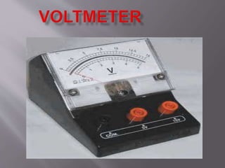


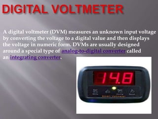


A voltmeter is an instrument used to measure voltage between two points in a circuit. Analog voltmeters use a moving coil and pointer to display voltage proportionally, while digital voltmeters (DVM) use an analog-to-digital converter to provide a numeric readout. Before DVMs, potentiometers were commonly used to measure voltage by balancing the voltage drop across a known resistor against an unknown voltage. Potentiometers work on the principle that voltage drop is proportional to distance in a uniform wire.