SlideShare a Scribd company logo
www.ekeeda.com Contact : 9029006464 Email : care@ekeeda.com
1
P
INTRODUCTION
This chapter has been divided into following topics:-
1. Basic concept of electrical networks
2. Types of Sources
3. Star-Delta Transformation
4. Kirchhoff’s laws
5. Mesh & Nodal Analysis
6. Source Transformation
7. Superposition Theorem
8. Thevenin’s Theorem and Norton’s Theorem
9. Maximum Power Transfer Theorem
ELECTRICAL NETWORK
 All the electrical components are divided into two groups:-
1) Active elements:-
The electrical elements which provides energy for the operation of the
circuit are called Active Elements.
e.g. Voltage and Current source
2) Passive elements:-
The elements which depends on active elements for their working are
called Passive Elements.
e.g. Resistors, Inductors and Capacitors
D.C. Circuits
www.ekeeda.com Contact : 9029006464 Email : care@ekeeda.com
2
Types of Electrical Network
1) Linear Network:-
A network whose parameters (resistor, inductors and capacitor) are always
constant irrespective of the changes in time, voltage, temperature etc. is
known as Linear Network.
2) Non-Linear Network:-
A network whose parameters change their values with change in time,
temperature, voltage etc. is known as Non-Linear Network.
3) Unilateral Network:-
A network whose operation is dependent on the direction of the current
through various elements is called Unilateral Network.
e.g. Circuits consisting of diodes, SCR etc.
4) Bilateral Network:-
A network whose operation is independent of the direction of the current
through various elements is called Bilateral Network.
e.g. Resistive Networks
Types of Sources
The sources are basically classified as:
i) Ideal Source
ii) Practical Source
 Ideal Voltage Source:-
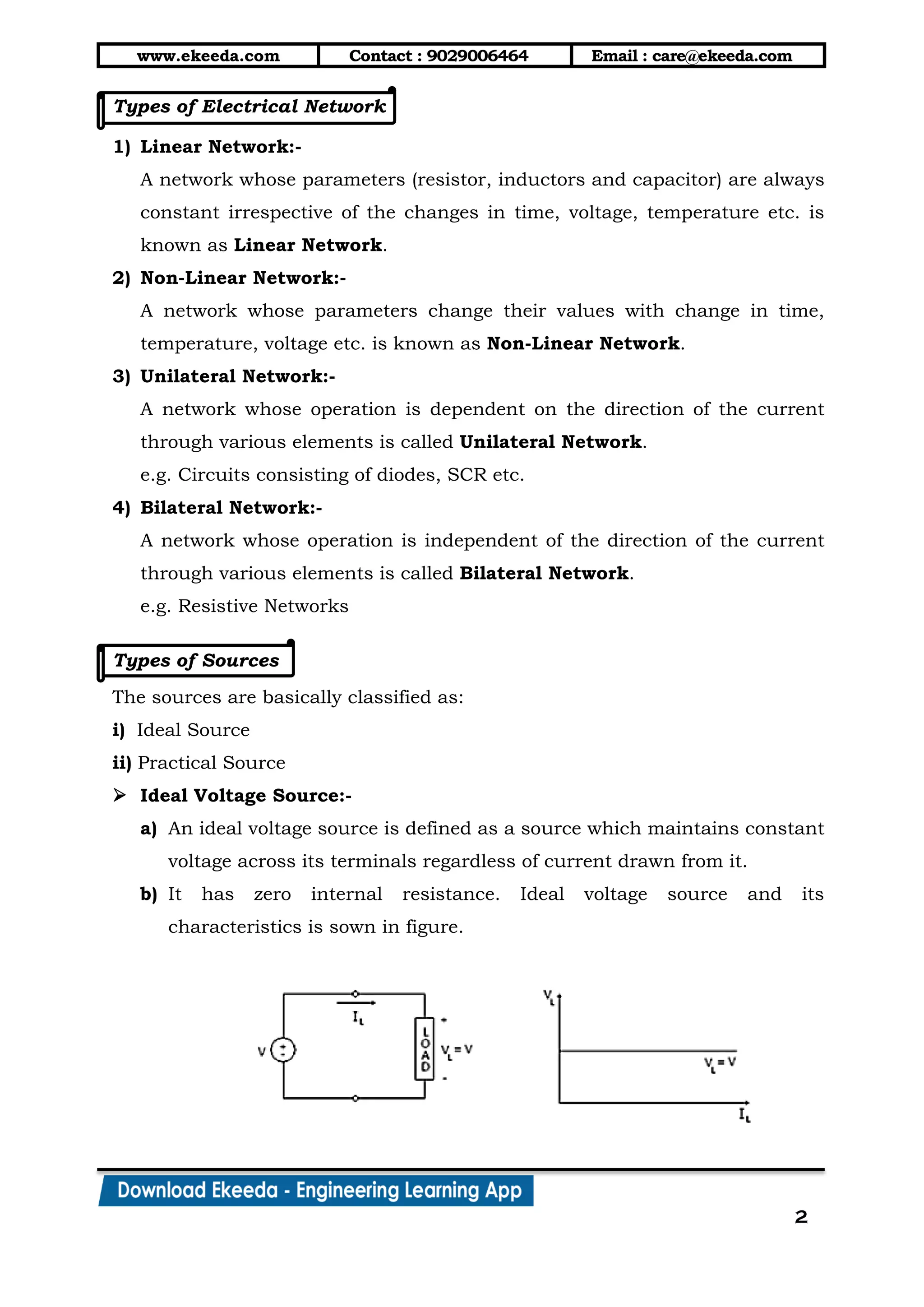
a) An ideal voltage source is defined as a source which maintains constant
voltage across its terminals regardless of current drawn from it.
b) It has zero internal resistance. Ideal voltage source and its
characteristics is sown in figure.
www.ekeeda.com Contact : 9029006464 Email : care@ekeeda.com
3
 Practical Voltage Source:-
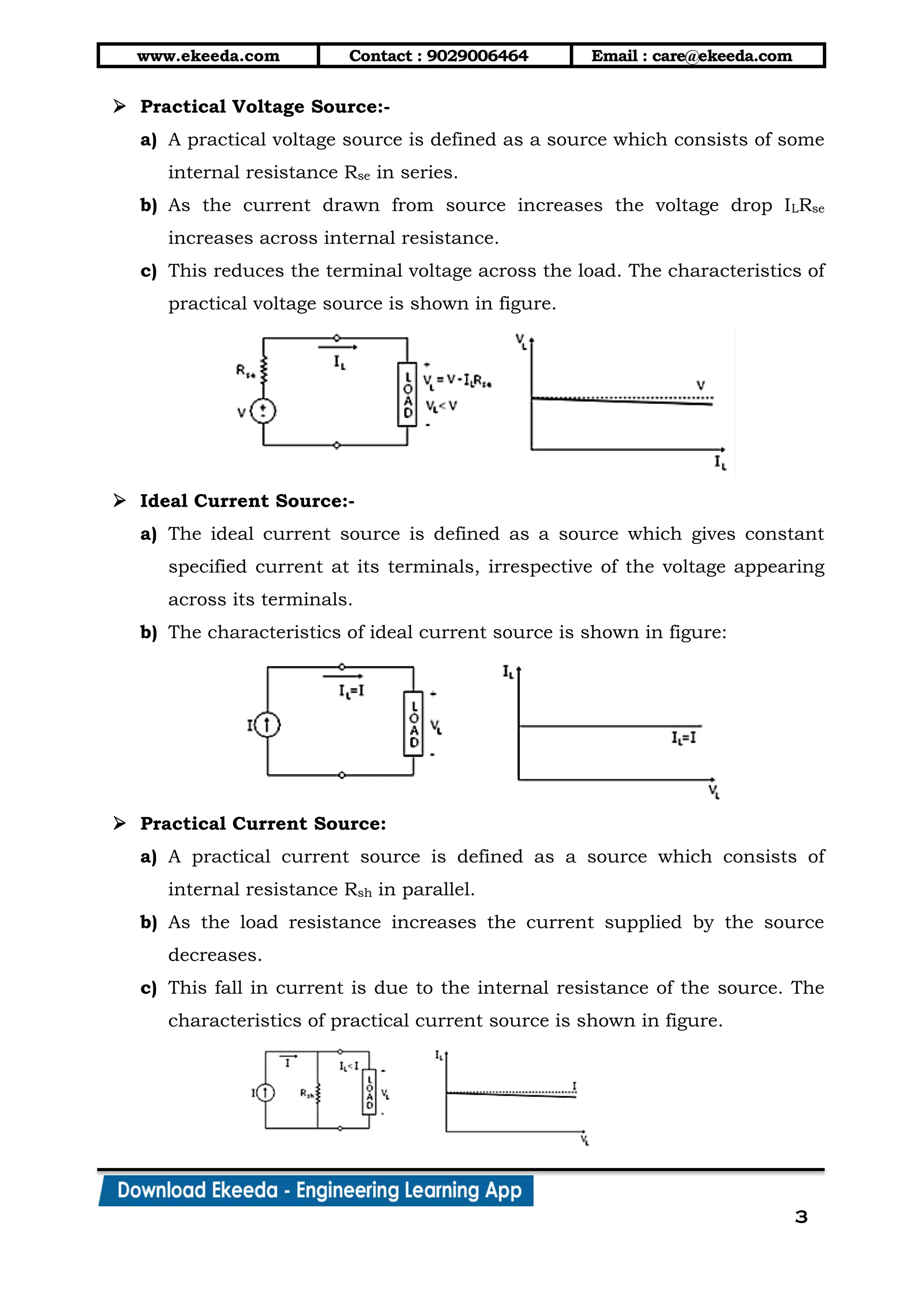
a) A practical voltage source is defined as a source which consists of some
internal resistance Rse in series.
b) As the current drawn from source increases the voltage drop ILRse
increases across internal resistance.
c) This reduces the terminal voltage across the load. The characteristics of
practical voltage source is shown in figure.
 Ideal Current Source:-
a) The ideal current source is defined as a source which gives constant
specified current at its terminals, irrespective of the voltage appearing
across its terminals.
b) The characteristics of ideal current source is shown in figure:
 Practical Current Source:
a) A practical current source is defined as a source which consists of
internal resistance Rsh in parallel.
b) As the load resistance increases the current supplied by the source
decreases.
c) This fall in current is due to the internal resistance of the source. The
characteristics of practical current source is shown in figure.
www.ekeeda.com Contact : 9029006464 Email : care@ekeeda.com
4
SERIES CIRCUIT
1) Consider Resistors R1, R2, …., Rn connected to from a series circuit.
2) Following points can be concluded for series circuit:-
a) The current flowing through each resistor is the same i.e. I.
b) The potential difference across resistors R1, R2, …, Rn are
V1 = IR1, V2 = I R2, …, Vn = IRn respectively.
c) Also applied voltage gets distributed across resistors i.e.
VT = V1 + V2 +….+ Vn.
d) The net or equivalent resistance of the series circuit is given by,
Req = R1 + R2 + … + Rn.
e) There are no junctions and the same current I flow through the single
path.
Voltage Division Rule
Referring to the above figure we have,
T
eq
V
I =
R
T
1 2 n
V
I =
R +R +....+R

Therefore, voltage across R1 is,
1 1 1
1 2 ...
T
n
V
V I R R
R R R
 
   
   
Similarly,
2 2 2
1 2 ...
T
n
V
V I R R
R R R
 
   
   
1 2 ...
T
n n n
n
V
V I R R
R R R
 
   
   
www.ekeeda.com Contact : 9029006464 Email : care@ekeeda.com
5
PARALLEL CIRCUIT
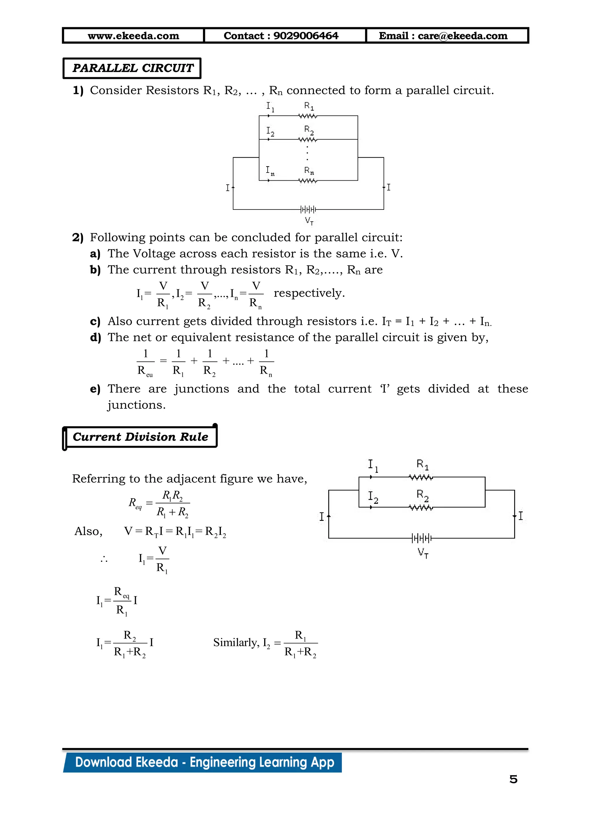
1) Consider Resistors R1, R2, … , Rn connected to form a parallel circuit.
2) Following points can be concluded for parallel circuit:
a) The Voltage across each resistor is the same i.e. V.
b) The current through resistors R1, R2,…., Rn are
1 2 n
1 2 n
V V V
I = ,I = ,...,I =
R R R
respectively.
c) Also current gets divided through resistors i.e. IT = I1 + I2 + … + In.
d) The net or equivalent resistance of the parallel circuit is given by,
eu 1 2 n
1 1 1 1
= + + .... +
R R R R
e) There are junctions and the total current ‘I’ gets divided at these
junctions.
Current Division Rule
Referring to the adjacent figure we have,
1 2
1 2
eq
R R
R
R R


Also, T 1 1 2 2V = R I = R I = R I
1
1
V
I =
R

eq
1
1
R
I = I
R
2 1
1 2
1 2 1 2
R R
I = I Similarly, I
R +R R +R

www.ekeeda.com Contact : 9029006464 Email : care@ekeeda.com
6
DELTA TO STAR AND STAR TO DELTA TRANSFORMATION
1) There are some networks in which the resistances are neither in series nor
in parallel. A familiar case is a three terminal network e.g. delta network or
star network.
2) In such situations, it is not possible to simplify the network by series and
parallel circuit rules. However, converting delta network into star and vice-
versa often simplifies the network and makes it possible to apply series
parallel circuit techniques.
Delta to Star transformation
1) Consider three resistors RA, RB, RC connected in delta to three terminals 1,
2 and 3 as shown in the figure (a). It is desired to replace these three delta
connected resistors by three resistors R1, R2, R3 connected in star so that
the two networks are electrically equivalent.
2) The two arrangements will be electrically equivalent if resistance between
any two terminals of one network is equal to the resistance between the
corresponding terminals of the other network.
(a) (b)
www.ekeeda.com Contact : 9029006464 Email : care@ekeeda.com
7
3) Referring to fig. (a)
Resistance between 1 and 2 = Rc || (RA + RB)
=
 c A B
A B C
R R +R
R +R +R
….(1)
4) Also from figure (b),
Resistance between 1 and 2 = R1 + R2 …. (2)
5) Since, two arrangements are electrically equivalent,
 
1 2
c A B
A B C
R R R
R R
R R R

  
 
….. (3)
Similarly,
 A B C
2 3
A B C
R R +R
R +R =
R +R +R
….. (4)
B C A
3 1
A B C
R (R +R )
R +R =
R +R +R
….. (5)
6) Subtracting equation (4) from equation (3) and adding the result to
equation (5) we get,
B C
1
A B C
R R
R =
R +R +R
….. (6)
Similarly, C A
2
A B C
R R
R =
R +R +R
…... (7)
And A B
3
A B C
R R
R =
R +R +R
….. (8)
www.ekeeda.com Contact : 9029006464 Email : care@ekeeda.com
8
Star to Delta transformation
1) Dividing equation (6) by equation (7), we get
1 B 1 A
B
2 A 2
R R R R
= R =
R R R

2) Dividing equation (6) by equation (8), we get
C1 1 A
C
3 A 3
RR R R
= R =
R R R

3) Substituting the value of RB and RC in equation (6) we have
1 A 1 A
2 3
1
1 A 1 A
A
2 3
2
1
2 3
A
1 1
2 3
2
1
A
1 2 2 3 3 1
1 2 2 3 3 1
A
1
R R R R
R R
R =
R R R R
R + +
R R
R
R R
= R
R R
1+ +
R R
R
= R
R R +R R +R R
R R +R R +R R
R =
R
  
  
  
  
  
   
 
 
 
  
  
   

2 3
A 2 3
1
R R
R = R + R +
R

Similarly, 3 1
B 3 1
2
R R
R = R + R +
R
and 1 2
C 1 2
3
R R
R = R + R +
R
Kirchhoff’s Laws
Entire electric circuit analysis is based on Kirchhoff’s laws. But before
discussing this it is essential to familiarise with some terms:
a) Node:-
Node is a junction where two or more circuit elements are connected
together.
b) Branch:-
An element or number of elements connected between two nodes
constitutes a branch.
c) Loop: Loop is any closed part of the circuit.
www.ekeeda.com Contact : 9029006464 Email : care@ekeeda.com
9
d) Mesh:
Mesh is the most elementary form of the loop and cannot be further
divided into other loops. Hence, all the meshes are loops but all the loops
are not meshes.
KIRCHHOFF’S CURRENT LAW (KCL)
 Statement:
The algebraic sum all the currents meeting at a junction or node in an
electric circuit is zero.
i.e. I = 0
 e.g.
Consider five conductors carrying currents I1, I2, I3, I4 and I5 meeting at
point O as shown below. Assuming the incoming currents to be positive
and outgoing currents negative, we have
1 2 3 4 5I + (-I ) + I + I + (-I ) = 0
1 3 4 2 5I + I + I = I + I
Thus, the above law can also be stated as the sum of currents flowing
towards any junction in an electric circuit is equal to the sum of the
current flowing away from the junction.
www.ekeeda.com Contact : 9029006464 Email : care@ekeeda.com
10
KIRCHHOFF’S VOLTAGE LAW (KVL)
 Statement:
The algebraic sum of all the voltages in any closed mesh or loop is zero.
i.e. IR+ E = 0 
 Sign Conventions:
a) Sign of a battery:-
A rise in voltage is considered as positive, whereas fall in voltage is
considered as negative.
(a) Rise in Voltage (b) Fall in Voltage
b) Sign of I R drop:-
If we go through the resistance in the same direction as the current,
there is fall in the potential so the sign of voltage drop is negative. If we
go opposite to the direction of current flow, there is a rise in potential
and hence, this voltage drop should be given negative sign.
(a) Fall in Voltage (b) Rise in Voltage
Mesh Analysis
1) In this method, KVL is applied to a network to write mesh equations in
terms of mesh currents instead of branch currents.
2) Each mesh is assigned a separate mesh current. KVL is then applied to
write equations in terms of unknown mesh currents.
3) The number of equations formed is equal to the number of unknown mesh
currents. Once the mesh currents are known, the branch currents can be
easily determined.
4) Steps to be followed in Mesh Analysis:
a) Identify the mesh, assign a direction to it and assign an unknown
current in each mesh.
www.ekeeda.com Contact : 9029006464 Email : care@ekeeda.com
11
b) Assign the polarities for voltage across the branches.
c) Apply KVL around each mesh.
d) Solve the simultaneous equations for unknown mesh currents.
 Advantages:
1) Simpler method as compared to Kirchhoff’s Branch current method.
2) Currents through all the branches of a given network can be found.
 Disadvantages:
1) If the current through only a particular branch is required, then this
method is lengthy.
2) Inconvenient for the circuits containing constant current source.
Nodal Analysis
1) In this method, one of the node is taken as the reference node and the
potential of all the remaining nodes in the circuit are measured w.r.t. this
reference node.
2) For finding out these voltages, KCL is used as the various junctions. Thus
for an electrical network having ‘n’ nodes the number of simultaneous
equations to be solved is (n-1).
3) Steps to be followed in Nodal Analysis:
a) Assuming that network has ‘n’ nodes, assign a reference node and the
reference directions and assign node voltages.
b) Apply KCL at each node except for references node.
c) Solve the simultaneous equations for the unknown node voltages.
d) Using these node voltages, find any branch currents required.
www.ekeeda.com Contact : 9029006464 Email : care@ekeeda.com
12
Source Transformation and Source Shifting
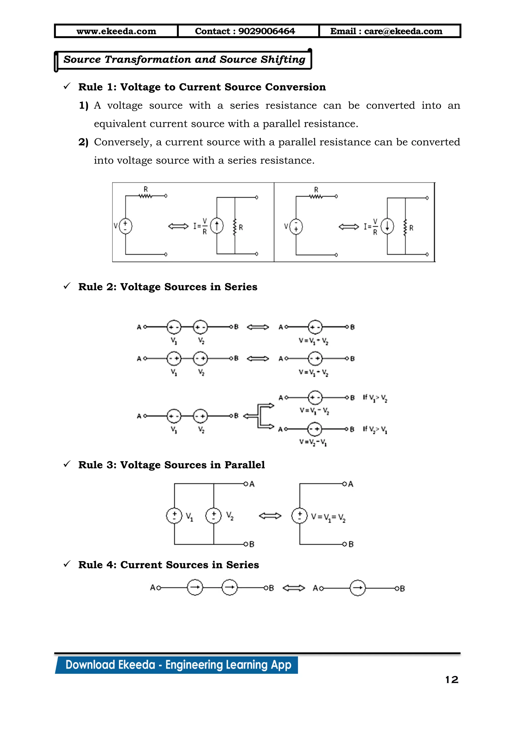
 Rule 1: Voltage to Current Source Conversion
1) A voltage source with a series resistance can be converted into an
equivalent current source with a parallel resistance.
2) Conversely, a current source with a parallel resistance can be converted
into voltage source with a series resistance.
 Rule 2: Voltage Sources in Series
 Rule 3: Voltage Sources in Parallel
 Rule 4: Current Sources in Series
www.ekeeda.com Contact : 9029006464 Email : care@ekeeda.com
13
 Rule 6: Shifting of Voltage Source
 Rule 5: Current Sources in Parallel
 Rule 7: Shifting of Current Source
www.ekeeda.com Contact : 9029006464 Email : care@ekeeda.com
14
Superposition Theorem
 Statement:-
In a linear network containing more than one active source, the resultant
current in any element is the algebraic sum of all the currents that would
be produced by each source acting alone, all the other sources being
replaced by their respective internal resistances.
1) The constant voltage sources are represented by their internal
resistance if given. If it is not given replace it by short circuit.
2) The constant current sources are represented by infinite resistance i.e.
open circuit.
 Advantages:
1) The current through a particular branch can be found very quickly.
 Disadvantages:
1) This method can be used only for those circuits containing more than
one source.
2) If currents through all the branches are required then this method is
lengthy.
Thevenin’s Theorem
 Statement:-
Any two terminal bilateral, linear network containing passive elements can
be converted into a single equivalent voltage source known as ‘Thevenin’s
voltage source’ in series with a single equivalent resistor known a
‘Thevenin’s resistance’.
 Steps to be followed in Thevenin’s Theorem:
1) Remove the load resistance RL.
2) Find open circuit voltage VTH across points A and B.
www.ekeeda.com Contact : 9029006464 Email : care@ekeeda.com
15
3) Find the resistance RTH as seen from point A and B with all the sources
replaced by their internal resistances.
4) Replace the entire network by voltage source VTH in series with
resistance RTH.
5) Find the current through RL using ohm’s law.
TH
L
TH L
V
I =
R +R .
 Advantages:
1) It reduces a complex circuit to a simple circuit i.e. single voltage source
and a single resistance.
2) It greatly simplifies the portion of the circuit of lesser interest and
enables us to view the action of the output part directly.
3) The theorem is used to find the current in a particular branch of a
network.
 Disadvantages:
1) If currents through all the branches are required then this method is
lengthy.
www.ekeeda.com Contact : 9029006464 Email : care@ekeeda.com
16
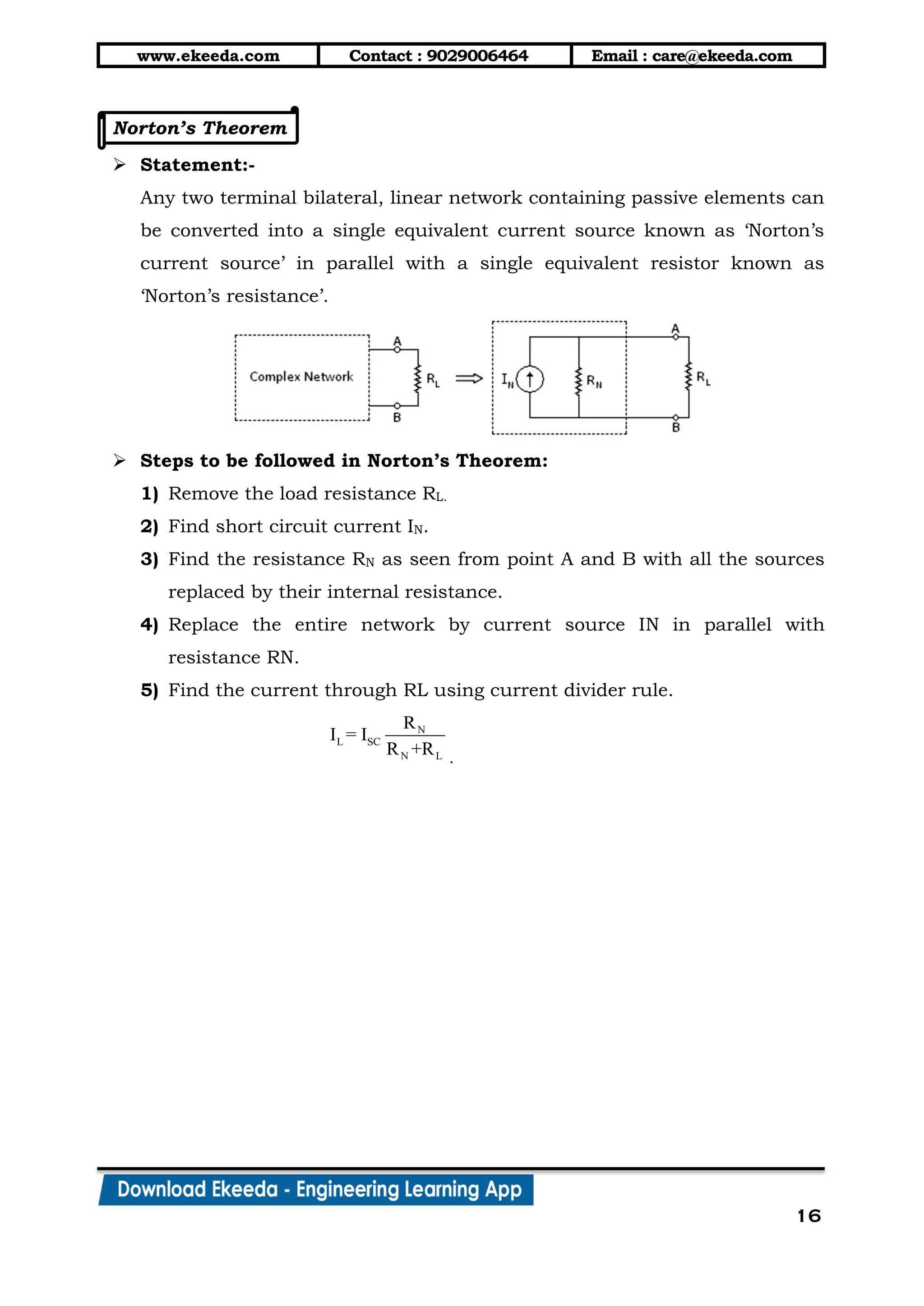
Norton’s Theorem
 Statement:-
Any two terminal bilateral, linear network containing passive elements can
be converted into a single equivalent current source known as ‘Norton’s
current source’ in parallel with a single equivalent resistor known as
‘Norton’s resistance’.
 Steps to be followed in Norton’s Theorem:
1) Remove the load resistance RL.
2) Find short circuit current IN.
3) Find the resistance RN as seen from point A and B with all the sources
replaced by their internal resistance.
4) Replace the entire network by current source IN in parallel with
resistance RN.
5) Find the current through RL using current divider rule.
N
L SC
N L
R
I = I
R +R .
www.ekeeda.com Contact : 9029006464 Email : care@ekeeda.com
17
Maximum Power Transfer Theorem
 Statement:-
In any two terminal bilateral, linear network containing passive elements
maximum power is delivered to a load from a source when the load
resistance is made equal to the source resistance.
i.e. PLoad is maximum only when RL = RS
 Proof:-
1) Consider a load resistance RL connected across the terminals A and B
of a network which consists of a voltage source ES with internal
resistance RS.
2) The circuit current is S
L S
E
I =
R +R
 Power consumed by the load is,
2
2 S L
L L 2
L S
E R
P = I R =
R +R
……. (1)
3) For a given source or circuit ES and RS are constant. Therefore power
delivered to the load depends on RL only. Thus, for PL to be maximum
L
L
dP
=0
dR
www.ekeeda.com Contact : 9029006464 Email : care@ekeeda.com
18
4) Therefore, differentiating equation (1) we get,
 2
L S L L S2L
S 4
L L S
2 2
2 S LL
S 4
L L S
2 S LL
S 3
L L S
R +R (1)-(R ) 2R +RdP
= E
dR R +R
R -RdP
= E
dR R +R
R -RdP
= E
dR R +R
 
 
 
 
 
 
 
 
 
But, L
L
dP
=0
dR
2
3
0
0
S L
S
L S
S L
L S
R R
E
R R
R R
R R
 
  
 
  
 
hence, the Proof.
5) Also maximum power transferred to the load is,
2 2
S L S S
Lmax 2 2
L S S
2
S
Lmax
s
E R E R
P = =
R +R 2R
E
P =
4R


More Related Content

What's hot

EC6202 ELECTRONIC DEVICES AND CIRCUITS Unit 1
EC6202 ELECTRONIC DEVICES AND CIRCUITS Unit 1EC6202 ELECTRONIC DEVICES AND CIRCUITS Unit 1
EC6202 ELECTRONIC DEVICES AND CIRCUITS Unit 1
RMK ENGINEERING COLLEGE, CHENNAI
 
Basic concept of electronics.
Basic concept of electronics.Basic concept of electronics.
Basic concept of electronics.
creatjet3d labs
 
CE, CB, CC AMPLIFIERS
 CE, CB, CC AMPLIFIERS CE, CB, CC AMPLIFIERS
CE, CB, CC AMPLIFIERS
bharath405
 
Circuit Analysis – DC Circuits
Circuit Analysis – DC CircuitsCircuit Analysis – DC Circuits
Circuit Analysis – DC Circuits
Vesa Linja-aho
 
EC8353 ELECTRONIC DEVICES AND CIRCUITS Unit 1
EC8353 ELECTRONIC DEVICES AND CIRCUITS Unit 1EC8353 ELECTRONIC DEVICES AND CIRCUITS Unit 1
EC8353 ELECTRONIC DEVICES AND CIRCUITS Unit 1
RMK ENGINEERING COLLEGE, CHENNAI
 
Electrical circuitsand methods of network analysis
Electrical circuitsand methods of network analysisElectrical circuitsand methods of network analysis
Electrical circuitsand methods of network analysis
University of Potsdam
 
Introduction To Electrical Engineering
Introduction To Electrical EngineeringIntroduction To Electrical Engineering
Introduction To Electrical Engineering
mike parks
 
Arduino dc motor
Arduino dc motor Arduino dc motor
Arduino dc motor
Hajer Dahech
 
Electrodynamometer wattmeter
Electrodynamometer wattmeterElectrodynamometer wattmeter
Electrodynamometer wattmeter
T Babu SJCE - ICE
 
Ge 2151 basic electrical electronics engineering
Ge 2151 basic electrical electronics engineering Ge 2151 basic electrical electronics engineering
Ge 2151 basic electrical electronics engineering dineshanand810
 
Digital Voltmeter, Digital Multi-meter, Digital frequency meter
Digital Voltmeter, Digital Multi-meter, Digital frequency meterDigital Voltmeter, Digital Multi-meter, Digital frequency meter
Digital Voltmeter, Digital Multi-meter, Digital frequency meter
Dr Naim R Kidwai
 
Magnetic circuits
Magnetic circuitsMagnetic circuits
Magnetic circuits
Abhinay Potlabathini
 
Electronic devices-and-circuit-theory-10th-ed-boylestad-chapter-1
Electronic devices-and-circuit-theory-10th-ed-boylestad-chapter-1Electronic devices-and-circuit-theory-10th-ed-boylestad-chapter-1
Electronic devices-and-circuit-theory-10th-ed-boylestad-chapter-1Shiwam Isrie
 
Basic electronics
Basic electronics Basic electronics
Basic electronics
arunavasava
 
Lecture 3
Lecture 3Lecture 3
Lecture 3
Forward2025
 
DIGITAL MULTIMETER PPT
DIGITAL MULTIMETER PPTDIGITAL MULTIMETER PPT
DIGITAL MULTIMETER PPT
prapti borthakur
 
Ac to Dc converter
Ac to Dc converterAc to Dc converter
Ac to Dc converter
JAMEEL AHMED KHOSO
 

What's hot (20)

EC6202 ELECTRONIC DEVICES AND CIRCUITS Unit 1
EC6202 ELECTRONIC DEVICES AND CIRCUITS Unit 1EC6202 ELECTRONIC DEVICES AND CIRCUITS Unit 1
EC6202 ELECTRONIC DEVICES AND CIRCUITS Unit 1
 
Basic concept of electronics.
Basic concept of electronics.Basic concept of electronics.
Basic concept of electronics.
 
CE, CB, CC AMPLIFIERS
 CE, CB, CC AMPLIFIERS CE, CB, CC AMPLIFIERS
CE, CB, CC AMPLIFIERS
 
Circuit Analysis – DC Circuits
Circuit Analysis – DC CircuitsCircuit Analysis – DC Circuits
Circuit Analysis – DC Circuits
 
EC8353 ELECTRONIC DEVICES AND CIRCUITS Unit 1
EC8353 ELECTRONIC DEVICES AND CIRCUITS Unit 1EC8353 ELECTRONIC DEVICES AND CIRCUITS Unit 1
EC8353 ELECTRONIC DEVICES AND CIRCUITS Unit 1
 
Electrical circuitsand methods of network analysis
Electrical circuitsand methods of network analysisElectrical circuitsand methods of network analysis
Electrical circuitsand methods of network analysis
 
Introduction To Electrical Engineering
Introduction To Electrical EngineeringIntroduction To Electrical Engineering
Introduction To Electrical Engineering
 
Arduino dc motor
Arduino dc motor Arduino dc motor
Arduino dc motor
 
Electrodynamometer wattmeter
Electrodynamometer wattmeterElectrodynamometer wattmeter
Electrodynamometer wattmeter
 
Ge 2151 basic electrical electronics engineering
Ge 2151 basic electrical electronics engineering Ge 2151 basic electrical electronics engineering
Ge 2151 basic electrical electronics engineering
 
Digital Voltmeter, Digital Multi-meter, Digital frequency meter
Digital Voltmeter, Digital Multi-meter, Digital frequency meterDigital Voltmeter, Digital Multi-meter, Digital frequency meter
Digital Voltmeter, Digital Multi-meter, Digital frequency meter
 
Magnetic circuits
Magnetic circuitsMagnetic circuits
Magnetic circuits
 
Electronic devices-and-circuit-theory-10th-ed-boylestad-chapter-1
Electronic devices-and-circuit-theory-10th-ed-boylestad-chapter-1Electronic devices-and-circuit-theory-10th-ed-boylestad-chapter-1
Electronic devices-and-circuit-theory-10th-ed-boylestad-chapter-1
 
Ac theory
Ac theoryAc theory
Ac theory
 
Basic electronics
Basic electronics Basic electronics
Basic electronics
 
Lecture 3
Lecture 3Lecture 3
Lecture 3
 
DIGITAL MULTIMETER PPT
DIGITAL MULTIMETER PPTDIGITAL MULTIMETER PPT
DIGITAL MULTIMETER PPT
 
Energy meter
Energy meterEnergy meter
Energy meter
 
Ac to Dc converter
Ac to Dc converterAc to Dc converter
Ac to Dc converter
 
Dac s05
Dac s05Dac s05
Dac s05
 

Similar to Dc circuits

Electrical and Electronics Engineering
Electrical and Electronics EngineeringElectrical and Electronics Engineering
Electrical and Electronics Engineering
Ekeeda
 
Basic Electrical (Short Course).pptx
Basic Electrical (Short Course).pptxBasic Electrical (Short Course).pptx
Basic Electrical (Short Course).pptx
BudhadityaBiswas5
 
RGPV BE Ist SEM BEE104 Unit I
RGPV BE Ist SEM BEE104 Unit IRGPV BE Ist SEM BEE104 Unit I
RGPV BE Ist SEM BEE104 Unit I
Mani Deep Dutt
 
Cureent, Resistance & Kirchhoff’s Rules.pptx
Cureent, Resistance & Kirchhoff’s Rules.pptxCureent, Resistance & Kirchhoff’s Rules.pptx
Cureent, Resistance & Kirchhoff’s Rules.pptx
ChuksAbbey
 
Project
ProjectProject
Project
mohsena8
 
Electrical circuits
Electrical circuitsElectrical circuits
Electrical circuits
University of Potsdam
 
3- Ch03- Methods Of Analysis-Sadiku
3- Ch03- Methods Of Analysis-Sadiku3- Ch03- Methods Of Analysis-Sadiku
3- Ch03- Methods Of Analysis-Sadiku
Tracy Morgan
 
Topic 1 b_basic_concepts_and_theorem
Topic 1 b_basic_concepts_and_theoremTopic 1 b_basic_concepts_and_theorem
Topic 1 b_basic_concepts_and_theorem
Gabriel O'Brien
 
Dc circuits
Dc circuitsDc circuits
Dc circuits
Vaibhav Tandel
 
DC circuit
DC circuitDC circuit
DC circuit
prempanigrahi
 
Sesión de Laboratorio 3: Leyes de Kirchhoff, Circuitos RC y Diodos
Sesión de Laboratorio 3: Leyes de Kirchhoff, Circuitos RC y DiodosSesión de Laboratorio 3: Leyes de Kirchhoff, Circuitos RC y Diodos
Sesión de Laboratorio 3: Leyes de Kirchhoff, Circuitos RC y Diodos
Javier García Molleja
 
Two marks ca 2017 reg final
Two marks ca  2017 reg finalTwo marks ca  2017 reg final
Two marks ca 2017 reg final
Sridhar Jayaraman
 
dependent_sources.pdf
dependent_sources.pdfdependent_sources.pdf
dependent_sources.pdf
SoniaJoshi25
 
750913A02101 Electrical Circuits.pdf
750913A02101  Electrical Circuits.pdf750913A02101  Electrical Circuits.pdf
750913A02101 Electrical Circuits.pdf
k vimal kumar
 
Bai thi nghiem_linear_circuit_cttt
Bai thi nghiem_linear_circuit_ctttBai thi nghiem_linear_circuit_cttt
Bai thi nghiem_linear_circuit_ctttkutyonljne
 
Three phase circuits
Three phase circuitsThree phase circuits
Three phase circuits
Ekeeda
 
Electric Circuits Ppt Slides
Electric Circuits Ppt SlidesElectric Circuits Ppt Slides
Electric Circuits Ppt Slides
guest5e66ab3
 
2nd year iv sem emi lab manual
2nd year iv sem emi lab manual2nd year iv sem emi lab manual
2nd year iv sem emi lab manual
HARISH KUMAR MAHESHWARI
 
Elements of electrical engineering dc circuits
Elements of electrical engineering dc circuitsElements of electrical engineering dc circuits
Elements of electrical engineering dc circuits
Hardik Lathiya
 
BEEE-UNIT 1.pptx
BEEE-UNIT 1.pptxBEEE-UNIT 1.pptx
BEEE-UNIT 1.pptx
Gigi203211
 

Similar to Dc circuits (20)

Electrical and Electronics Engineering
Electrical and Electronics EngineeringElectrical and Electronics Engineering
Electrical and Electronics Engineering
 
Basic Electrical (Short Course).pptx
Basic Electrical (Short Course).pptxBasic Electrical (Short Course).pptx
Basic Electrical (Short Course).pptx
 
RGPV BE Ist SEM BEE104 Unit I
RGPV BE Ist SEM BEE104 Unit IRGPV BE Ist SEM BEE104 Unit I
RGPV BE Ist SEM BEE104 Unit I
 
Cureent, Resistance & Kirchhoff’s Rules.pptx
Cureent, Resistance & Kirchhoff’s Rules.pptxCureent, Resistance & Kirchhoff’s Rules.pptx
Cureent, Resistance & Kirchhoff’s Rules.pptx
 
Project
ProjectProject
Project
 
Electrical circuits
Electrical circuitsElectrical circuits
Electrical circuits
 
3- Ch03- Methods Of Analysis-Sadiku
3- Ch03- Methods Of Analysis-Sadiku3- Ch03- Methods Of Analysis-Sadiku
3- Ch03- Methods Of Analysis-Sadiku
 
Topic 1 b_basic_concepts_and_theorem
Topic 1 b_basic_concepts_and_theoremTopic 1 b_basic_concepts_and_theorem
Topic 1 b_basic_concepts_and_theorem
 
Dc circuits
Dc circuitsDc circuits
Dc circuits
 
DC circuit
DC circuitDC circuit
DC circuit
 
Sesión de Laboratorio 3: Leyes de Kirchhoff, Circuitos RC y Diodos
Sesión de Laboratorio 3: Leyes de Kirchhoff, Circuitos RC y DiodosSesión de Laboratorio 3: Leyes de Kirchhoff, Circuitos RC y Diodos
Sesión de Laboratorio 3: Leyes de Kirchhoff, Circuitos RC y Diodos
 
Two marks ca 2017 reg final
Two marks ca  2017 reg finalTwo marks ca  2017 reg final
Two marks ca 2017 reg final
 
dependent_sources.pdf
dependent_sources.pdfdependent_sources.pdf
dependent_sources.pdf
 
750913A02101 Electrical Circuits.pdf
750913A02101  Electrical Circuits.pdf750913A02101  Electrical Circuits.pdf
750913A02101 Electrical Circuits.pdf
 
Bai thi nghiem_linear_circuit_cttt
Bai thi nghiem_linear_circuit_ctttBai thi nghiem_linear_circuit_cttt
Bai thi nghiem_linear_circuit_cttt
 
Three phase circuits
Three phase circuitsThree phase circuits
Three phase circuits
 
Electric Circuits Ppt Slides
Electric Circuits Ppt SlidesElectric Circuits Ppt Slides
Electric Circuits Ppt Slides
 
2nd year iv sem emi lab manual
2nd year iv sem emi lab manual2nd year iv sem emi lab manual
2nd year iv sem emi lab manual
 
Elements of electrical engineering dc circuits
Elements of electrical engineering dc circuitsElements of electrical engineering dc circuits
Elements of electrical engineering dc circuits
 
BEEE-UNIT 1.pptx
BEEE-UNIT 1.pptxBEEE-UNIT 1.pptx
BEEE-UNIT 1.pptx
 

More from Ekeeda

Thermit welding
Thermit weldingThermit welding
Thermit welding
Ekeeda
 
Plasma arc welding
Plasma arc weldingPlasma arc welding
Plasma arc welding
Ekeeda
 
Friction welding
Friction weldingFriction welding
Friction welding
Ekeeda
 
Trusses
TrussesTrusses
Trusses
Ekeeda
 
Space forces
Space forcesSpace forces
Space forces
Ekeeda
 
Kinetics of particles work energy method
Kinetics of particles work energy methodKinetics of particles work energy method
Kinetics of particles work energy method
Ekeeda
 
Kinetics of particles newton's 2nd law
Kinetics of particles newton's 2nd lawKinetics of particles newton's 2nd law
Kinetics of particles newton's 2nd law
Ekeeda
 
Kinetics of particles impulse momentum method
Kinetics of particles impulse momentum methodKinetics of particles impulse momentum method
Kinetics of particles impulse momentum method
Ekeeda
 
Kinematics of rigid bodies
Kinematics of rigid bodiesKinematics of rigid bodies
Kinematics of rigid bodies
Ekeeda
 
Kinematics of particles
Kinematics of particlesKinematics of particles
Kinematics of particles
Ekeeda
 
Friction
FrictionFriction
Friction
Ekeeda
 
Coplanar forces res & comp of forces - for merge
Coplanar forces res & comp of forces - for mergeCoplanar forces res & comp of forces - for merge
Coplanar forces res & comp of forces - for merge
Ekeeda
 
Coplanar forces equilibrium
Coplanar forces equilibriumCoplanar forces equilibrium
Coplanar forces equilibrium
Ekeeda
 
Centroid and centre of gravity
Centroid and centre of gravityCentroid and centre of gravity
Centroid and centre of gravity
Ekeeda
 
5. important engineering material
5. important engineering material5. important engineering material
5. important engineering material
Ekeeda
 
4. phase rule
4. phase rule4. phase rule
4. phase rule
Ekeeda
 
3. lubricants
3. lubricants3. lubricants
3. lubricants
Ekeeda
 
2. polymers rubbers
2. polymers   rubbers2. polymers   rubbers
2. polymers rubbers
Ekeeda
 
1. water
1. water1. water
1. water
Ekeeda
 
Merged document 4
Merged document 4Merged document 4
Merged document 4
Ekeeda
 

More from Ekeeda (20)

Thermit welding
Thermit weldingThermit welding
Thermit welding
 
Plasma arc welding
Plasma arc weldingPlasma arc welding
Plasma arc welding
 
Friction welding
Friction weldingFriction welding
Friction welding
 
Trusses
TrussesTrusses
Trusses
 
Space forces
Space forcesSpace forces
Space forces
 
Kinetics of particles work energy method
Kinetics of particles work energy methodKinetics of particles work energy method
Kinetics of particles work energy method
 
Kinetics of particles newton's 2nd law
Kinetics of particles newton's 2nd lawKinetics of particles newton's 2nd law
Kinetics of particles newton's 2nd law
 
Kinetics of particles impulse momentum method
Kinetics of particles impulse momentum methodKinetics of particles impulse momentum method
Kinetics of particles impulse momentum method
 
Kinematics of rigid bodies
Kinematics of rigid bodiesKinematics of rigid bodies
Kinematics of rigid bodies
 
Kinematics of particles
Kinematics of particlesKinematics of particles
Kinematics of particles
 
Friction
FrictionFriction
Friction
 
Coplanar forces res & comp of forces - for merge
Coplanar forces res & comp of forces - for mergeCoplanar forces res & comp of forces - for merge
Coplanar forces res & comp of forces - for merge
 
Coplanar forces equilibrium
Coplanar forces equilibriumCoplanar forces equilibrium
Coplanar forces equilibrium
 
Centroid and centre of gravity
Centroid and centre of gravityCentroid and centre of gravity
Centroid and centre of gravity
 
5. important engineering material
5. important engineering material5. important engineering material
5. important engineering material
 
4. phase rule
4. phase rule4. phase rule
4. phase rule
 
3. lubricants
3. lubricants3. lubricants
3. lubricants
 
2. polymers rubbers
2. polymers   rubbers2. polymers   rubbers
2. polymers rubbers
 
1. water
1. water1. water
1. water
 
Merged document 4
Merged document 4Merged document 4
Merged document 4
 

Recently uploaded

Cosmetic shop management system project report.pdf
Cosmetic shop management system project report.pdfCosmetic shop management system project report.pdf
Cosmetic shop management system project report.pdf
Kamal Acharya
 
Immunizing Image Classifiers Against Localized Adversary Attacks
Immunizing Image Classifiers Against Localized Adversary AttacksImmunizing Image Classifiers Against Localized Adversary Attacks
Immunizing Image Classifiers Against Localized Adversary Attacks
gerogepatton
 
Industrial Training at Shahjalal Fertilizer Company Limited (SFCL)
Industrial Training at Shahjalal Fertilizer Company Limited (SFCL)Industrial Training at Shahjalal Fertilizer Company Limited (SFCL)
Industrial Training at Shahjalal Fertilizer Company Limited (SFCL)
MdTanvirMahtab2
 
DESIGN A COTTON SEED SEPARATION MACHINE.docx
DESIGN A COTTON SEED SEPARATION MACHINE.docxDESIGN A COTTON SEED SEPARATION MACHINE.docx
DESIGN A COTTON SEED SEPARATION MACHINE.docx
FluxPrime1
 
Student information management system project report ii.pdf
Student information management system project report ii.pdfStudent information management system project report ii.pdf
Student information management system project report ii.pdf
Kamal Acharya
 
Governing Equations for Fundamental Aerodynamics_Anderson2010.pdf
Governing Equations for Fundamental Aerodynamics_Anderson2010.pdfGoverning Equations for Fundamental Aerodynamics_Anderson2010.pdf
Governing Equations for Fundamental Aerodynamics_Anderson2010.pdf
WENKENLI1
 
ASME IX(9) 2007 Full Version .pdf
ASME IX(9)  2007 Full Version       .pdfASME IX(9)  2007 Full Version       .pdf
ASME IX(9) 2007 Full Version .pdf
AhmedHussein950959
 
AP LAB PPT.pdf ap lab ppt no title specific
AP LAB PPT.pdf ap lab ppt no title specificAP LAB PPT.pdf ap lab ppt no title specific
AP LAB PPT.pdf ap lab ppt no title specific
BrazilAccount1
 
一比一原版(SFU毕业证)西蒙菲莎大学毕业证成绩单如何办理
一比一原版(SFU毕业证)西蒙菲莎大学毕业证成绩单如何办理一比一原版(SFU毕业证)西蒙菲莎大学毕业证成绩单如何办理
一比一原版(SFU毕业证)西蒙菲莎大学毕业证成绩单如何办理
bakpo1
 
Investor-Presentation-Q1FY2024 investor presentation document.pptx
Investor-Presentation-Q1FY2024 investor presentation document.pptxInvestor-Presentation-Q1FY2024 investor presentation document.pptx
Investor-Presentation-Q1FY2024 investor presentation document.pptx
AmarGB2
 
一比一原版(UofT毕业证)多伦多大学毕业证成绩单如何办理
一比一原版(UofT毕业证)多伦多大学毕业证成绩单如何办理一比一原版(UofT毕业证)多伦多大学毕业证成绩单如何办理
一比一原版(UofT毕业证)多伦多大学毕业证成绩单如何办理
ydteq
 
HYDROPOWER - Hydroelectric power generation
HYDROPOWER - Hydroelectric power generationHYDROPOWER - Hydroelectric power generation
HYDROPOWER - Hydroelectric power generation
Robbie Edward Sayers
 
一比一原版(IIT毕业证)伊利诺伊理工大学毕业证成绩单专业办理
一比一原版(IIT毕业证)伊利诺伊理工大学毕业证成绩单专业办理一比一原版(IIT毕业证)伊利诺伊理工大学毕业证成绩单专业办理
一比一原版(IIT毕业证)伊利诺伊理工大学毕业证成绩单专业办理
zwunae
 
Pile Foundation by Venkatesh Taduvai (Sub Geotechnical Engineering II)-conver...
Pile Foundation by Venkatesh Taduvai (Sub Geotechnical Engineering II)-conver...Pile Foundation by Venkatesh Taduvai (Sub Geotechnical Engineering II)-conver...
Pile Foundation by Venkatesh Taduvai (Sub Geotechnical Engineering II)-conver...
AJAYKUMARPUND1
 
Railway Signalling Principles Edition 3.pdf
Railway Signalling Principles Edition 3.pdfRailway Signalling Principles Edition 3.pdf
Railway Signalling Principles Edition 3.pdf
TeeVichai
 
block diagram and signal flow graph representation
block diagram and signal flow graph representationblock diagram and signal flow graph representation
block diagram and signal flow graph representation
Divya Somashekar
 
power quality voltage fluctuation UNIT - I.pptx
power quality voltage fluctuation UNIT - I.pptxpower quality voltage fluctuation UNIT - I.pptx
power quality voltage fluctuation UNIT - I.pptx
ViniHema
 
road safety engineering r s e unit 3.pdf
road safety engineering  r s e unit 3.pdfroad safety engineering  r s e unit 3.pdf
road safety engineering r s e unit 3.pdf
VENKATESHvenky89705
 
Planning Of Procurement o different goods and services
Planning Of Procurement o different goods and servicesPlanning Of Procurement o different goods and services
Planning Of Procurement o different goods and services
JoytuBarua2
 
Design and Analysis of Algorithms-DP,Backtracking,Graphs,B&B
Design and Analysis of Algorithms-DP,Backtracking,Graphs,B&BDesign and Analysis of Algorithms-DP,Backtracking,Graphs,B&B
Design and Analysis of Algorithms-DP,Backtracking,Graphs,B&B
Sreedhar Chowdam
 

Recently uploaded (20)

Cosmetic shop management system project report.pdf
Cosmetic shop management system project report.pdfCosmetic shop management system project report.pdf
Cosmetic shop management system project report.pdf
 
Immunizing Image Classifiers Against Localized Adversary Attacks
Immunizing Image Classifiers Against Localized Adversary AttacksImmunizing Image Classifiers Against Localized Adversary Attacks
Immunizing Image Classifiers Against Localized Adversary Attacks
 
Industrial Training at Shahjalal Fertilizer Company Limited (SFCL)
Industrial Training at Shahjalal Fertilizer Company Limited (SFCL)Industrial Training at Shahjalal Fertilizer Company Limited (SFCL)
Industrial Training at Shahjalal Fertilizer Company Limited (SFCL)
 
DESIGN A COTTON SEED SEPARATION MACHINE.docx
DESIGN A COTTON SEED SEPARATION MACHINE.docxDESIGN A COTTON SEED SEPARATION MACHINE.docx
DESIGN A COTTON SEED SEPARATION MACHINE.docx
 
Student information management system project report ii.pdf
Student information management system project report ii.pdfStudent information management system project report ii.pdf
Student information management system project report ii.pdf
 
Governing Equations for Fundamental Aerodynamics_Anderson2010.pdf
Governing Equations for Fundamental Aerodynamics_Anderson2010.pdfGoverning Equations for Fundamental Aerodynamics_Anderson2010.pdf
Governing Equations for Fundamental Aerodynamics_Anderson2010.pdf
 
ASME IX(9) 2007 Full Version .pdf
ASME IX(9)  2007 Full Version       .pdfASME IX(9)  2007 Full Version       .pdf
ASME IX(9) 2007 Full Version .pdf
 
AP LAB PPT.pdf ap lab ppt no title specific
AP LAB PPT.pdf ap lab ppt no title specificAP LAB PPT.pdf ap lab ppt no title specific
AP LAB PPT.pdf ap lab ppt no title specific
 
一比一原版(SFU毕业证)西蒙菲莎大学毕业证成绩单如何办理
一比一原版(SFU毕业证)西蒙菲莎大学毕业证成绩单如何办理一比一原版(SFU毕业证)西蒙菲莎大学毕业证成绩单如何办理
一比一原版(SFU毕业证)西蒙菲莎大学毕业证成绩单如何办理
 
Investor-Presentation-Q1FY2024 investor presentation document.pptx
Investor-Presentation-Q1FY2024 investor presentation document.pptxInvestor-Presentation-Q1FY2024 investor presentation document.pptx
Investor-Presentation-Q1FY2024 investor presentation document.pptx
 
一比一原版(UofT毕业证)多伦多大学毕业证成绩单如何办理
一比一原版(UofT毕业证)多伦多大学毕业证成绩单如何办理一比一原版(UofT毕业证)多伦多大学毕业证成绩单如何办理
一比一原版(UofT毕业证)多伦多大学毕业证成绩单如何办理
 
HYDROPOWER - Hydroelectric power generation
HYDROPOWER - Hydroelectric power generationHYDROPOWER - Hydroelectric power generation
HYDROPOWER - Hydroelectric power generation
 
一比一原版(IIT毕业证)伊利诺伊理工大学毕业证成绩单专业办理
一比一原版(IIT毕业证)伊利诺伊理工大学毕业证成绩单专业办理一比一原版(IIT毕业证)伊利诺伊理工大学毕业证成绩单专业办理
一比一原版(IIT毕业证)伊利诺伊理工大学毕业证成绩单专业办理
 
Pile Foundation by Venkatesh Taduvai (Sub Geotechnical Engineering II)-conver...
Pile Foundation by Venkatesh Taduvai (Sub Geotechnical Engineering II)-conver...Pile Foundation by Venkatesh Taduvai (Sub Geotechnical Engineering II)-conver...
Pile Foundation by Venkatesh Taduvai (Sub Geotechnical Engineering II)-conver...
 
Railway Signalling Principles Edition 3.pdf
Railway Signalling Principles Edition 3.pdfRailway Signalling Principles Edition 3.pdf
Railway Signalling Principles Edition 3.pdf
 
block diagram and signal flow graph representation
block diagram and signal flow graph representationblock diagram and signal flow graph representation
block diagram and signal flow graph representation
 
power quality voltage fluctuation UNIT - I.pptx
power quality voltage fluctuation UNIT - I.pptxpower quality voltage fluctuation UNIT - I.pptx
power quality voltage fluctuation UNIT - I.pptx
 
road safety engineering r s e unit 3.pdf
road safety engineering  r s e unit 3.pdfroad safety engineering  r s e unit 3.pdf
road safety engineering r s e unit 3.pdf
 
Planning Of Procurement o different goods and services
Planning Of Procurement o different goods and servicesPlanning Of Procurement o different goods and services
Planning Of Procurement o different goods and services
 
Design and Analysis of Algorithms-DP,Backtracking,Graphs,B&B
Design and Analysis of Algorithms-DP,Backtracking,Graphs,B&BDesign and Analysis of Algorithms-DP,Backtracking,Graphs,B&B
Design and Analysis of Algorithms-DP,Backtracking,Graphs,B&B
 

Dc circuits

  • 1. www.ekeeda.com Contact : 9029006464 Email : care@ekeeda.com 1 P INTRODUCTION This chapter has been divided into following topics:- 1. Basic concept of electrical networks 2. Types of Sources 3. Star-Delta Transformation 4. Kirchhoff’s laws 5. Mesh & Nodal Analysis 6. Source Transformation 7. Superposition Theorem 8. Thevenin’s Theorem and Norton’s Theorem 9. Maximum Power Transfer Theorem ELECTRICAL NETWORK  All the electrical components are divided into two groups:- 1) Active elements:- The electrical elements which provides energy for the operation of the circuit are called Active Elements. e.g. Voltage and Current source 2) Passive elements:- The elements which depends on active elements for their working are called Passive Elements. e.g. Resistors, Inductors and Capacitors D.C. Circuits
  • 2. www.ekeeda.com Contact : 9029006464 Email : care@ekeeda.com 2 Types of Electrical Network 1) Linear Network:- A network whose parameters (resistor, inductors and capacitor) are always constant irrespective of the changes in time, voltage, temperature etc. is known as Linear Network. 2) Non-Linear Network:- A network whose parameters change their values with change in time, temperature, voltage etc. is known as Non-Linear Network. 3) Unilateral Network:- A network whose operation is dependent on the direction of the current through various elements is called Unilateral Network. e.g. Circuits consisting of diodes, SCR etc. 4) Bilateral Network:- A network whose operation is independent of the direction of the current through various elements is called Bilateral Network. e.g. Resistive Networks Types of Sources The sources are basically classified as: i) Ideal Source ii) Practical Source  Ideal Voltage Source:- a) An ideal voltage source is defined as a source which maintains constant voltage across its terminals regardless of current drawn from it. b) It has zero internal resistance. Ideal voltage source and its characteristics is sown in figure.
  • 3. www.ekeeda.com Contact : 9029006464 Email : care@ekeeda.com 3  Practical Voltage Source:- a) A practical voltage source is defined as a source which consists of some internal resistance Rse in series. b) As the current drawn from source increases the voltage drop ILRse increases across internal resistance. c) This reduces the terminal voltage across the load. The characteristics of practical voltage source is shown in figure.  Ideal Current Source:- a) The ideal current source is defined as a source which gives constant specified current at its terminals, irrespective of the voltage appearing across its terminals. b) The characteristics of ideal current source is shown in figure:  Practical Current Source: a) A practical current source is defined as a source which consists of internal resistance Rsh in parallel. b) As the load resistance increases the current supplied by the source decreases. c) This fall in current is due to the internal resistance of the source. The characteristics of practical current source is shown in figure.
  • 4. www.ekeeda.com Contact : 9029006464 Email : care@ekeeda.com 4 SERIES CIRCUIT 1) Consider Resistors R1, R2, …., Rn connected to from a series circuit. 2) Following points can be concluded for series circuit:- a) The current flowing through each resistor is the same i.e. I. b) The potential difference across resistors R1, R2, …, Rn are V1 = IR1, V2 = I R2, …, Vn = IRn respectively. c) Also applied voltage gets distributed across resistors i.e. VT = V1 + V2 +….+ Vn. d) The net or equivalent resistance of the series circuit is given by, Req = R1 + R2 + … + Rn. e) There are no junctions and the same current I flow through the single path. Voltage Division Rule Referring to the above figure we have, T eq V I = R T 1 2 n V I = R +R +....+R  Therefore, voltage across R1 is, 1 1 1 1 2 ... T n V V I R R R R R           Similarly, 2 2 2 1 2 ... T n V V I R R R R R           1 2 ... T n n n n V V I R R R R R          
  • 5. www.ekeeda.com Contact : 9029006464 Email : care@ekeeda.com 5 PARALLEL CIRCUIT 1) Consider Resistors R1, R2, … , Rn connected to form a parallel circuit. 2) Following points can be concluded for parallel circuit: a) The Voltage across each resistor is the same i.e. V. b) The current through resistors R1, R2,…., Rn are 1 2 n 1 2 n V V V I = ,I = ,...,I = R R R respectively. c) Also current gets divided through resistors i.e. IT = I1 + I2 + … + In. d) The net or equivalent resistance of the parallel circuit is given by, eu 1 2 n 1 1 1 1 = + + .... + R R R R e) There are junctions and the total current ‘I’ gets divided at these junctions. Current Division Rule Referring to the adjacent figure we have, 1 2 1 2 eq R R R R R   Also, T 1 1 2 2V = R I = R I = R I 1 1 V I = R  eq 1 1 R I = I R 2 1 1 2 1 2 1 2 R R I = I Similarly, I R +R R +R 
  • 6. www.ekeeda.com Contact : 9029006464 Email : care@ekeeda.com 6 DELTA TO STAR AND STAR TO DELTA TRANSFORMATION 1) There are some networks in which the resistances are neither in series nor in parallel. A familiar case is a three terminal network e.g. delta network or star network. 2) In such situations, it is not possible to simplify the network by series and parallel circuit rules. However, converting delta network into star and vice- versa often simplifies the network and makes it possible to apply series parallel circuit techniques. Delta to Star transformation 1) Consider three resistors RA, RB, RC connected in delta to three terminals 1, 2 and 3 as shown in the figure (a). It is desired to replace these three delta connected resistors by three resistors R1, R2, R3 connected in star so that the two networks are electrically equivalent. 2) The two arrangements will be electrically equivalent if resistance between any two terminals of one network is equal to the resistance between the corresponding terminals of the other network. (a) (b)
  • 7. www.ekeeda.com Contact : 9029006464 Email : care@ekeeda.com 7 3) Referring to fig. (a) Resistance between 1 and 2 = Rc || (RA + RB) =  c A B A B C R R +R R +R +R ….(1) 4) Also from figure (b), Resistance between 1 and 2 = R1 + R2 …. (2) 5) Since, two arrangements are electrically equivalent,   1 2 c A B A B C R R R R R R R R       ….. (3) Similarly,  A B C 2 3 A B C R R +R R +R = R +R +R ….. (4) B C A 3 1 A B C R (R +R ) R +R = R +R +R ….. (5) 6) Subtracting equation (4) from equation (3) and adding the result to equation (5) we get, B C 1 A B C R R R = R +R +R ….. (6) Similarly, C A 2 A B C R R R = R +R +R …... (7) And A B 3 A B C R R R = R +R +R ….. (8)
  • 8. www.ekeeda.com Contact : 9029006464 Email : care@ekeeda.com 8 Star to Delta transformation 1) Dividing equation (6) by equation (7), we get 1 B 1 A B 2 A 2 R R R R = R = R R R  2) Dividing equation (6) by equation (8), we get C1 1 A C 3 A 3 RR R R = R = R R R  3) Substituting the value of RB and RC in equation (6) we have 1 A 1 A 2 3 1 1 A 1 A A 2 3 2 1 2 3 A 1 1 2 3 2 1 A 1 2 2 3 3 1 1 2 2 3 3 1 A 1 R R R R R R R = R R R R R + + R R R R R = R R R 1+ + R R R = R R R +R R +R R R R +R R +R R R = R                                     2 3 A 2 3 1 R R R = R + R + R  Similarly, 3 1 B 3 1 2 R R R = R + R + R and 1 2 C 1 2 3 R R R = R + R + R Kirchhoff’s Laws Entire electric circuit analysis is based on Kirchhoff’s laws. But before discussing this it is essential to familiarise with some terms: a) Node:- Node is a junction where two or more circuit elements are connected together. b) Branch:- An element or number of elements connected between two nodes constitutes a branch. c) Loop: Loop is any closed part of the circuit.
  • 9. www.ekeeda.com Contact : 9029006464 Email : care@ekeeda.com 9 d) Mesh: Mesh is the most elementary form of the loop and cannot be further divided into other loops. Hence, all the meshes are loops but all the loops are not meshes. KIRCHHOFF’S CURRENT LAW (KCL)  Statement: The algebraic sum all the currents meeting at a junction or node in an electric circuit is zero. i.e. I = 0  e.g. Consider five conductors carrying currents I1, I2, I3, I4 and I5 meeting at point O as shown below. Assuming the incoming currents to be positive and outgoing currents negative, we have 1 2 3 4 5I + (-I ) + I + I + (-I ) = 0 1 3 4 2 5I + I + I = I + I Thus, the above law can also be stated as the sum of currents flowing towards any junction in an electric circuit is equal to the sum of the current flowing away from the junction.
  • 10. www.ekeeda.com Contact : 9029006464 Email : care@ekeeda.com 10 KIRCHHOFF’S VOLTAGE LAW (KVL)  Statement: The algebraic sum of all the voltages in any closed mesh or loop is zero. i.e. IR+ E = 0   Sign Conventions: a) Sign of a battery:- A rise in voltage is considered as positive, whereas fall in voltage is considered as negative. (a) Rise in Voltage (b) Fall in Voltage b) Sign of I R drop:- If we go through the resistance in the same direction as the current, there is fall in the potential so the sign of voltage drop is negative. If we go opposite to the direction of current flow, there is a rise in potential and hence, this voltage drop should be given negative sign. (a) Fall in Voltage (b) Rise in Voltage Mesh Analysis 1) In this method, KVL is applied to a network to write mesh equations in terms of mesh currents instead of branch currents. 2) Each mesh is assigned a separate mesh current. KVL is then applied to write equations in terms of unknown mesh currents. 3) The number of equations formed is equal to the number of unknown mesh currents. Once the mesh currents are known, the branch currents can be easily determined. 4) Steps to be followed in Mesh Analysis: a) Identify the mesh, assign a direction to it and assign an unknown current in each mesh.
  • 11. www.ekeeda.com Contact : 9029006464 Email : care@ekeeda.com 11 b) Assign the polarities for voltage across the branches. c) Apply KVL around each mesh. d) Solve the simultaneous equations for unknown mesh currents.  Advantages: 1) Simpler method as compared to Kirchhoff’s Branch current method. 2) Currents through all the branches of a given network can be found.  Disadvantages: 1) If the current through only a particular branch is required, then this method is lengthy. 2) Inconvenient for the circuits containing constant current source. Nodal Analysis 1) In this method, one of the node is taken as the reference node and the potential of all the remaining nodes in the circuit are measured w.r.t. this reference node. 2) For finding out these voltages, KCL is used as the various junctions. Thus for an electrical network having ‘n’ nodes the number of simultaneous equations to be solved is (n-1). 3) Steps to be followed in Nodal Analysis: a) Assuming that network has ‘n’ nodes, assign a reference node and the reference directions and assign node voltages. b) Apply KCL at each node except for references node. c) Solve the simultaneous equations for the unknown node voltages. d) Using these node voltages, find any branch currents required.
  • 12. www.ekeeda.com Contact : 9029006464 Email : care@ekeeda.com 12 Source Transformation and Source Shifting  Rule 1: Voltage to Current Source Conversion 1) A voltage source with a series resistance can be converted into an equivalent current source with a parallel resistance. 2) Conversely, a current source with a parallel resistance can be converted into voltage source with a series resistance.  Rule 2: Voltage Sources in Series  Rule 3: Voltage Sources in Parallel  Rule 4: Current Sources in Series
  • 13. www.ekeeda.com Contact : 9029006464 Email : care@ekeeda.com 13  Rule 6: Shifting of Voltage Source  Rule 5: Current Sources in Parallel  Rule 7: Shifting of Current Source
  • 14. www.ekeeda.com Contact : 9029006464 Email : care@ekeeda.com 14 Superposition Theorem  Statement:- In a linear network containing more than one active source, the resultant current in any element is the algebraic sum of all the currents that would be produced by each source acting alone, all the other sources being replaced by their respective internal resistances. 1) The constant voltage sources are represented by their internal resistance if given. If it is not given replace it by short circuit. 2) The constant current sources are represented by infinite resistance i.e. open circuit.  Advantages: 1) The current through a particular branch can be found very quickly.  Disadvantages: 1) This method can be used only for those circuits containing more than one source. 2) If currents through all the branches are required then this method is lengthy. Thevenin’s Theorem  Statement:- Any two terminal bilateral, linear network containing passive elements can be converted into a single equivalent voltage source known as ‘Thevenin’s voltage source’ in series with a single equivalent resistor known a ‘Thevenin’s resistance’.  Steps to be followed in Thevenin’s Theorem: 1) Remove the load resistance RL. 2) Find open circuit voltage VTH across points A and B.
  • 15. www.ekeeda.com Contact : 9029006464 Email : care@ekeeda.com 15 3) Find the resistance RTH as seen from point A and B with all the sources replaced by their internal resistances. 4) Replace the entire network by voltage source VTH in series with resistance RTH. 5) Find the current through RL using ohm’s law. TH L TH L V I = R +R .  Advantages: 1) It reduces a complex circuit to a simple circuit i.e. single voltage source and a single resistance. 2) It greatly simplifies the portion of the circuit of lesser interest and enables us to view the action of the output part directly. 3) The theorem is used to find the current in a particular branch of a network.  Disadvantages: 1) If currents through all the branches are required then this method is lengthy.
  • 16. www.ekeeda.com Contact : 9029006464 Email : care@ekeeda.com 16 Norton’s Theorem  Statement:- Any two terminal bilateral, linear network containing passive elements can be converted into a single equivalent current source known as ‘Norton’s current source’ in parallel with a single equivalent resistor known as ‘Norton’s resistance’.  Steps to be followed in Norton’s Theorem: 1) Remove the load resistance RL. 2) Find short circuit current IN. 3) Find the resistance RN as seen from point A and B with all the sources replaced by their internal resistance. 4) Replace the entire network by current source IN in parallel with resistance RN. 5) Find the current through RL using current divider rule. N L SC N L R I = I R +R .
  • 17. www.ekeeda.com Contact : 9029006464 Email : care@ekeeda.com 17 Maximum Power Transfer Theorem  Statement:- In any two terminal bilateral, linear network containing passive elements maximum power is delivered to a load from a source when the load resistance is made equal to the source resistance. i.e. PLoad is maximum only when RL = RS  Proof:- 1) Consider a load resistance RL connected across the terminals A and B of a network which consists of a voltage source ES with internal resistance RS. 2) The circuit current is S L S E I = R +R  Power consumed by the load is, 2 2 S L L L 2 L S E R P = I R = R +R ……. (1) 3) For a given source or circuit ES and RS are constant. Therefore power delivered to the load depends on RL only. Thus, for PL to be maximum L L dP =0 dR
  • 18. www.ekeeda.com Contact : 9029006464 Email : care@ekeeda.com 18 4) Therefore, differentiating equation (1) we get,  2 L S L L S2L S 4 L L S 2 2 2 S LL S 4 L L S 2 S LL S 3 L L S R +R (1)-(R ) 2R +RdP = E dR R +R R -RdP = E dR R +R R -RdP = E dR R +R                   But, L L dP =0 dR 2 3 0 0 S L S L S S L L S R R E R R R R R R             hence, the Proof. 5) Also maximum power transferred to the load is, 2 2 S L S S Lmax 2 2 L S S 2 S Lmax s E R E R P = = R +R 2R E P = 4R 