Download to read offline
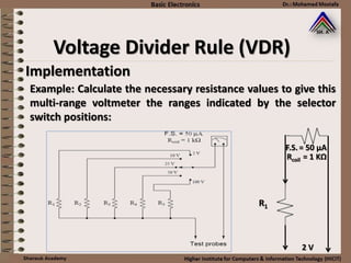
![Implementation
For voltage range 2 V:
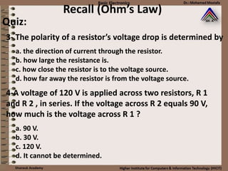
Maximum volt measured by the meter = Vcoil
Vcoil = Rcoil * F.S. = [1*(103)] * [50 *(10-6)]
= 0,05 V
VR1 = input volt range – Vcoil
= 2 – 0.05 = 1.95 V
R1 = VR1 /I
= 1.95 V / F.S. = 1.95/50*10-6 = 39 KΩ
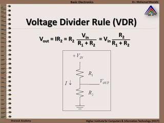
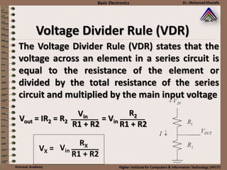
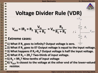
Voltage Divider Rule (VDR)](https://image.slidesharecdn.com/2-ohms-law-160215051701/85/2-ohms-law-32-320.jpg)
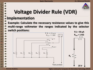
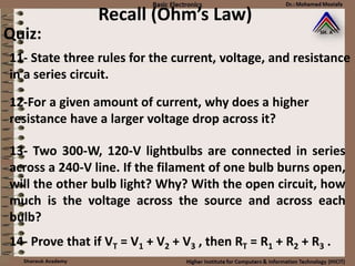
![Implementation
For voltage range 25 V:
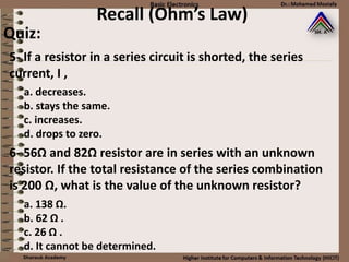
Maximum volt measured by the meter = Vcoil
Vcoil = Rcoil * F.S. = [1*(103)] * [50 *(10-6)]
= 0,05 V
VR1 = input volt range – Vcoil
= 25 – 0.05 = 24.95 V
R1 = VR1 /I
= 24.95 V / F.S. = 24.95/50*10-6 = 500 KΩ
Voltage Divider Rule (VDR)](https://image.slidesharecdn.com/2-ohms-law-160215051701/85/2-ohms-law-34-320.jpg)

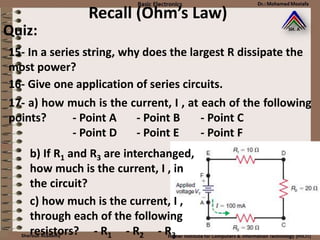
![Implementation
For voltage range 25 V:
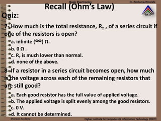
Maximum volt measured by the meter = Vcoil
Vcoil = Rcoil * F.S. = [1*(103)] * [50 *(10-6)]
= 0,05 V
VR1 = input volt range – Vcoil
= 100 – 0.05 = 99.95 V
R1 = VR1 /I
= 99.95 V / F.S. = 99.95/50*10-6 = 2 mΩ
Voltage Divider Rule (VDR)](https://image.slidesharecdn.com/2-ohms-law-160215051701/85/2-ohms-law-36-320.jpg)
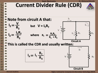
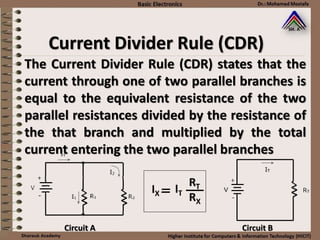
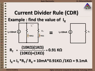
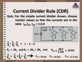
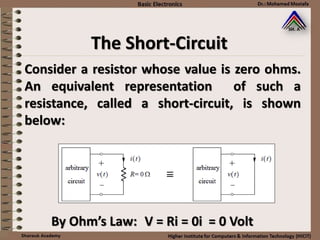
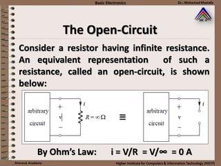
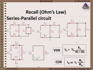
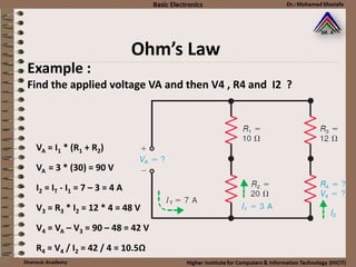


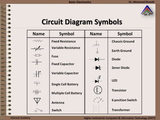
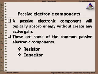
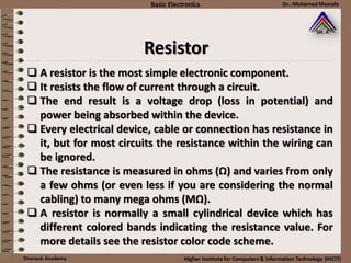
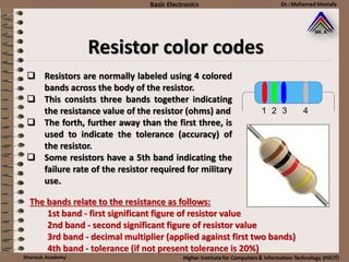
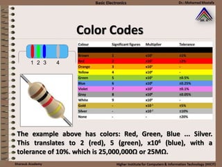
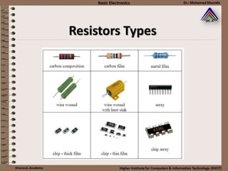
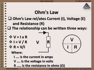
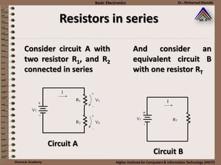
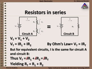
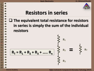
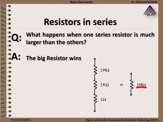
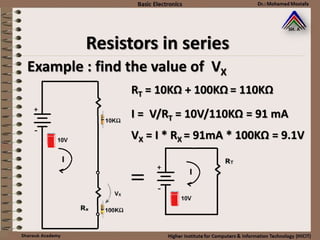
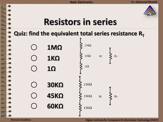
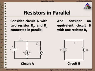
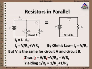
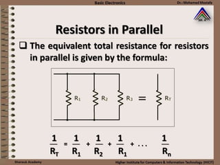
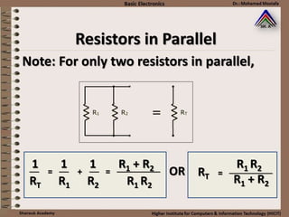
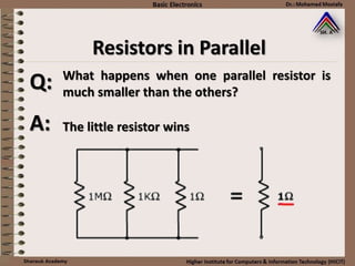
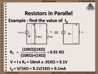
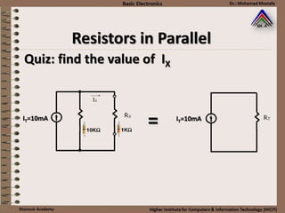
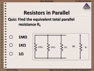
This document provides information about basic circuit diagram symbols and components. It begins with an overview of basic circuit diagrams showing a power source, switch, and load. It then discusses passive electronic components like resistors and capacitors. Resistors are described in detail, including color codes, types, and how resistors behave in series and parallel circuits. Ohm's law and applications like voltage dividers and current dividers are also covered.


