This document is from a KS3 Physics textbook. It provides information on electrical circuits, including introducing series and parallel circuits. Key points covered include:
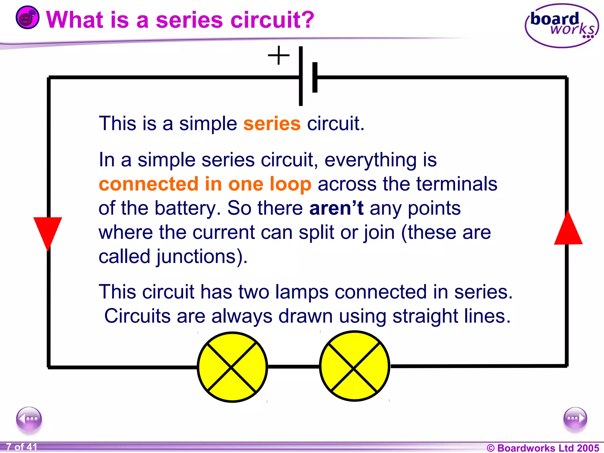
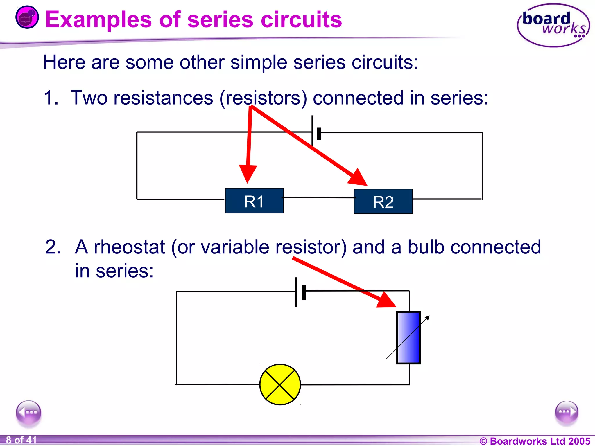
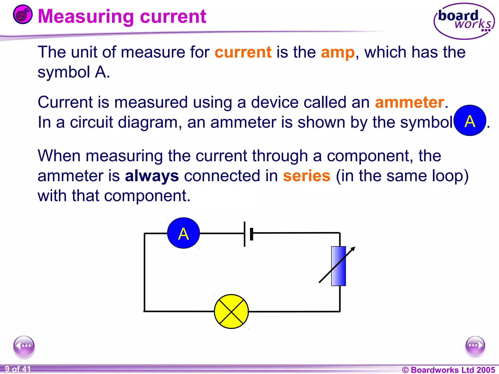
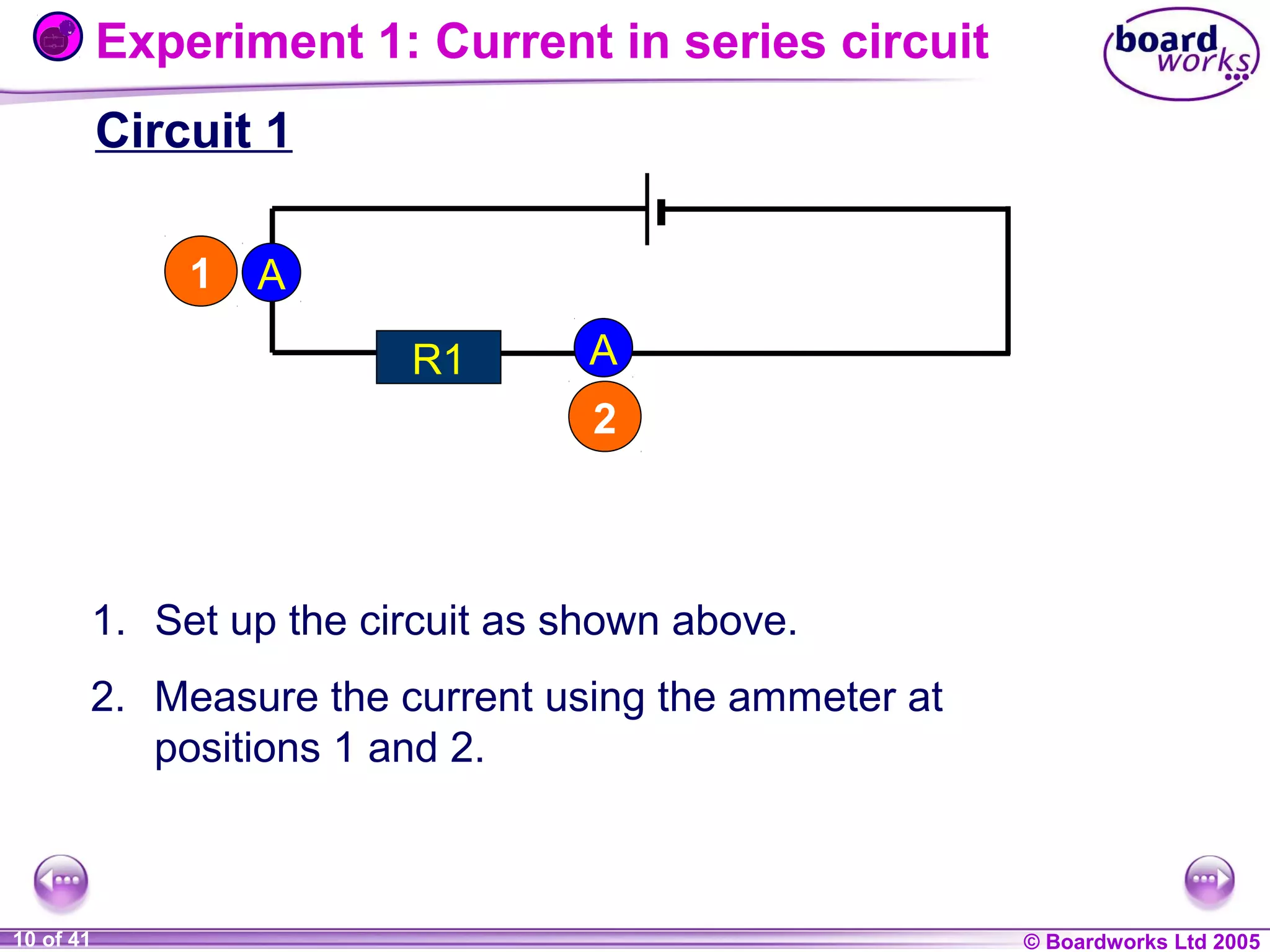
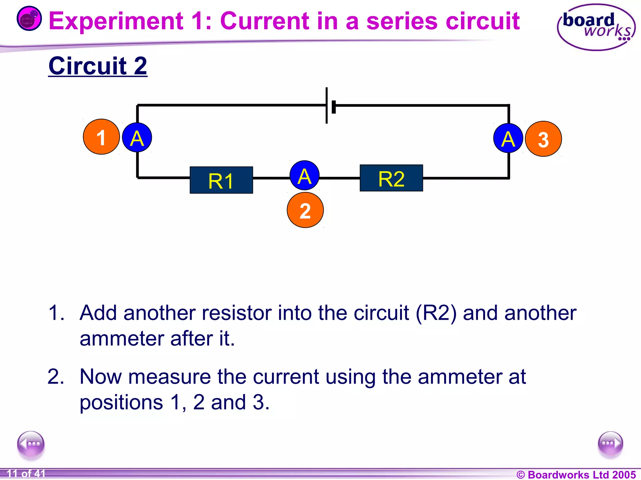
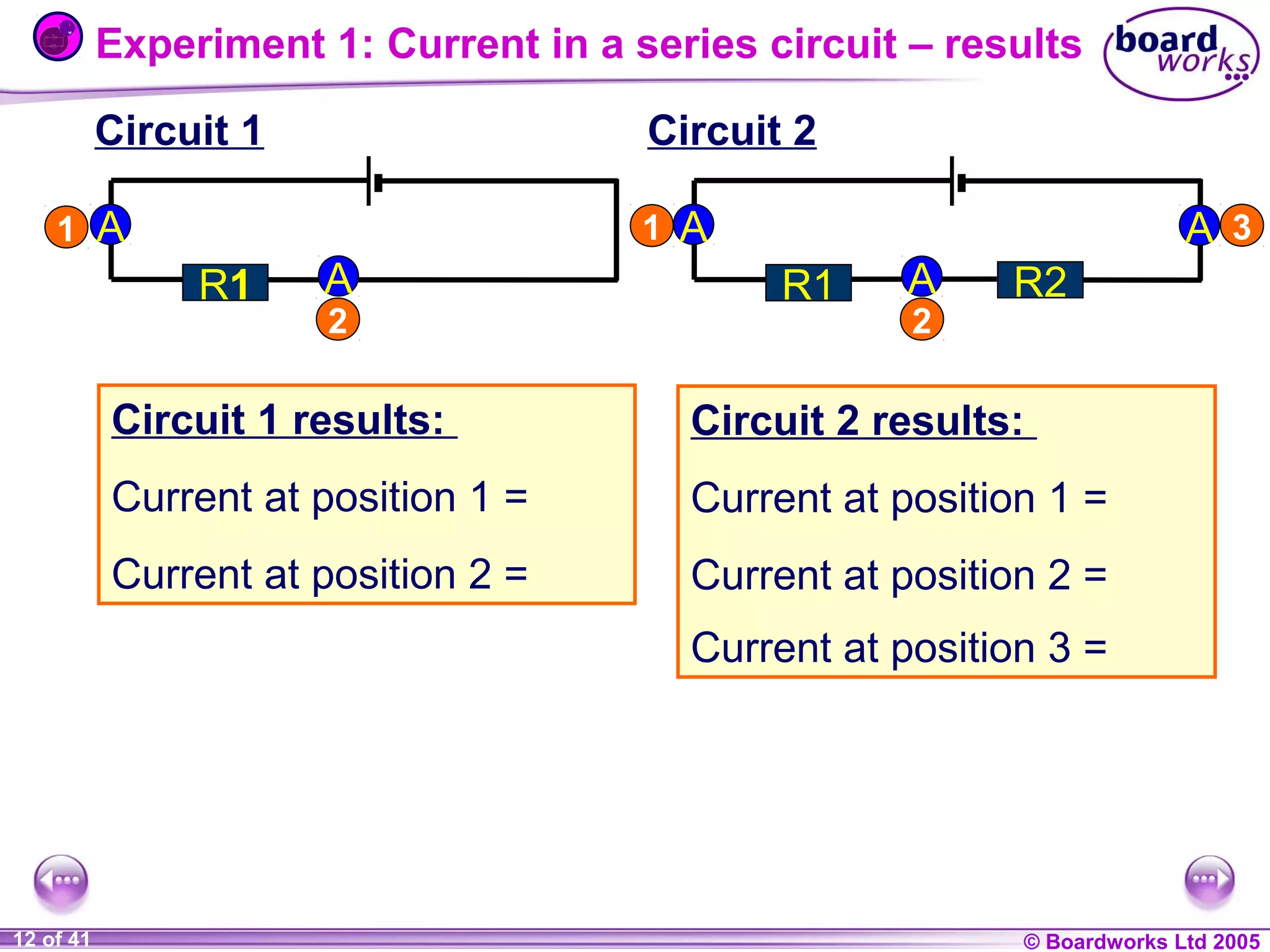
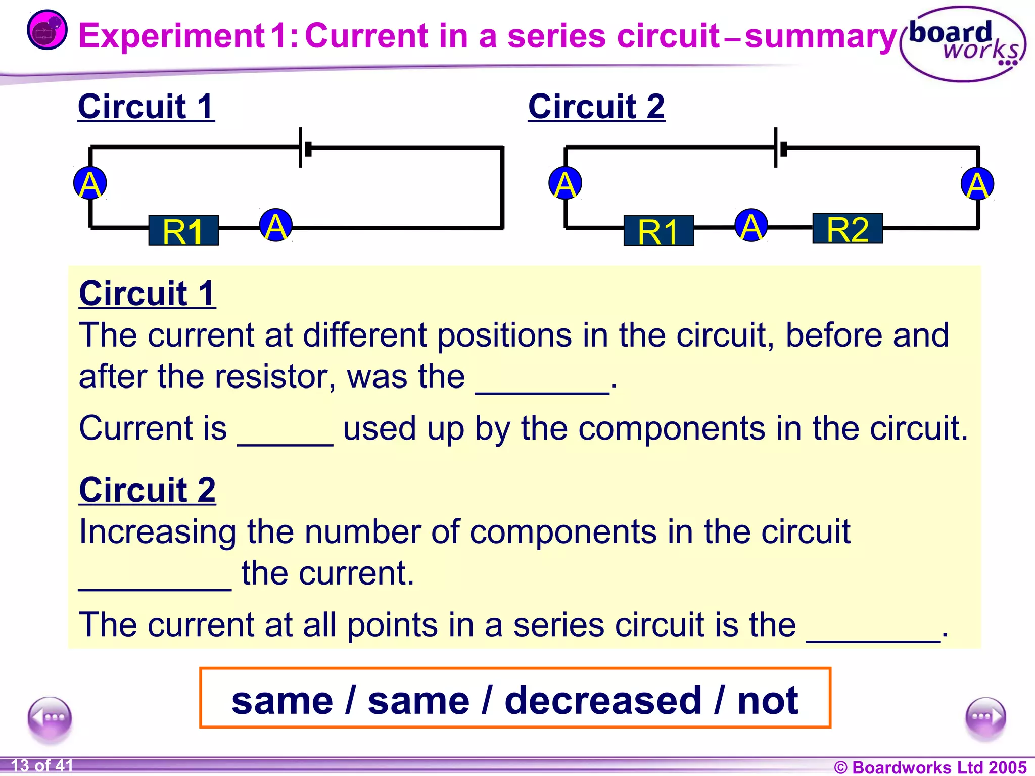
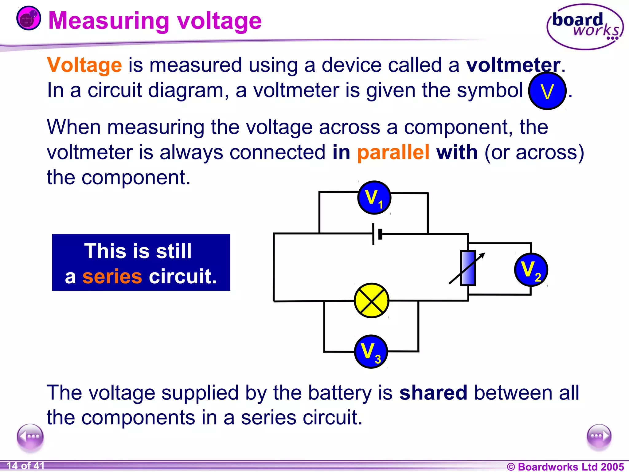
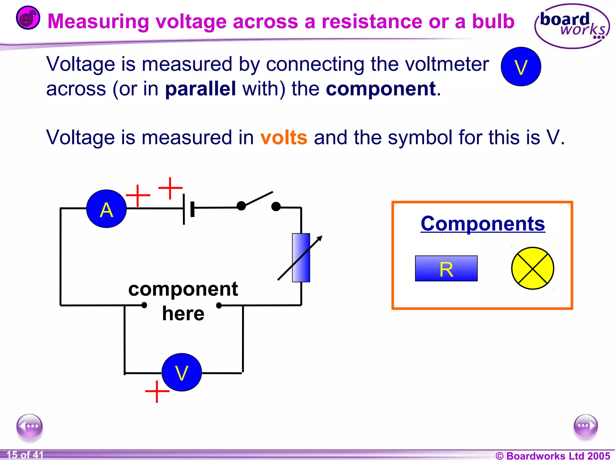
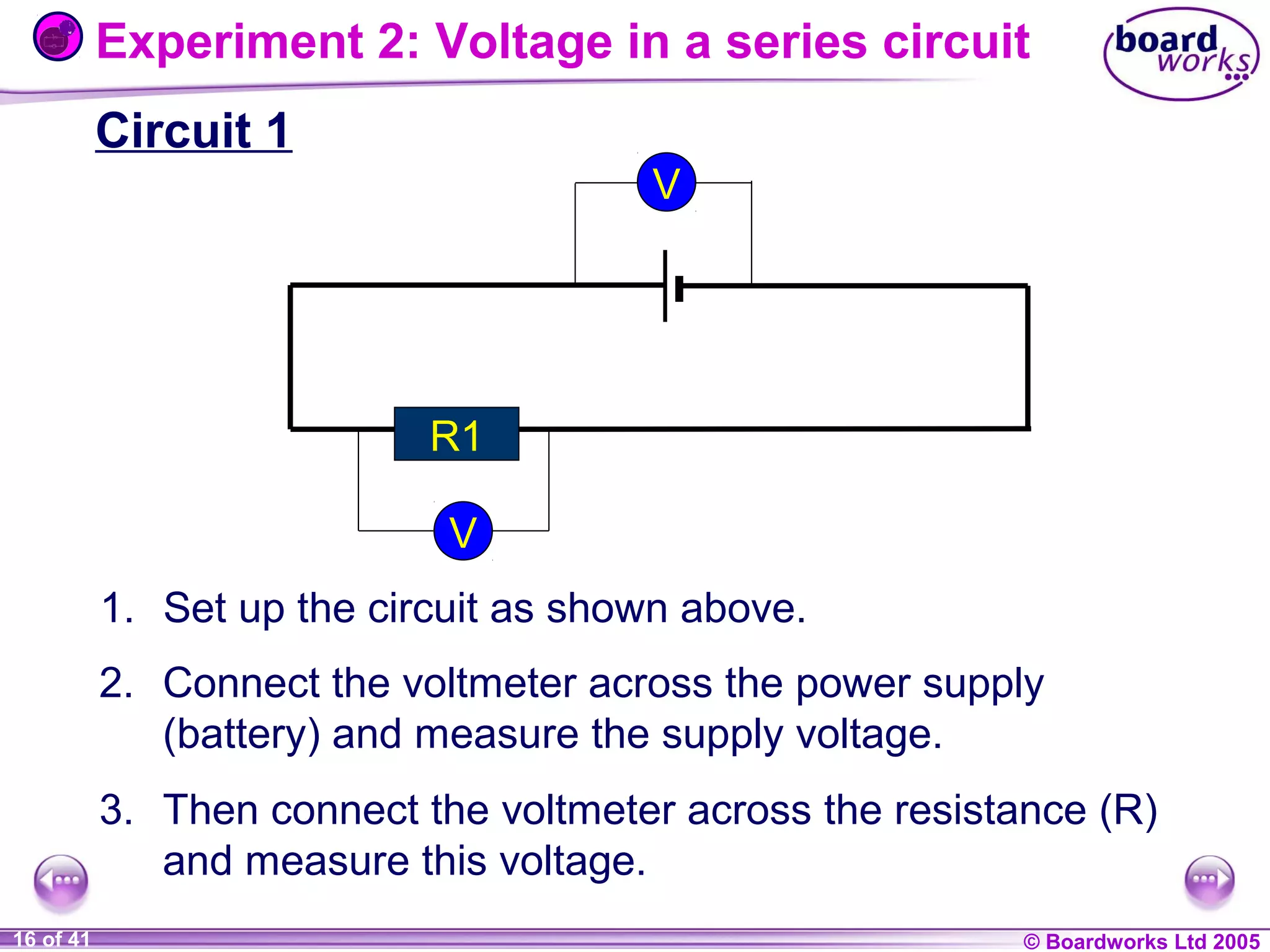
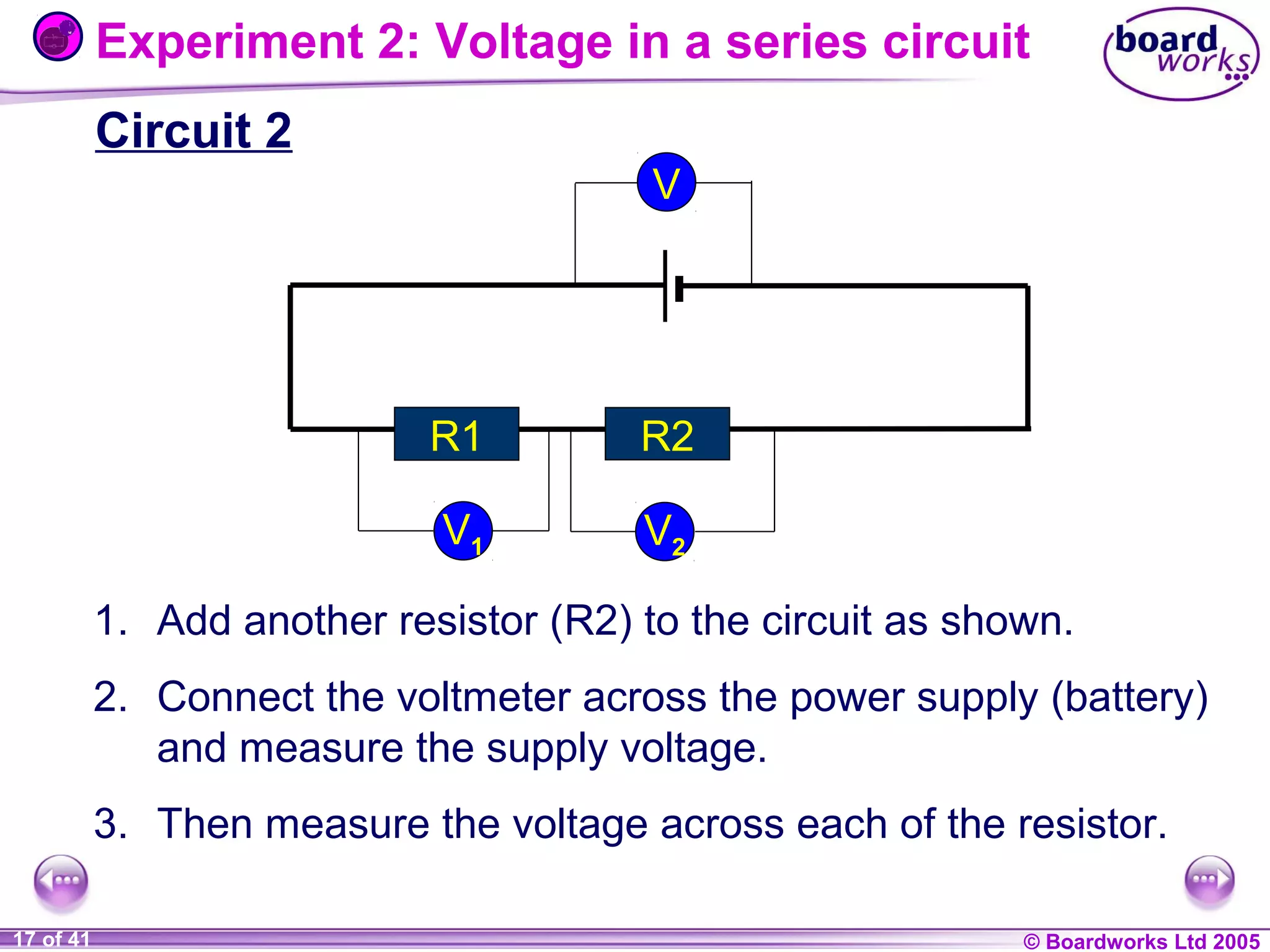
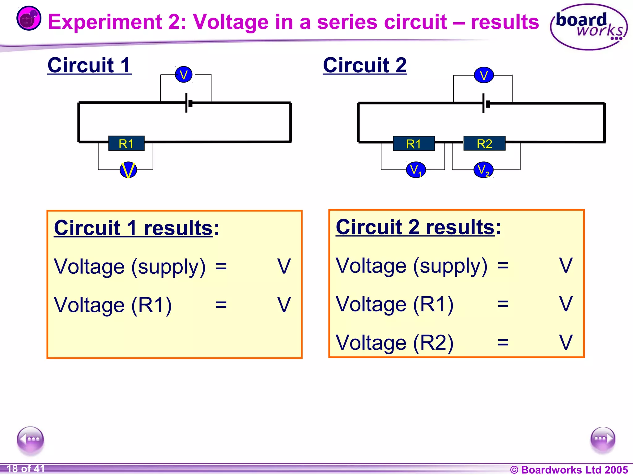
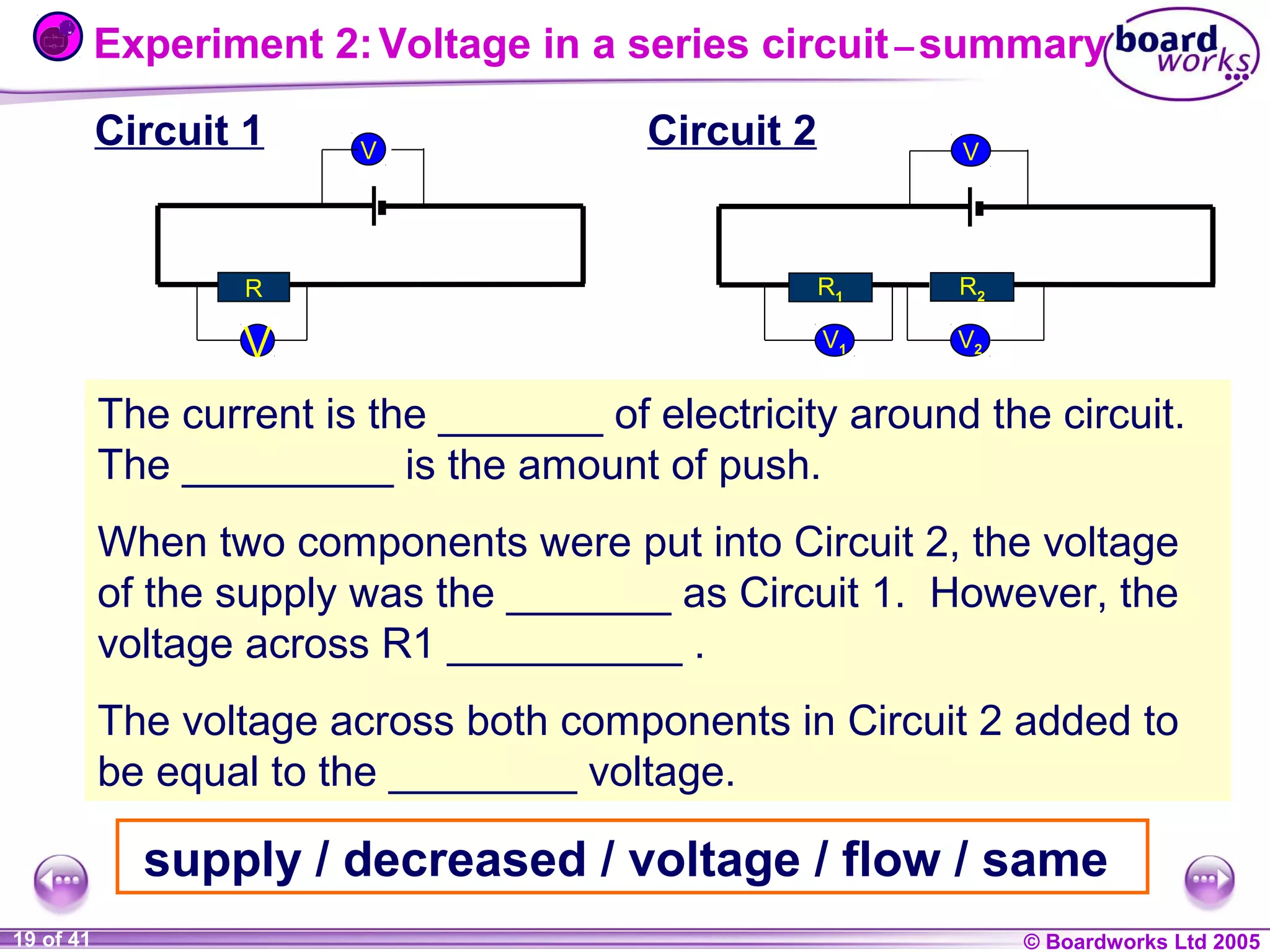
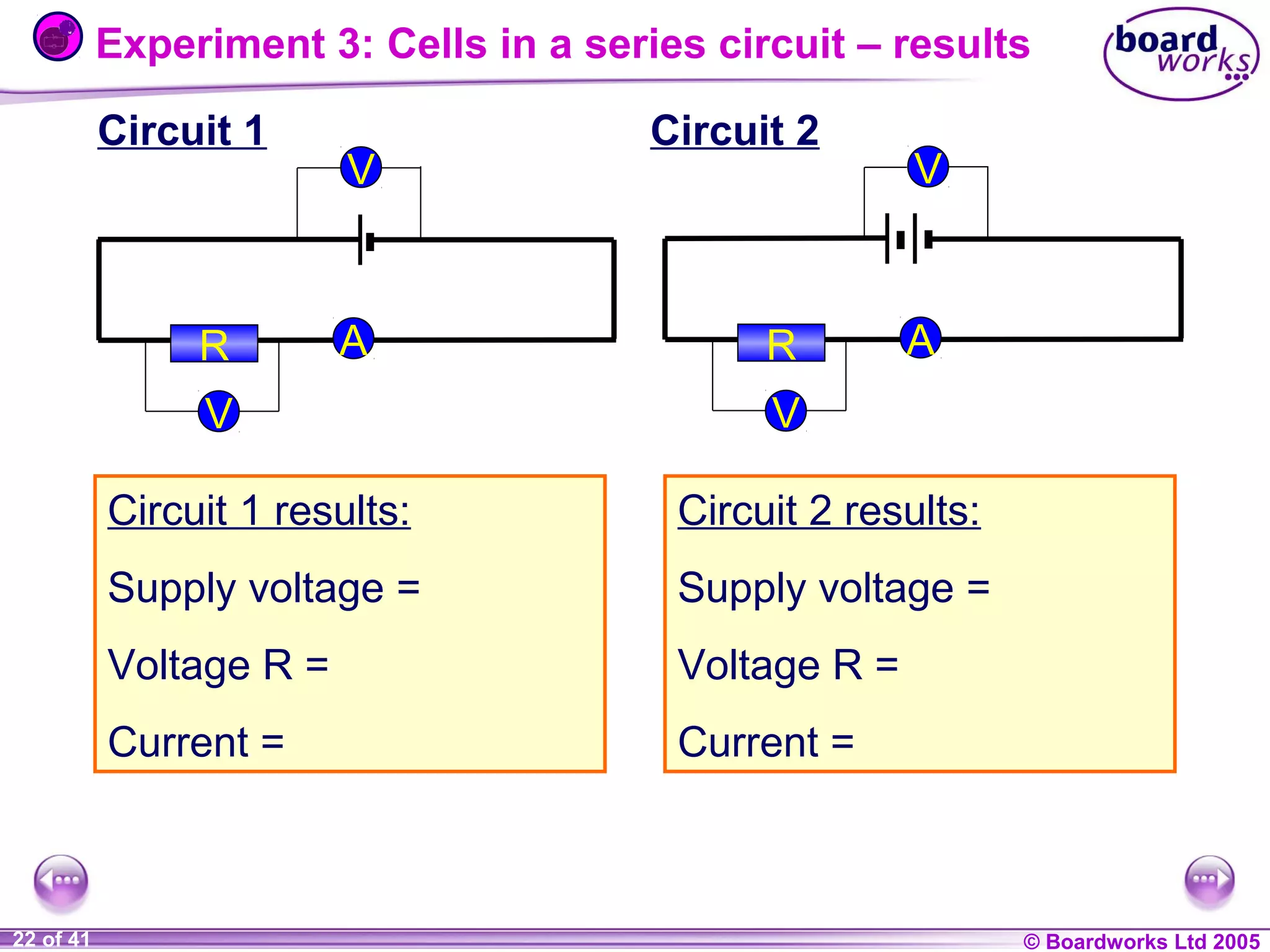
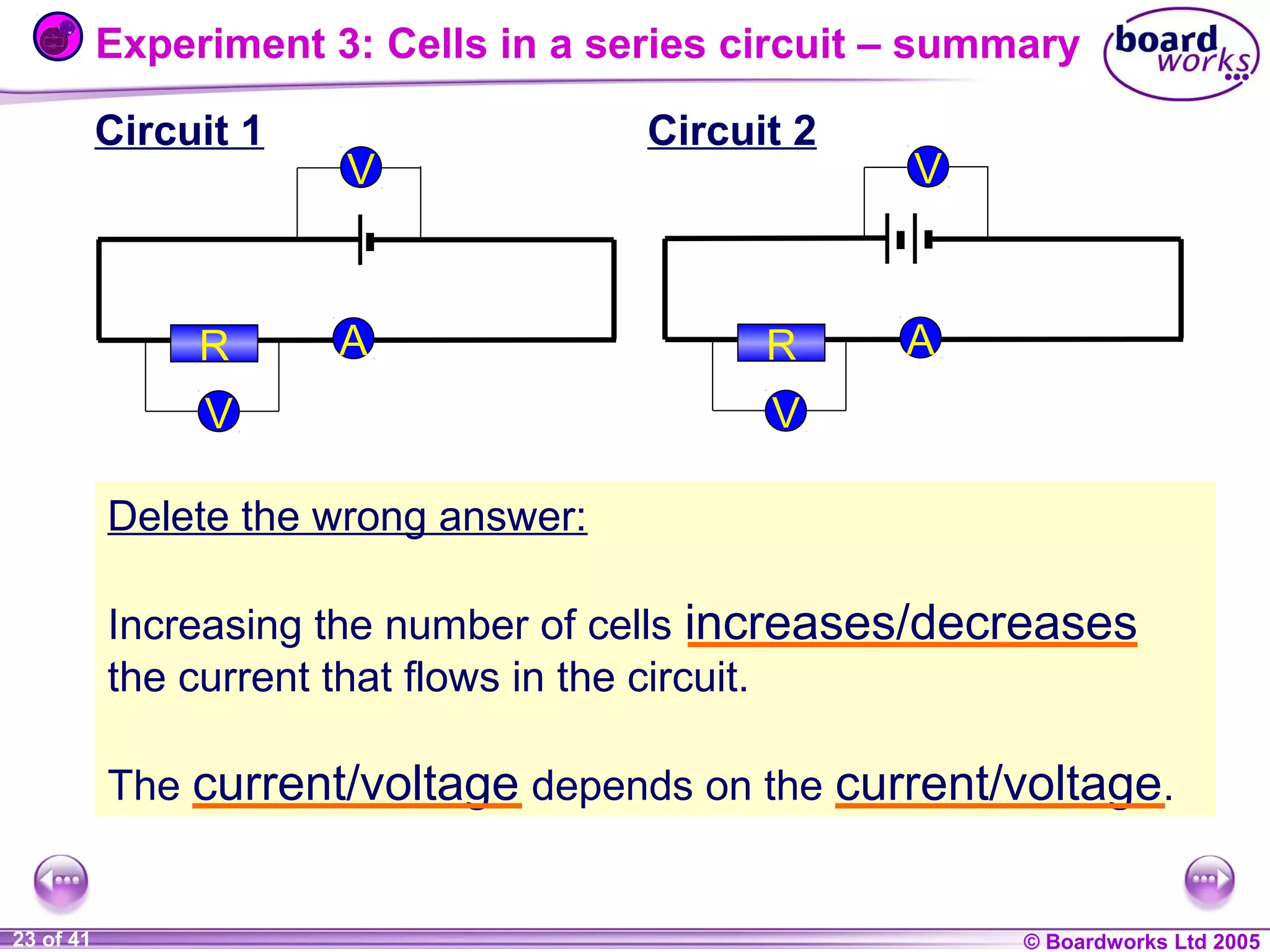
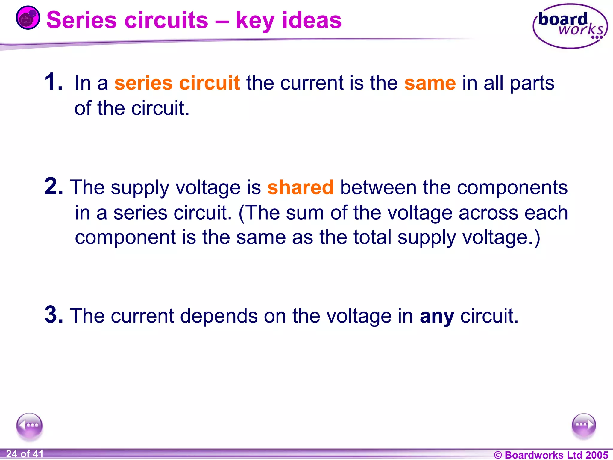
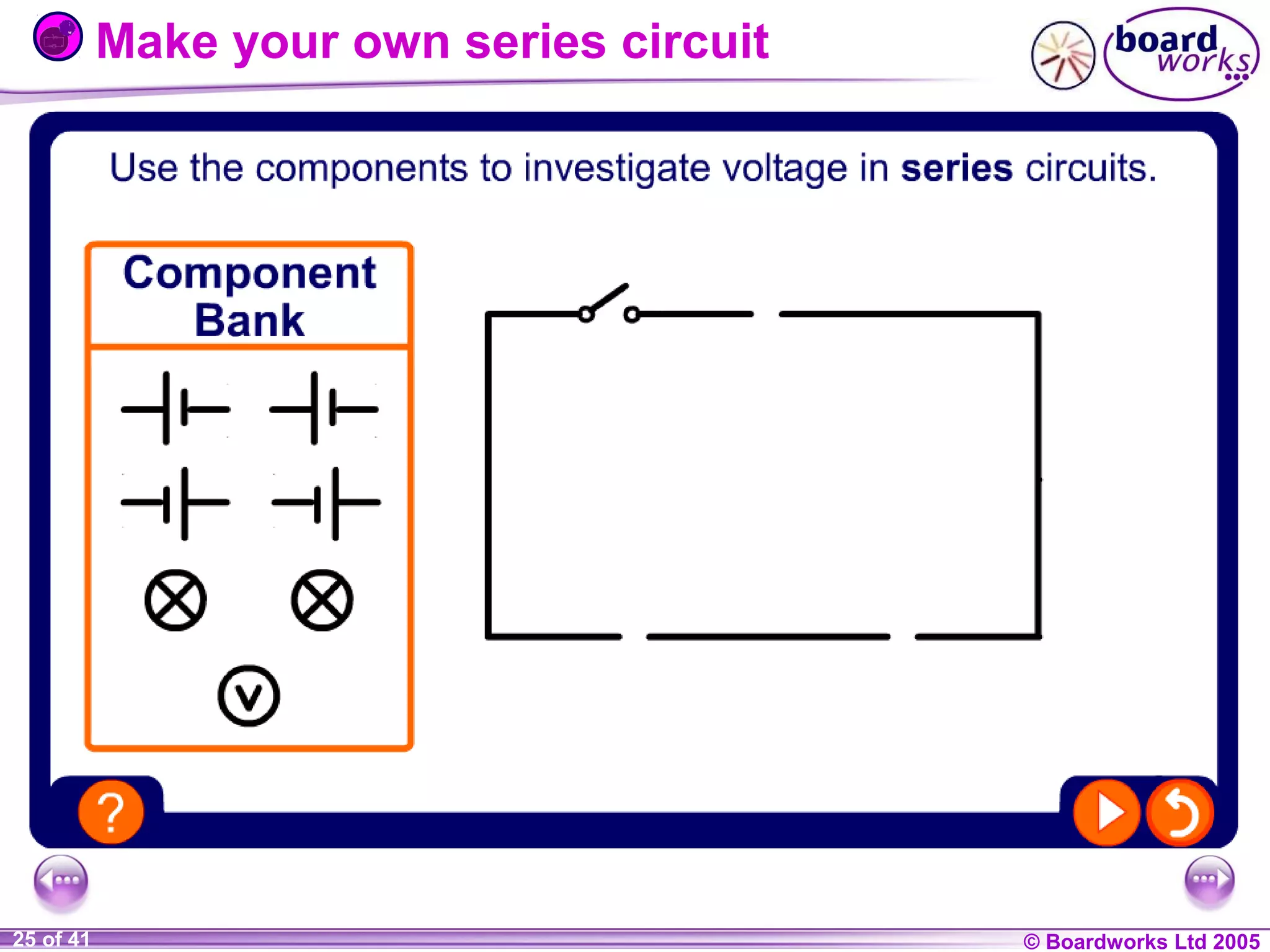
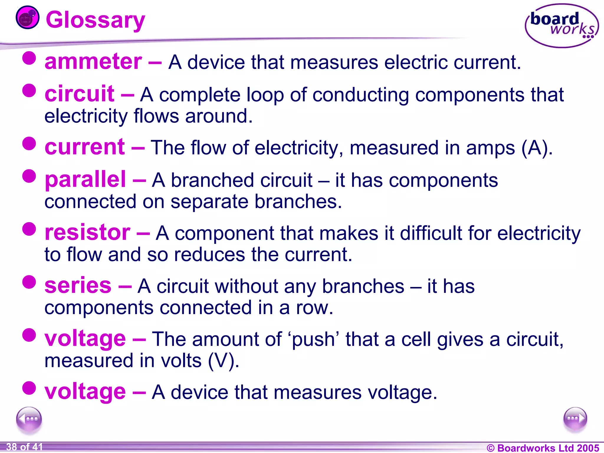
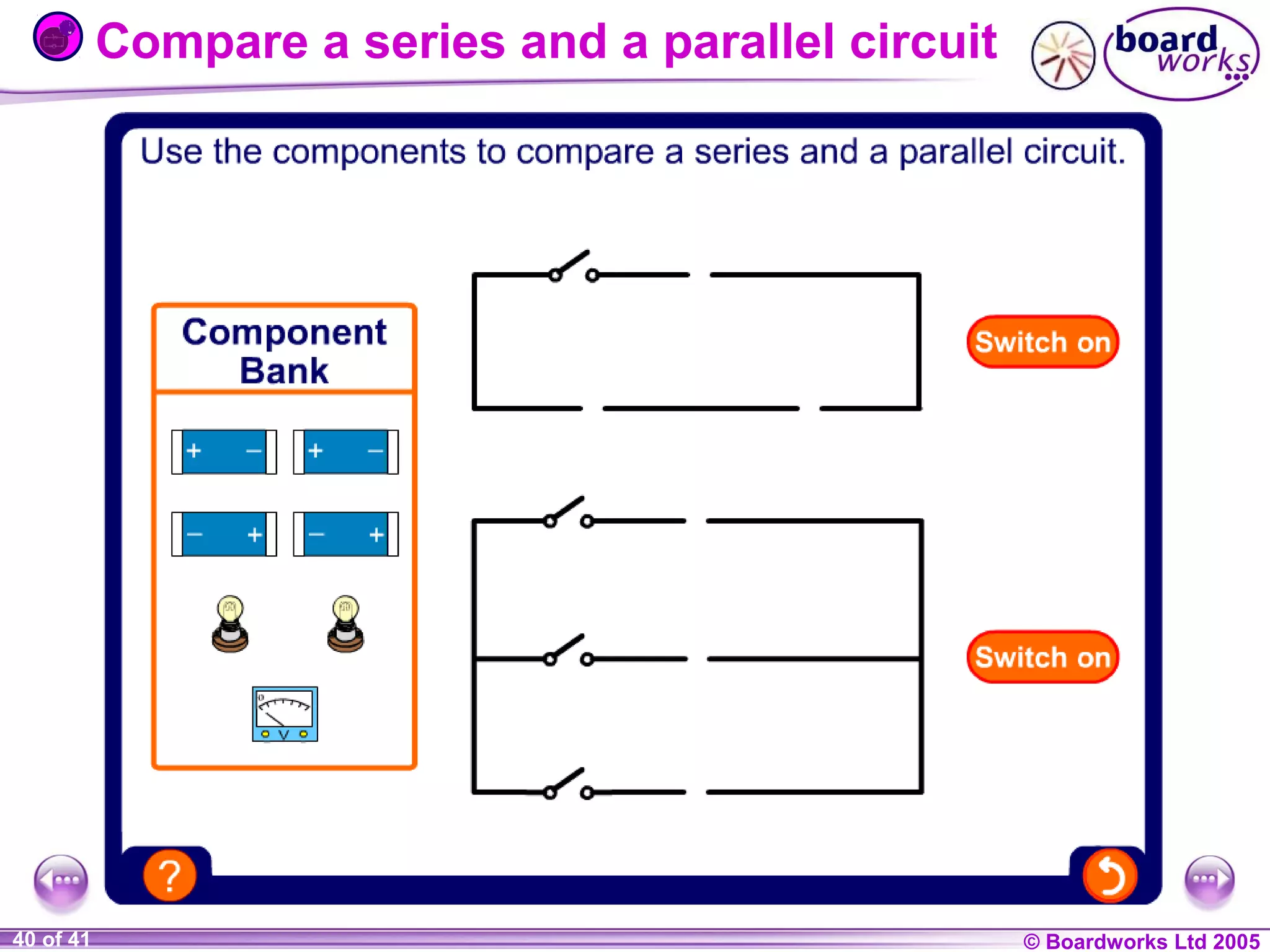
- Series circuits have components connected in a single loop so the current is the same throughout. The voltage splits between components.
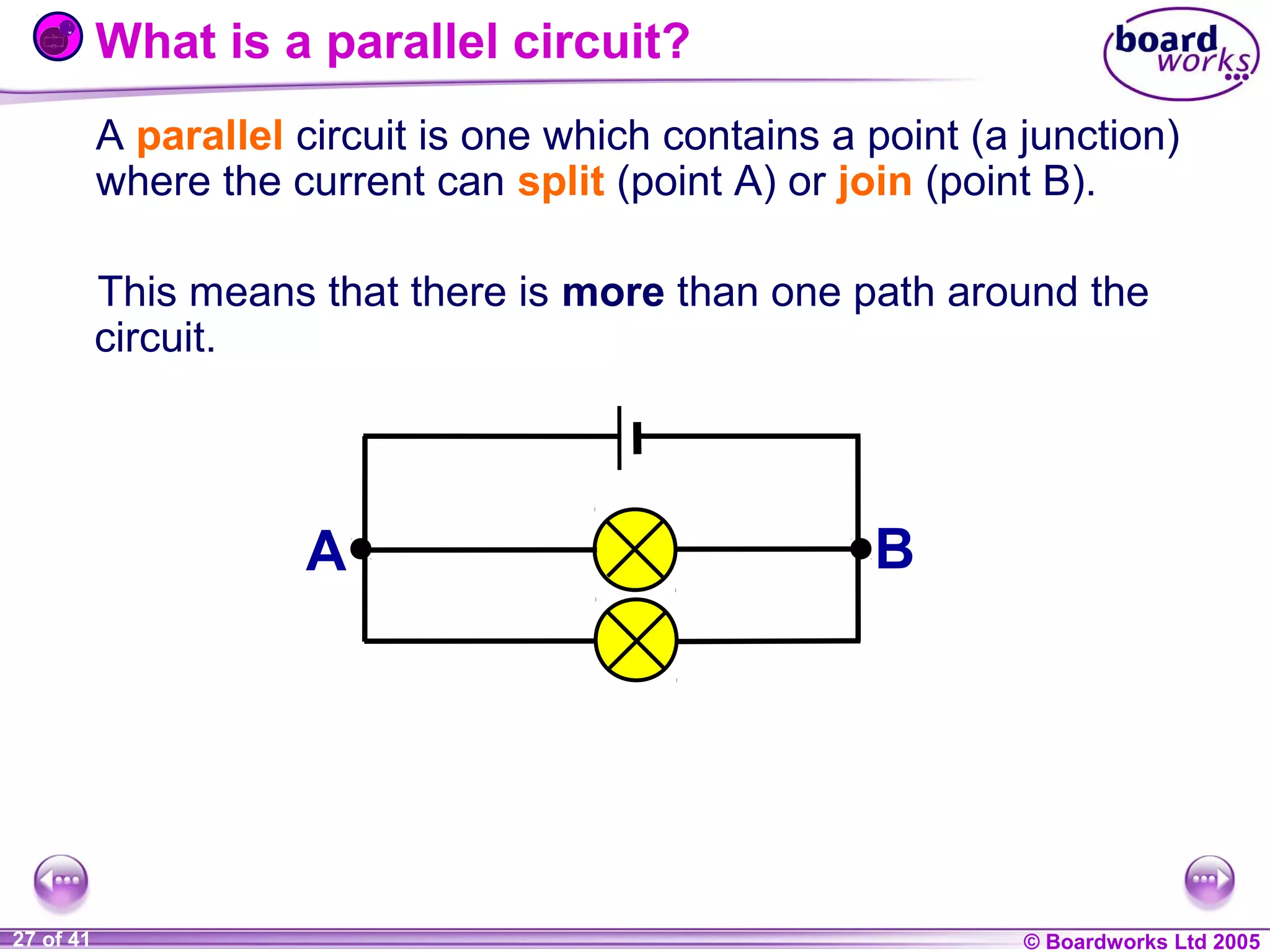
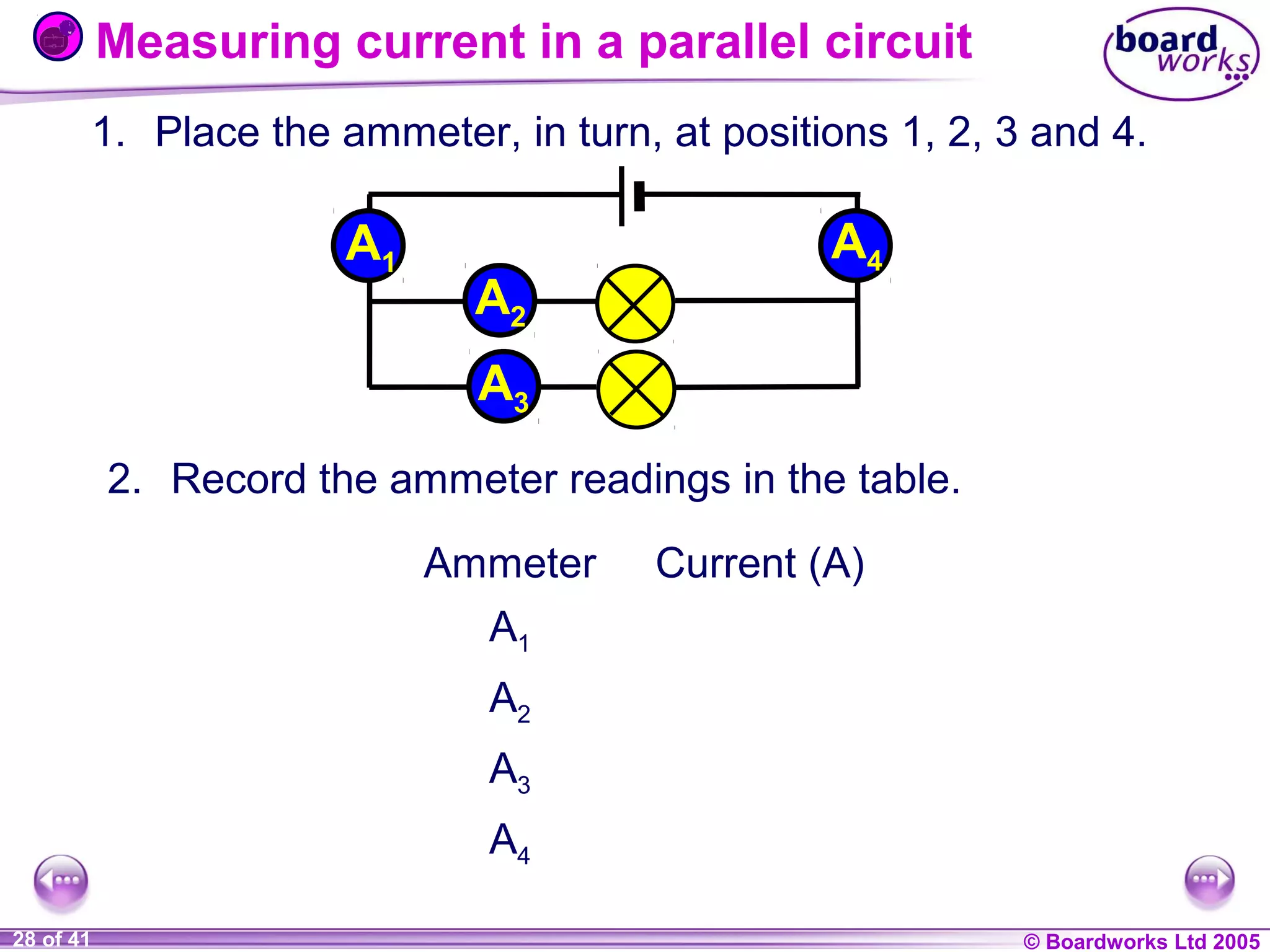
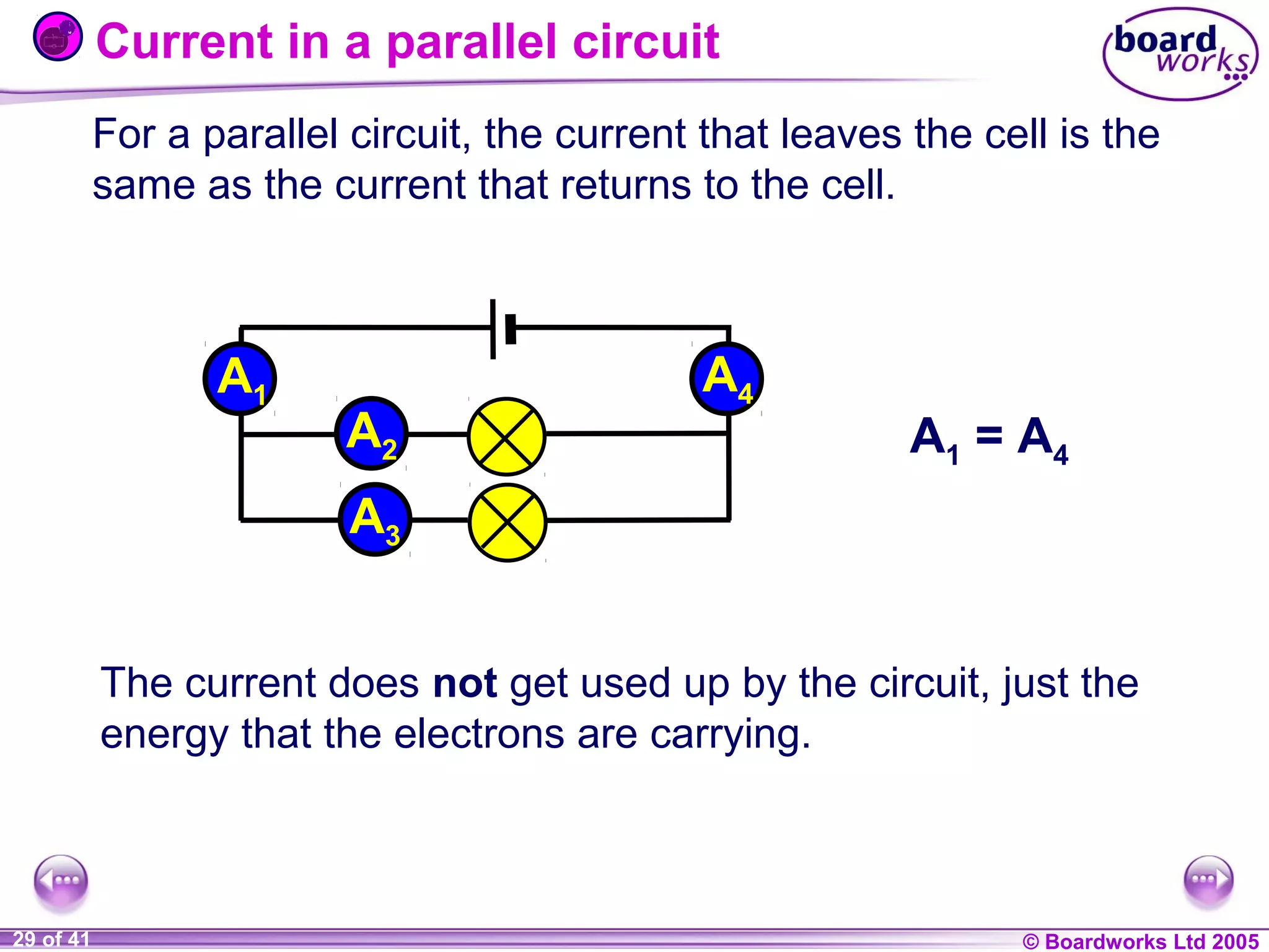
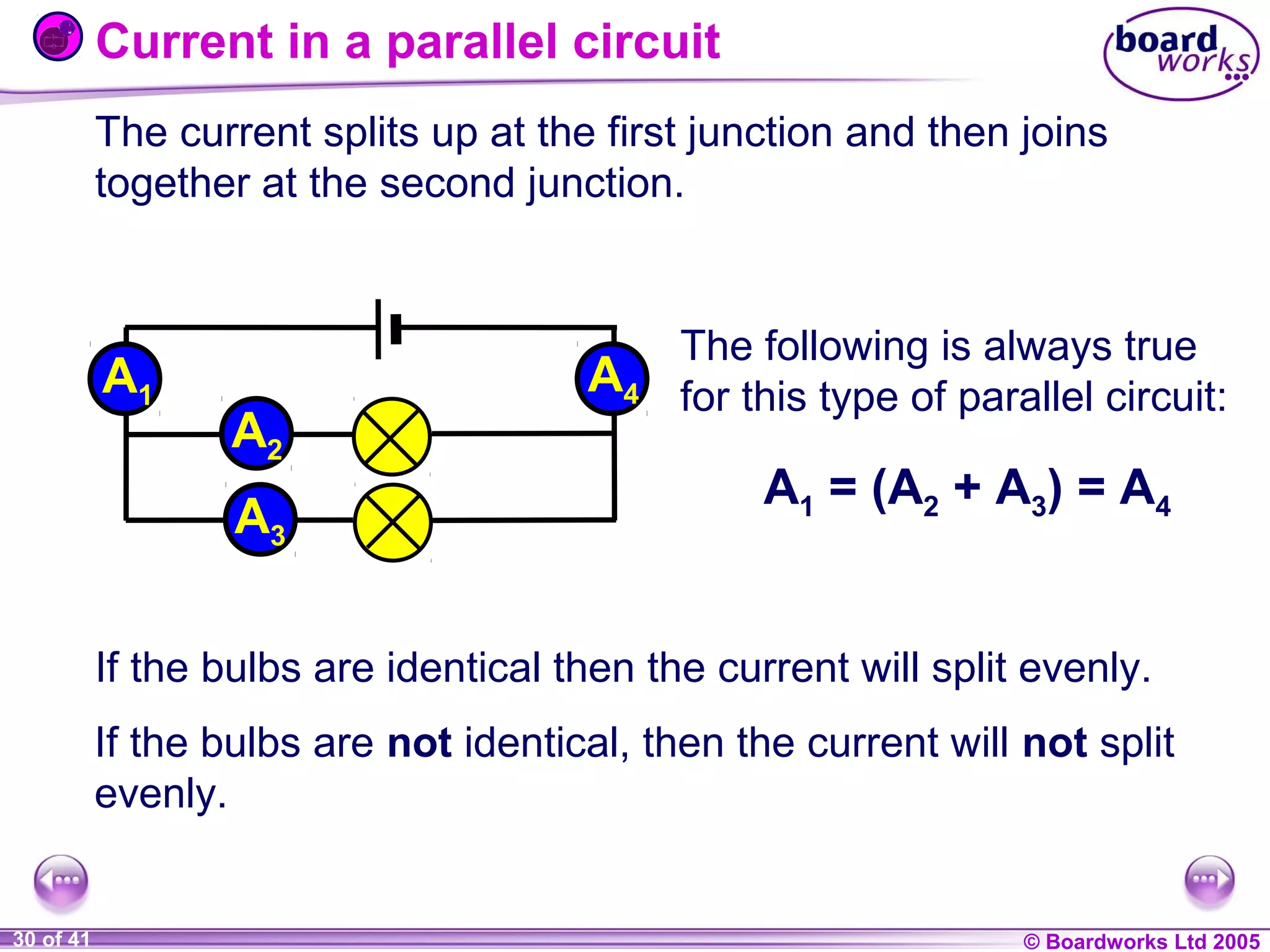
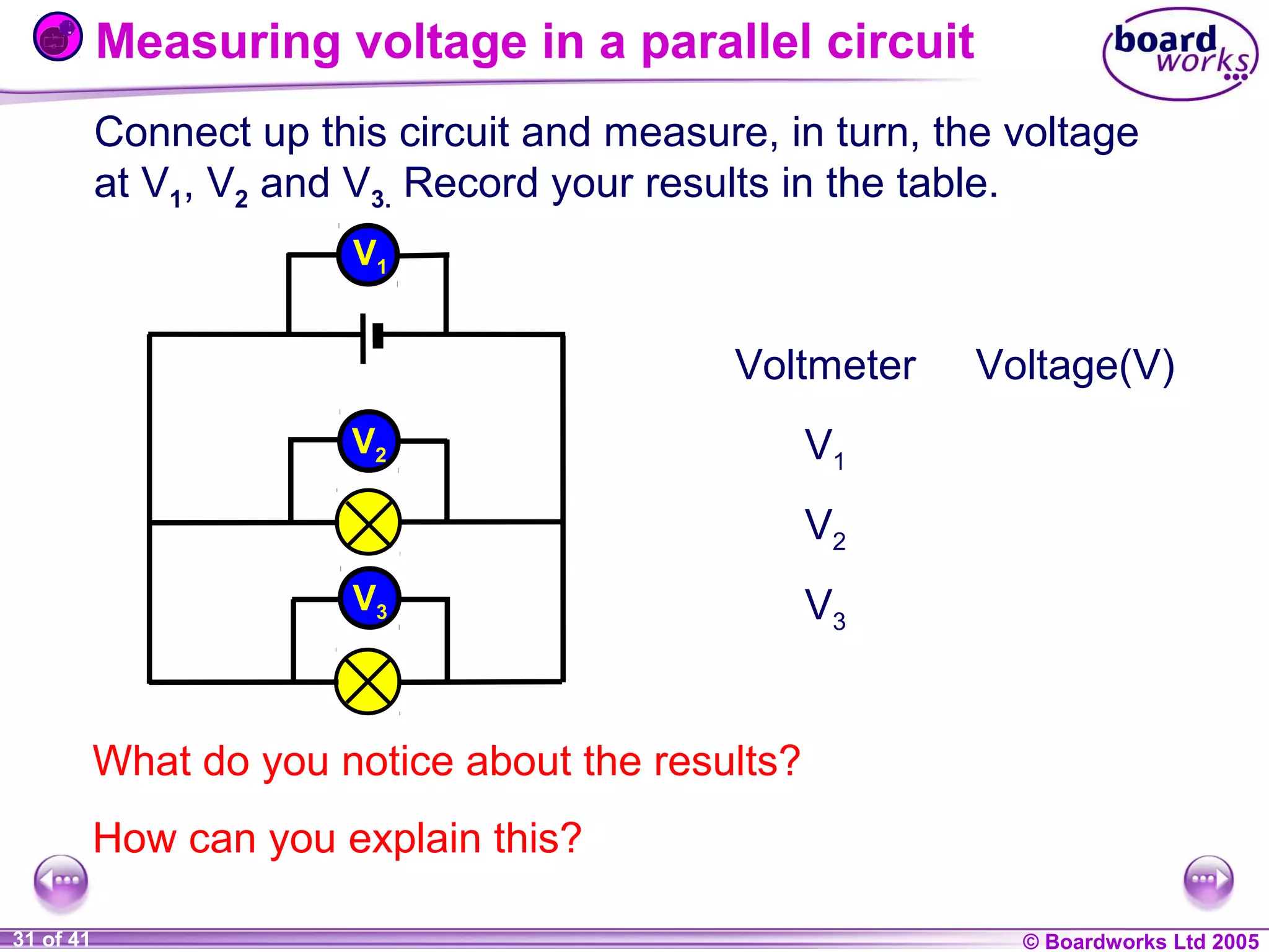
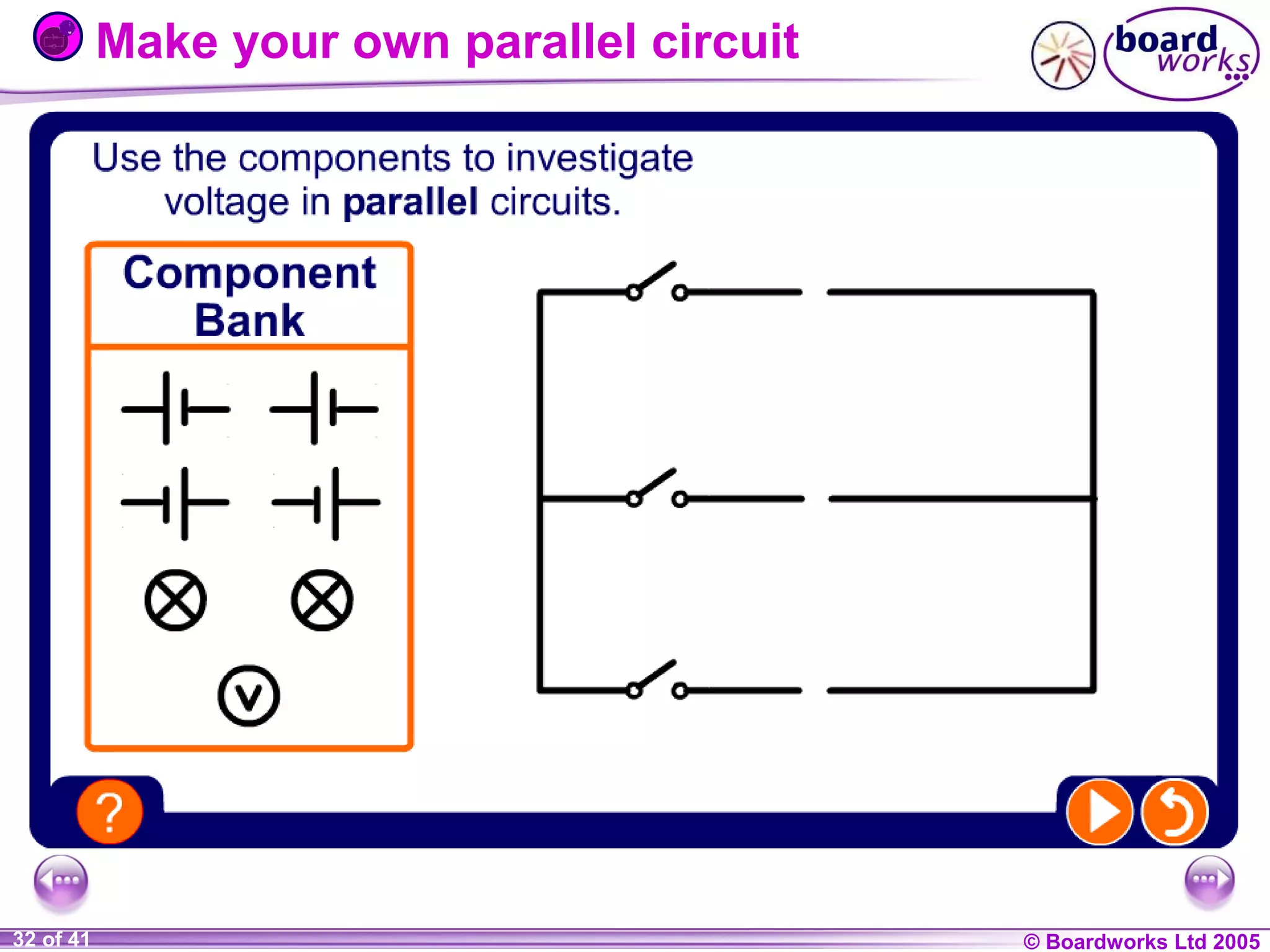
- Parallel circuits have multiple paths so the current can split and join at junctions. The voltage is the same across each part.
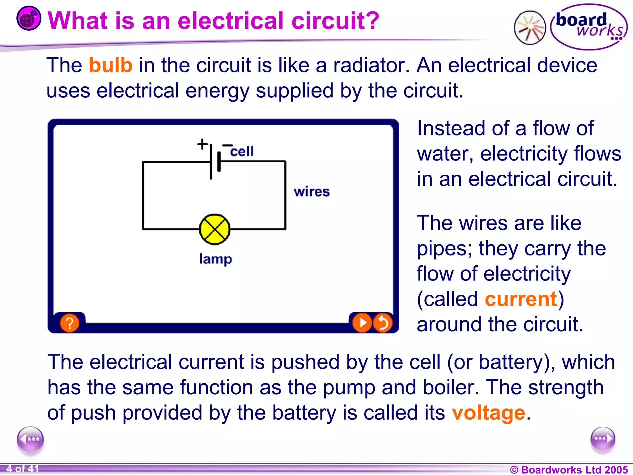
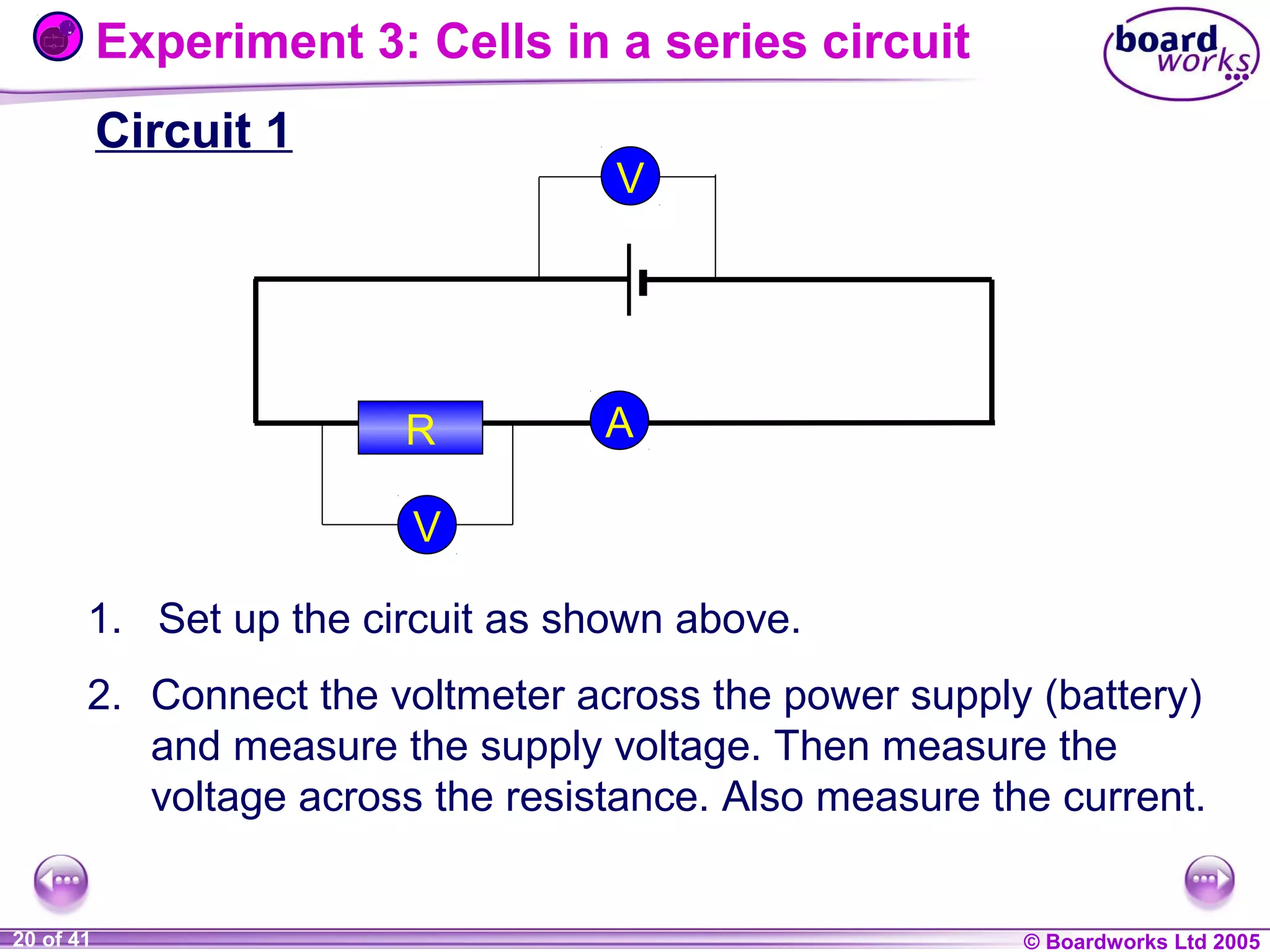
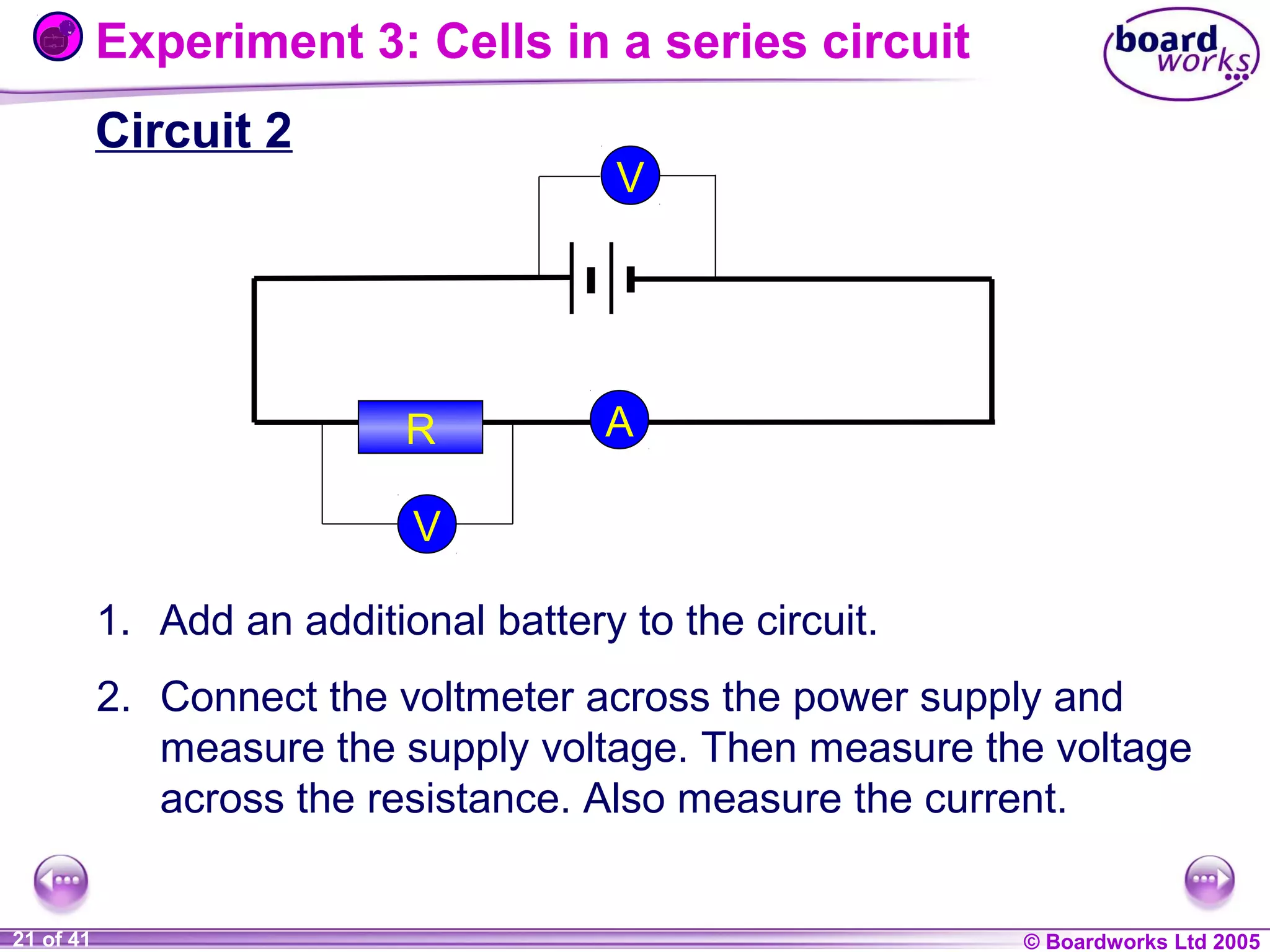
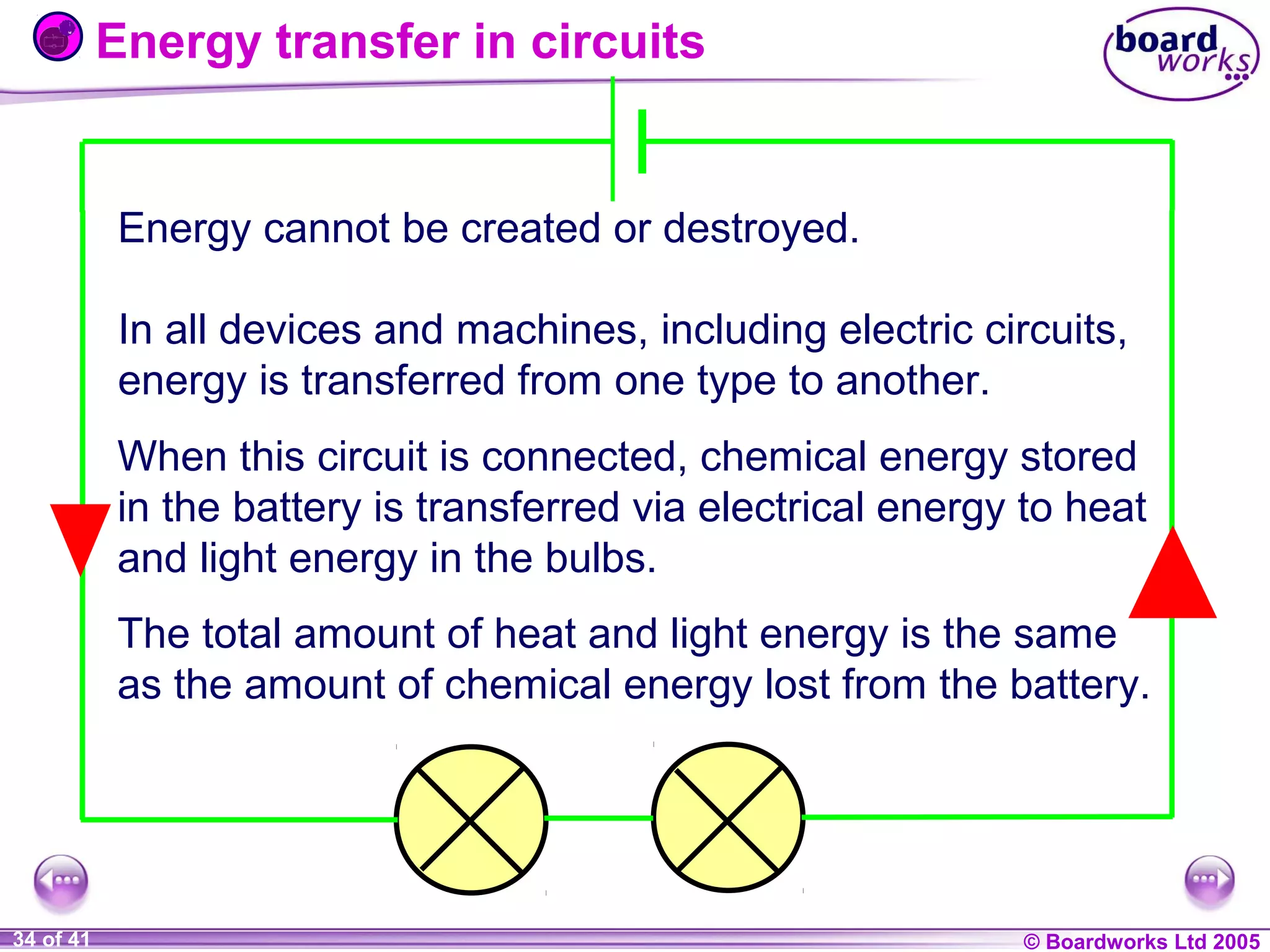
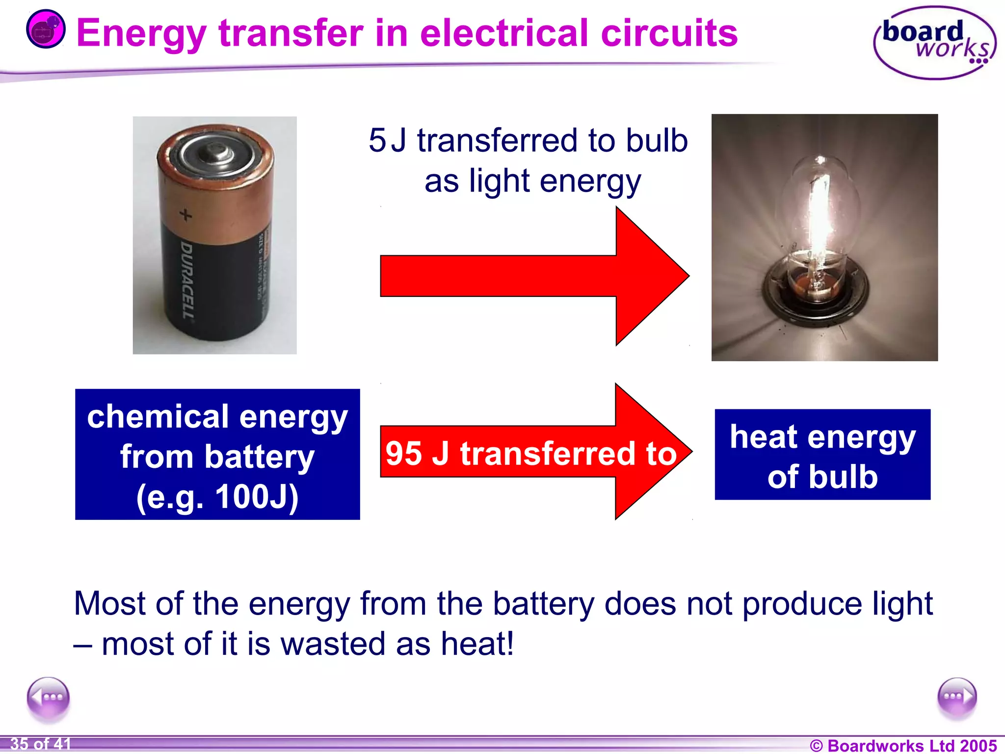
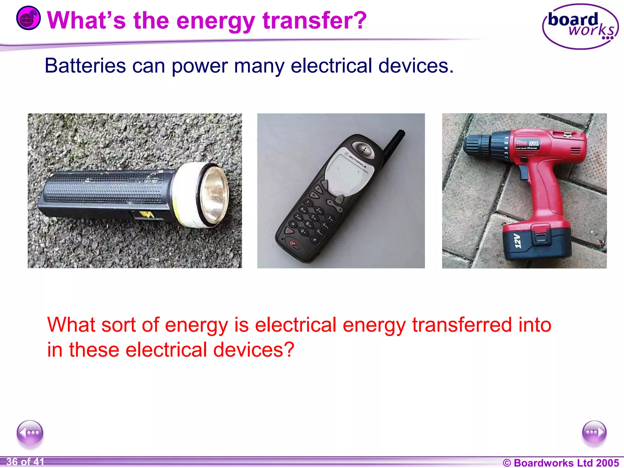
- Energy from batteries is transferred through electrical circuits and converted to other forms like light and heat in bulbs. The total energy transferred equals the chemical energy lost from the battery.


![Coded Agents – with UiPath SDK + LangGraph [Virtual Hands-on Workshop]](https://cdn.slidesharecdn.com/ss_thumbnails/codedagentsdeck-251215155422-5497c599-thumbnail.jpg?width=640&height=640&fit=bounds)

