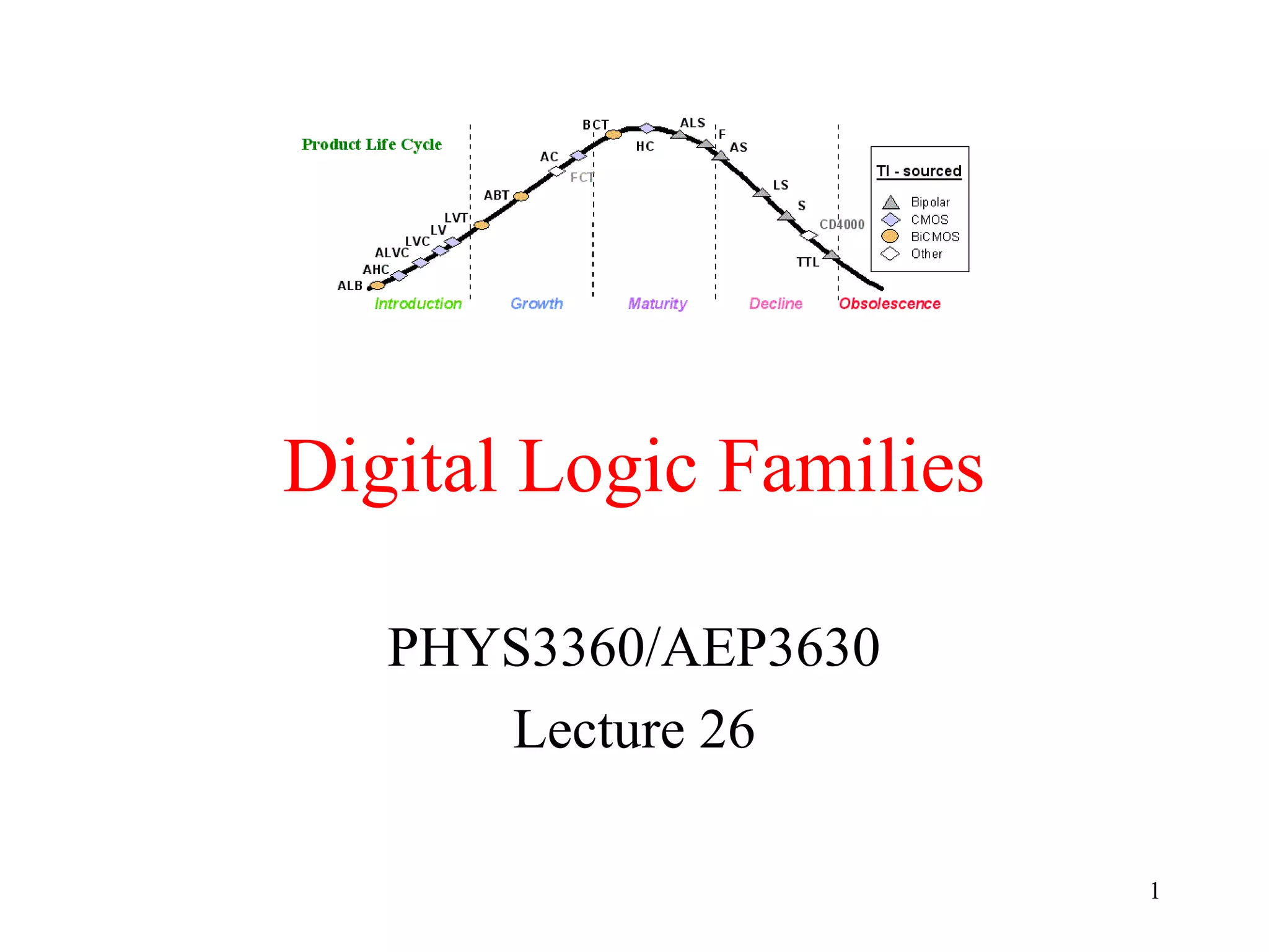
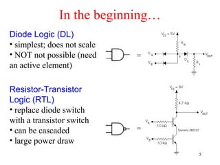
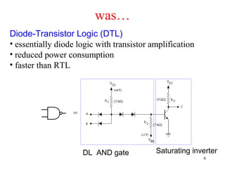
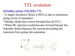
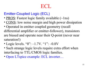
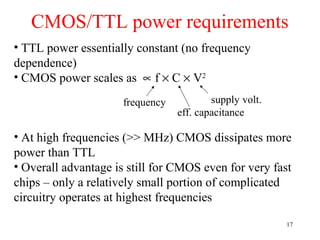
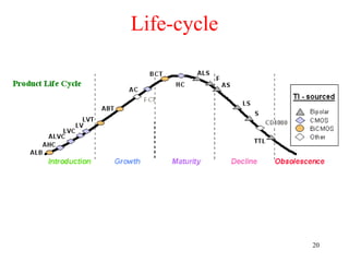
Digital Logic Families
PHYS3360/AEP3630
Lecture 26
1
Overview
• Integration, Moore’s law
• Early families (DL, RTL)
• TTL
• Evolution of TTL family
• ECL
• CMOS family and its evolution
• Overview
2
Integration Levels
• Gate/transistor ratio is roughly 1/10
– SSI < 12 gates/chip
– MSI < 100 gates/chip
– LSI …1K gates/chip
– VLSI …10K gates/chip
– ULSI …100K gates/chip
– GSI …1Meg gates/chip
3
Moore’s law
• A prediction made by Moore (a co-founder of Intel) in
1965: “… a number of transistors to double every 2
years.”
4
In the beginning…
Diode Logic (DL)
• simplest; does not scale
• NOT not possible (need
an active element)
=
=
Resistor-Transistor
Logic (RTL)
• replace diode switch
with a transistor switch
• can be cascaded
• large power draw
5
was…
=
Diode-Transistor Logic (DTL)
• essentially diode logic with transistor amplification
• reduced power consumption
• faster than RTL
DL AND gate Saturating inverter
6
VOH(min) – The minimum voltage level at an output in the logical
“1” state under defined load conditions
VOL(max) – The maximum voltage level at an output in the logical
“0” state under defined load conditions
VIH(min) – The minimum voltage required at an input to be
recognized as “1” logical state
VIL(max) – The maximum voltage required at an input that still will
be recognized as “0” logical state
Logic families: V levels
VOH VIH VOL VIL
7
IOH – Current flowing into an output in the logical “1” state under
specified load conditions
IOL – Current flowing into an output in the logical “0” state under
specified load conditions
IIH – Current flowing into an input when a specified HI level is
applied to that input
IIL – Current flowing into an input when a specified LO level is
applied to that input
Logic families: I requirements
VOH VIH VOL VIL
IOH IIH IOL IIL
8
Fanout: the maximum number of logic inputs (of the same
logic family) that an output can drive reliably
Logic families: fanout
DC fanout = min( )
IL
OL
IH
OH
I
I
I
I
,
9
Logic families: propagation delay
TPD,HL TPD,LH
TPD,HL – input-to-output propagation delay from HI to LO output
TPD,LH – input-to-output propagation delay from LO to HI output
Speed-power product: TPD × Pavg
10
Logic families: noise margin
VNH
VNL
HI state noise margin:
VNH = VOH(min) – VIH(min)
LO state noise margin:
VNL = VIL(max) – VOL(max)
Noise margin:
VN = min(VNH,VNL)
11
TTL
2-input NAND
Bipolar Transistor-Transistor Logic (TTL)
• first introduced by in 1964 (Texas Instruments)
• TTL has shaped digital technology in many ways
• Standard TTL family (e.g. 7400) is obsolete
• Newer TTL families still
used (e.g. 74ALS00)
Distinct features
• Multi-emitter transistors
• Totem-pole transistor
arrangement
• Open LTspice example:
TTL NAND… 12
TTL evolution
Schottky series (74LS00) TTL
• A major slowdown factor in BJTs is due to transistors
going in/out of saturation
• Shottky diode has a lower forward bias (0.25V)
• When BC junction would become forward biased, the
Schottky diode bypasses the current preventing the
transistor from going into saturation
13
TTL family evolution
Legacy: don’t use
in new designs
Widely used today
14
ECL
Emitter-Coupled Logic (ECL)
• PROS: Fastest logic family available (~1ns)
• CONS: low noise margin and high power dissipation
• Operated in emitter coupled geometry (recall
differential amplifier or emitter-follower), transistors
are biased and operate near their Q-point (never near
saturation!)
• Logic levels. “0”: –1.7V. “1”: –0.8V
• Such strange logic levels require extra effort when
interfacing to TTL/CMOS logic families.
• Open LTspice example: ECL inverter…
15
CMOS
Complimentary MOS (CMOS)
• Other variants: NMOS, PMOS (obsolete)
• Very low static power consumption
• Scaling capabilities (large integration all MOS)
• Full swing: rail-to-rail output
• Things to watch out for:
– don’t leave inputs floating (in TTL these will float to
HI, in CMOS you get undefined behaviour)
– susceptible to electrostatic damage (finger of death)
• Open LTspice example: CMOS NOT and NAND…
16
CMOS/TTL power requirements
• TTL power essentially constant (no frequency
dependence)
• CMOS power scales as ∝ f × C × V2
• At high frequencies (>> MHz) CMOS dissipates more
power than TTL
• Overall advantage is still for CMOS even for very fast
chips – only a relatively small portion of complicated
circuitry operates at highest frequencies
frequency supply volt.
eff. capacitance
17
CMOS family evolution
obsolete
• Reduction of dynamic losses through
successively decreasing supply voltages:
12V → 5V → 3.3V → 2.5V → 1.8V
CD4000 LVC/ALVC/AVC
• Power reduction is one of the keys to
progressive growth of integration
General trend:
18
OverviewTTL
Logic
Family
CMOS
• Values typical for Vcc/Vdd = 5V
• When interfacing different families, pay attention
to their input/output voltage, current (fanout) specs.
TPD Trise/fall VIH,min VIL,max VOH,min VOL,max
Noise
Margin
19
Life-cycle
20

Logic families

  • 1.
  • 2.
    Overview • Integration, Moore’slaw • Early families (DL, RTL) • TTL • Evolution of TTL family • ECL • CMOS family and its evolution • Overview 2
  • 3.
    Integration Levels • Gate/transistorratio is roughly 1/10 – SSI < 12 gates/chip – MSI < 100 gates/chip – LSI …1K gates/chip – VLSI …10K gates/chip – ULSI …100K gates/chip – GSI …1Meg gates/chip 3
  • 4.
    Moore’s law • Aprediction made by Moore (a co-founder of Intel) in 1965: “… a number of transistors to double every 2 years.” 4
  • 5.
    In the beginning… DiodeLogic (DL) • simplest; does not scale • NOT not possible (need an active element) = = Resistor-Transistor Logic (RTL) • replace diode switch with a transistor switch • can be cascaded • large power draw 5
  • 6.
    was… = Diode-Transistor Logic (DTL) •essentially diode logic with transistor amplification • reduced power consumption • faster than RTL DL AND gate Saturating inverter 6
  • 7.
    VOH(min) – Theminimum voltage level at an output in the logical “1” state under defined load conditions VOL(max) – The maximum voltage level at an output in the logical “0” state under defined load conditions VIH(min) – The minimum voltage required at an input to be recognized as “1” logical state VIL(max) – The maximum voltage required at an input that still will be recognized as “0” logical state Logic families: V levels VOH VIH VOL VIL 7
  • 8.
    IOH – Currentflowing into an output in the logical “1” state under specified load conditions IOL – Current flowing into an output in the logical “0” state under specified load conditions IIH – Current flowing into an input when a specified HI level is applied to that input IIL – Current flowing into an input when a specified LO level is applied to that input Logic families: I requirements VOH VIH VOL VIL IOH IIH IOL IIL 8
  • 9.
    Fanout: the maximumnumber of logic inputs (of the same logic family) that an output can drive reliably Logic families: fanout DC fanout = min( ) IL OL IH OH I I I I , 9
  • 10.
    Logic families: propagationdelay TPD,HL TPD,LH TPD,HL – input-to-output propagation delay from HI to LO output TPD,LH – input-to-output propagation delay from LO to HI output Speed-power product: TPD × Pavg 10
  • 11.
    Logic families: noisemargin VNH VNL HI state noise margin: VNH = VOH(min) – VIH(min) LO state noise margin: VNL = VIL(max) – VOL(max) Noise margin: VN = min(VNH,VNL) 11
  • 12.
    TTL 2-input NAND Bipolar Transistor-TransistorLogic (TTL) • first introduced by in 1964 (Texas Instruments) • TTL has shaped digital technology in many ways • Standard TTL family (e.g. 7400) is obsolete • Newer TTL families still used (e.g. 74ALS00) Distinct features • Multi-emitter transistors • Totem-pole transistor arrangement • Open LTspice example: TTL NAND… 12
  • 13.
    TTL evolution Schottky series(74LS00) TTL • A major slowdown factor in BJTs is due to transistors going in/out of saturation • Shottky diode has a lower forward bias (0.25V) • When BC junction would become forward biased, the Schottky diode bypasses the current preventing the transistor from going into saturation 13
  • 14.
    TTL family evolution Legacy:don’t use in new designs Widely used today 14
  • 15.
    ECL Emitter-Coupled Logic (ECL) •PROS: Fastest logic family available (~1ns) • CONS: low noise margin and high power dissipation • Operated in emitter coupled geometry (recall differential amplifier or emitter-follower), transistors are biased and operate near their Q-point (never near saturation!) • Logic levels. “0”: –1.7V. “1”: –0.8V • Such strange logic levels require extra effort when interfacing to TTL/CMOS logic families. • Open LTspice example: ECL inverter… 15
  • 16.
    CMOS Complimentary MOS (CMOS) •Other variants: NMOS, PMOS (obsolete) • Very low static power consumption • Scaling capabilities (large integration all MOS) • Full swing: rail-to-rail output • Things to watch out for: – don’t leave inputs floating (in TTL these will float to HI, in CMOS you get undefined behaviour) – susceptible to electrostatic damage (finger of death) • Open LTspice example: CMOS NOT and NAND… 16
  • 17.
    CMOS/TTL power requirements •TTL power essentially constant (no frequency dependence) • CMOS power scales as ∝ f × C × V2 • At high frequencies (>> MHz) CMOS dissipates more power than TTL • Overall advantage is still for CMOS even for very fast chips – only a relatively small portion of complicated circuitry operates at highest frequencies frequency supply volt. eff. capacitance 17
  • 18.
    CMOS family evolution obsolete •Reduction of dynamic losses through successively decreasing supply voltages: 12V → 5V → 3.3V → 2.5V → 1.8V CD4000 LVC/ALVC/AVC • Power reduction is one of the keys to progressive growth of integration General trend: 18
  • 19.
    OverviewTTL Logic Family CMOS • Values typicalfor Vcc/Vdd = 5V • When interfacing different families, pay attention to their input/output voltage, current (fanout) specs. TPD Trise/fall VIH,min VIL,max VOH,min VOL,max Noise Margin 19
  • 20.

Editor's Notes

  • #6 RTL had economic advantage in that very few transistors were used. It was important when transistors were expensive to make (more expensive than resistors). Such times have long past.
  • #7 RTL had economic advantage in that very few transistors were used. It was important when transistors were expensive to make (more expensive than resistors). Such times have long past.
  • #8 These are: high-level output voltage (OH), low-level output voltage (OL), high-level input voltage (IH), low-level input voltage (IL)
  • #14 These also have lower power requirements than the standard TTL
  • #15 These also have lower power requirements than the standard TTL
  • #16 These also have lower power requirements than the standard TTL
  • #17 These also have lower power requirements than the standard TTL
  • #18 These also have lower power requirements than the standard TTL
  • #19 These also have lower power requirements than the standard TTL
  • #20 These also have lower power requirements than the standard TTL
  • #21 These also have lower power requirements than the standard TTL