Analog & DigitalElectronics
ESEC-303
Prepared By
Mr. ARIJIT SARKAR
Assistant Professor- IT Dept, MCKVIE
Member of IEI, ISOC( Kol)
2.
Digital Logic Gate
•A Digital Logic Gate is an electronic circuit which makes
logical decisions based on the combination of digital
signals present on its inputs.
• Digital logic gates can have more than one input, for
example, inputs A, B, C, D etc., but generally only have
one digital output, (Q).
• Individual logic gates can be connected or cascaded
together to form a logic gate function with any desired
number of inputs, or to form combinational and
sequential type circuits, or to produce different logic gate
functions from standard gates.
3.
Basic Families
• Standardcommercially available digital logic gates
are available in two basic families or
forms, TTL which stands for Transistor-Transistor
Logic such as the 7400 series, and CMOS which
stands for Complementary Metal-Oxide-
Silicon which is the 4000 series of chips.
• This notation of TTL or CMOS refers to the logic
technology used to manufacture the integrated
circuit, (IC) or a “chip” as it is more commonly
called.
4.
Basic Families
• TTLlogic IC’s use NPN and PNP type Bipolar
Junction Transistors while CMOS logic IC’s use
complementary MOSFET or JFET type Field
Effect Transistors for both their input and
output circuitry.
5.
Classification of IntegratedCircuits
• Small Scale Integration or (SSI) – Contain up to 10 transistors or a
few gates within a single package such as AND, OR, NOT gates.
• Medium Scale Integration or (MSI) – between 10 and 100
transistors or tens of gates within a single package and perform
digital operations such as adders, decoders, counters, flip-flops
and multiplexers.
• Large Scale Integration or (LSI) – between 100 and 1,000
transistors or hundreds of gates and perform specific digital
operations such as I/O chips, memory, arithmetic and logic units.
• Very-Large Scale Integration or (VLSI) – between 1,000 and 10,000
transistors or thousands of gates and perform computational
operations such as processors, large memory arrays and
programmable logic devices.
6.
Classification of IntegratedCircuits
• Super-Large Scale Integration or (SLSI) – between
10,000 and 100,000 transistors within a single
package and perform computational operations
such as microprocessor chips, micro-controllers,
basic PICs and calculators.
• Ultra-Large Scale Integration or (ULSI) – more
than 1 million transistors – the big boys that are
used in computers CPUs, GPUs, video processors,
micro-controllers, FPGAs and complex PICs.
7.
Classification of IntegratedCircuits
• While the “ultra large scale” ULSI classification is less well used,
another level of integration which represents the complexity of the
Integrated Circuit is known as the System-on-Chip or (SOC) for short.
• Here the individual components such as the microprocessor,
memory, peripherals, I/O logic etc, are all produced on a single piece
of silicon and which represents a whole electronic system within one
single chip, literally putting the word “integrated” into integrated
circuit.
• These complete integrated chips which can contain up to 100 million
individual silicon-CMOS transistor gates within one single package
are generally used in mobile phones, digital cameras, micro-
controllers, PIC’s and robotic type applications.
8.
Moore’s Law
• In1965, Gordon Moore co-founder of the Intel corporation predicted that
“The number of transistors and resistors on a single chip will double every
18 months” regarding the development of semiconductor gate technology.
• When Gordon Moore made his famous comment way back in 1965 there
were approximately only 60 individual transistor gates on a single silicon
chip or die.
• The worlds first microprocessor in 1971 was the Intel 4004 that had a 4-bit
data bus and contained about 2,300 transistors on a single chip, operating
at about 600kHz.
• Today, the Intel Corporation have placed a staggering 1.2 Billion individual
transistor gates onto its new Quad-core i7-2700K Sandy Bridge 64-bit
microprocessor chip operating at nearly 4GHz, and the on-chip transistor
count is still rising, as newer faster microprocessors and micro-controllers
are developed.
10.
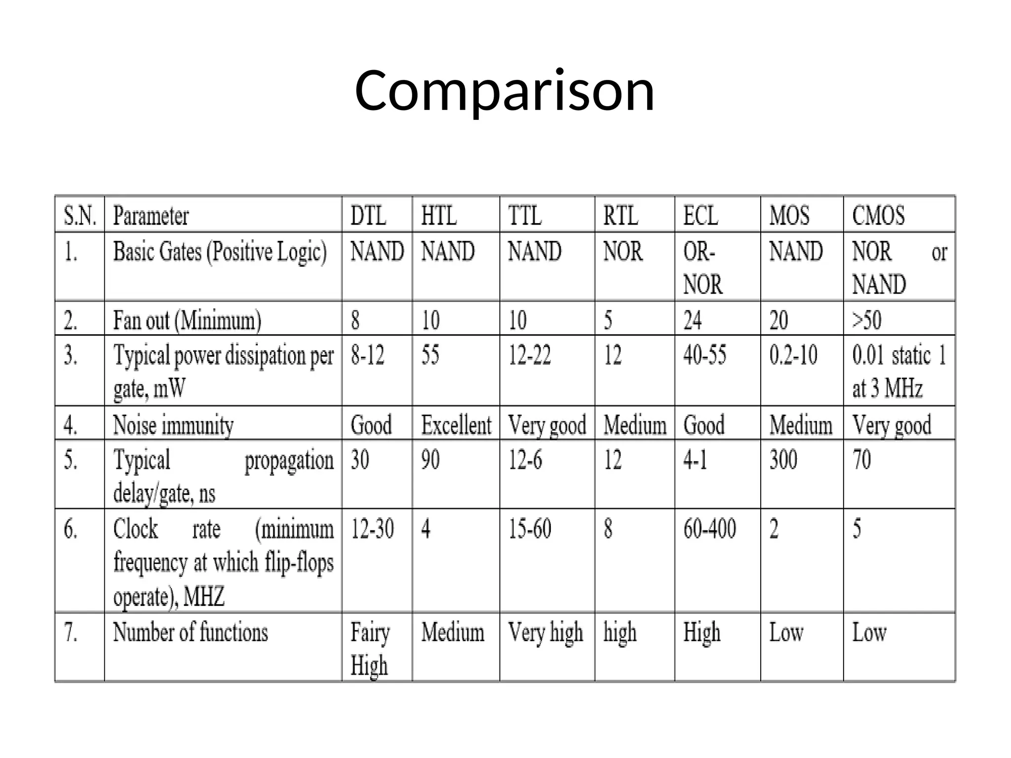
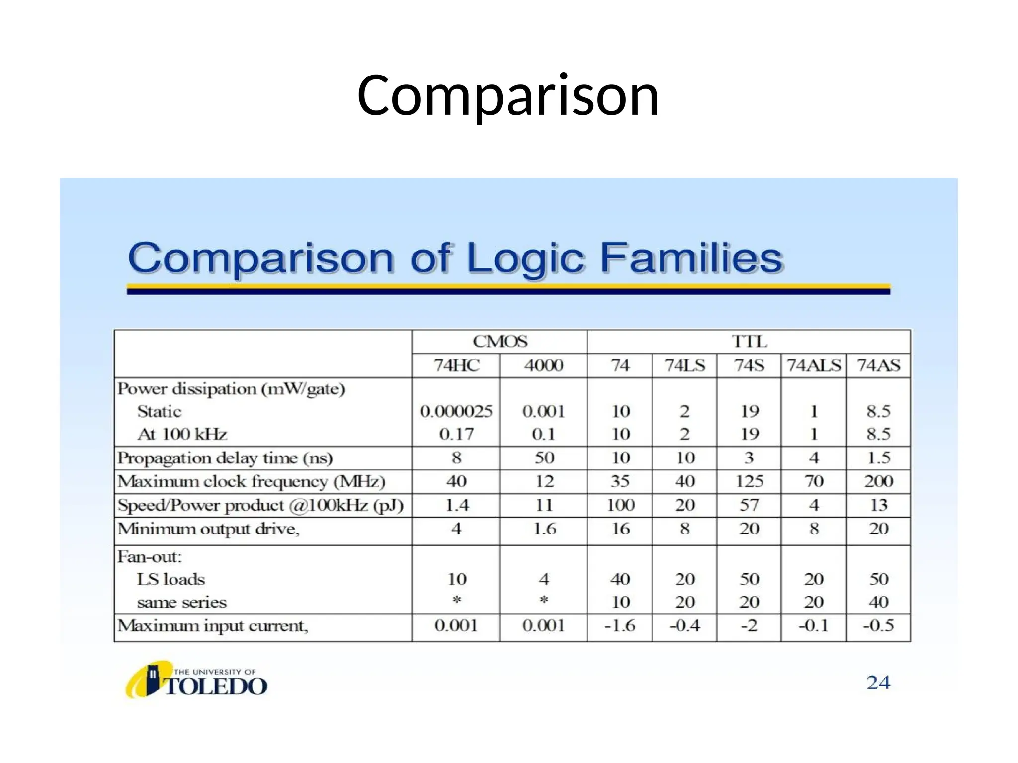
The characteristics whichare bound to be identical and used to compare performance are:
• Supply voltage range
• Speed of response
• Dissipation of power
• Input and output logic levels
• Current sinking capability
• Current sourcing capability
• Flexibility
• Noise immunity
• Fan-out
11.
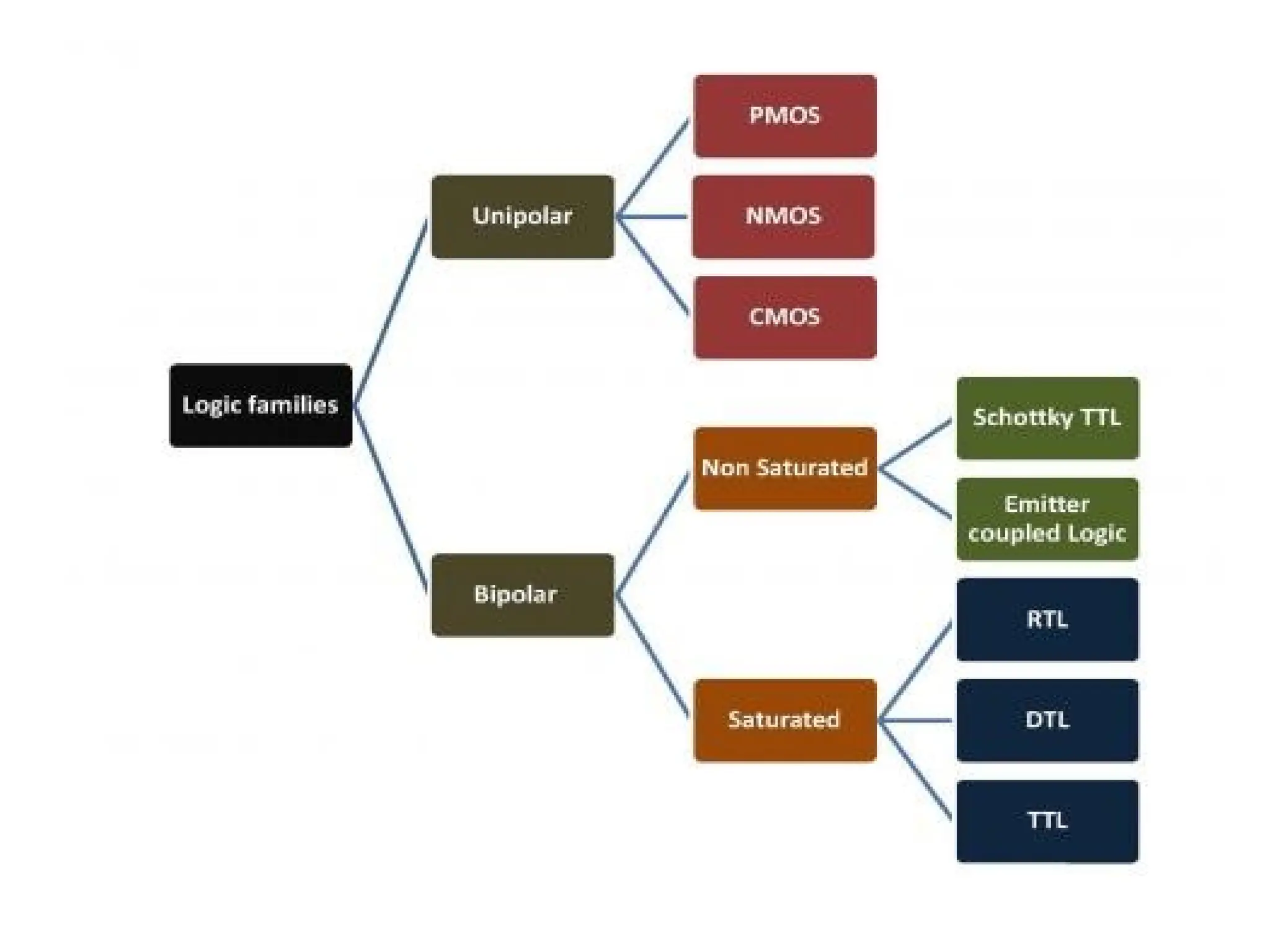
TYPES OF LOGICFAMILY
• The digital integrated circuits are designed
using bipolar devices or Metal Oxide
Semiconductor (MOS) or a combination of
both.
• There are two kinds of semiconductor devices.
The logic family which falls under the first
kind Bipolar logic family and the other
is Unipolar logic family.
12.
Classification Details
• Bipolarmeans two polarities. Bi- two, polar-polarities. Here, the
circuits have bipolar elements like diodes, transistors, etc.
• Other passive elements, like resistors and capacitors, also make
up the circuit.
• We can divide bipolar families further divided into saturated and
unsaturated logic families.
• Under the saturated logic families, the transistors used in ICs are
driven into saturation. And vice-versa for the unsaturated logic
systems.
• Unipolar families have components with only one polarity. The
circuits have unipolar components like MOSFETs and passive
elements.
13.
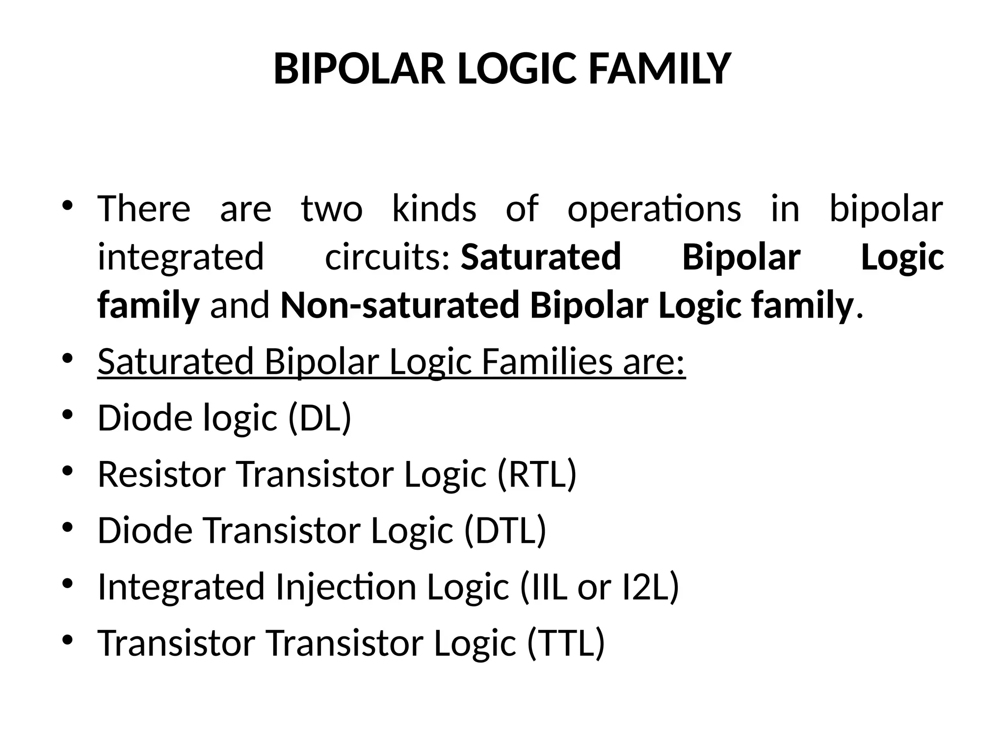
BIPOLAR LOGIC FAMILY
•There are two kinds of operations in bipolar
integrated circuits: Saturated Bipolar Logic
family and Non-saturated Bipolar Logic family.
• Saturated Bipolar Logic Families are:
• Diode logic (DL)
• Resistor Transistor Logic (RTL)
• Diode Transistor Logic (DTL)
• Integrated Injection Logic (IIL or I2L)
• Transistor Transistor Logic (TTL)
14.
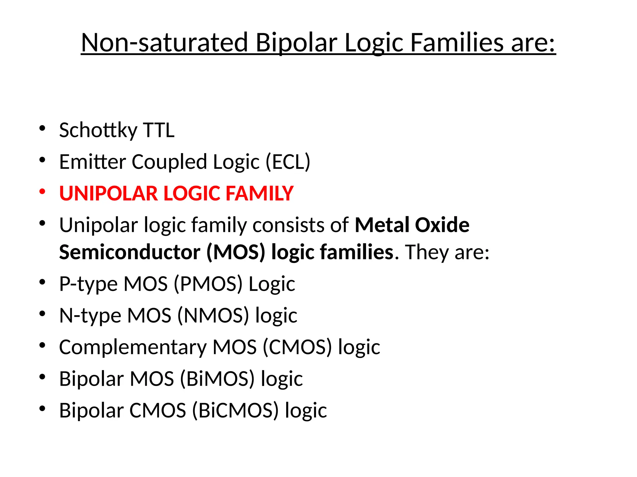
Non-saturated Bipolar LogicFamilies are:
• Schottky TTL
• Emitter Coupled Logic (ECL)
• UNIPOLAR LOGIC FAMILY
• Unipolar logic family consists of Metal Oxide
Semiconductor (MOS) logic families. They are:
• P-type MOS (PMOS) Logic
• N-type MOS (NMOS) logic
• Complementary MOS (CMOS) logic
• Bipolar MOS (BiMOS) logic
• Bipolar CMOS (BiCMOS) logic
15.
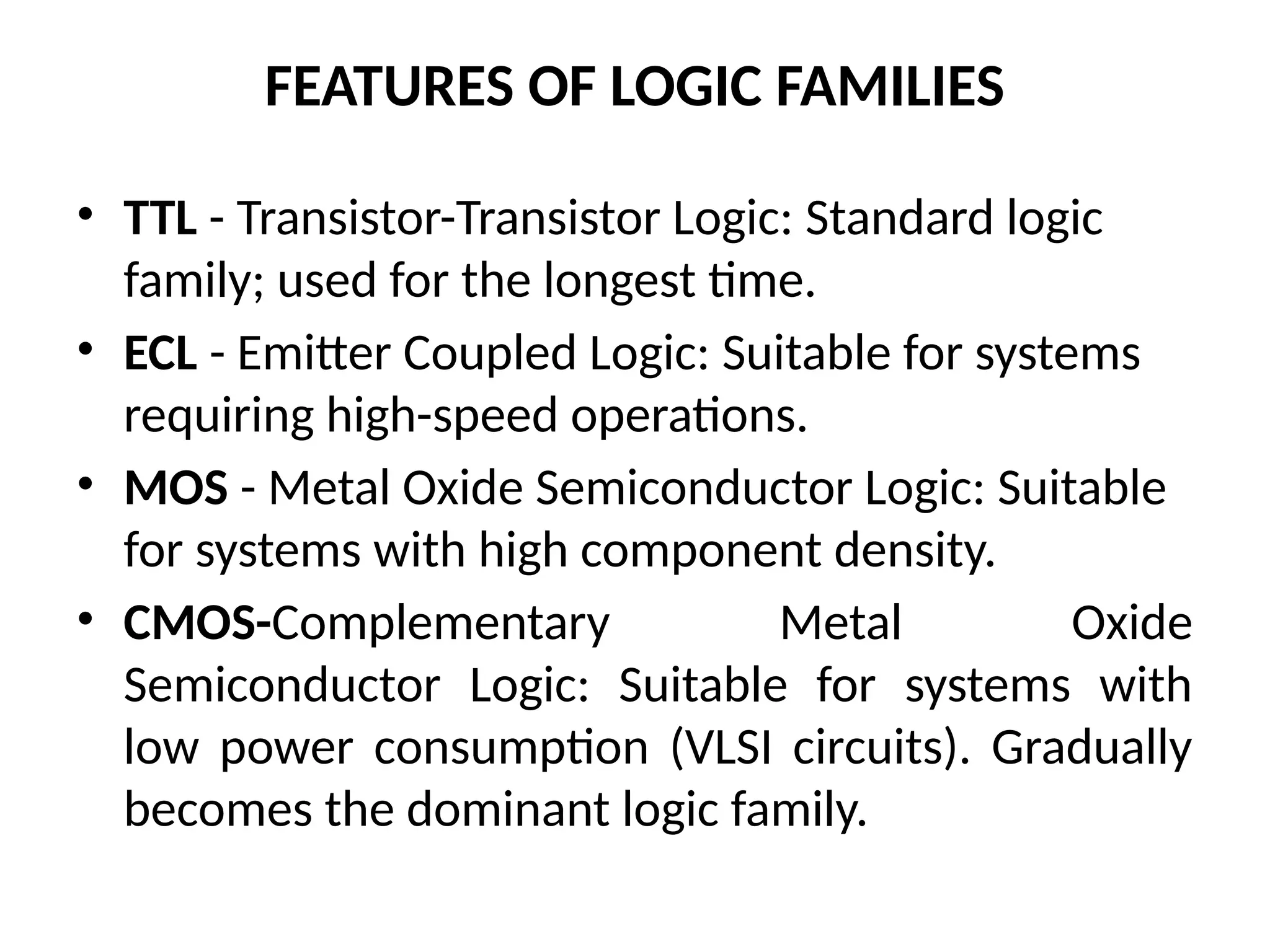
FEATURES OF LOGICFAMILIES
• TTL - Transistor-Transistor Logic: Standard logic
family; used for the longest time.
• ECL - Emitter Coupled Logic: Suitable for systems
requiring high-speed operations.
• MOS - Metal Oxide Semiconductor Logic: Suitable
for systems with high component density.
• CMOS-Complementary Metal Oxide
Semiconductor Logic: Suitable for systems with
low power consumption (VLSI circuits). Gradually
becomes the dominant logic family.
Definitions
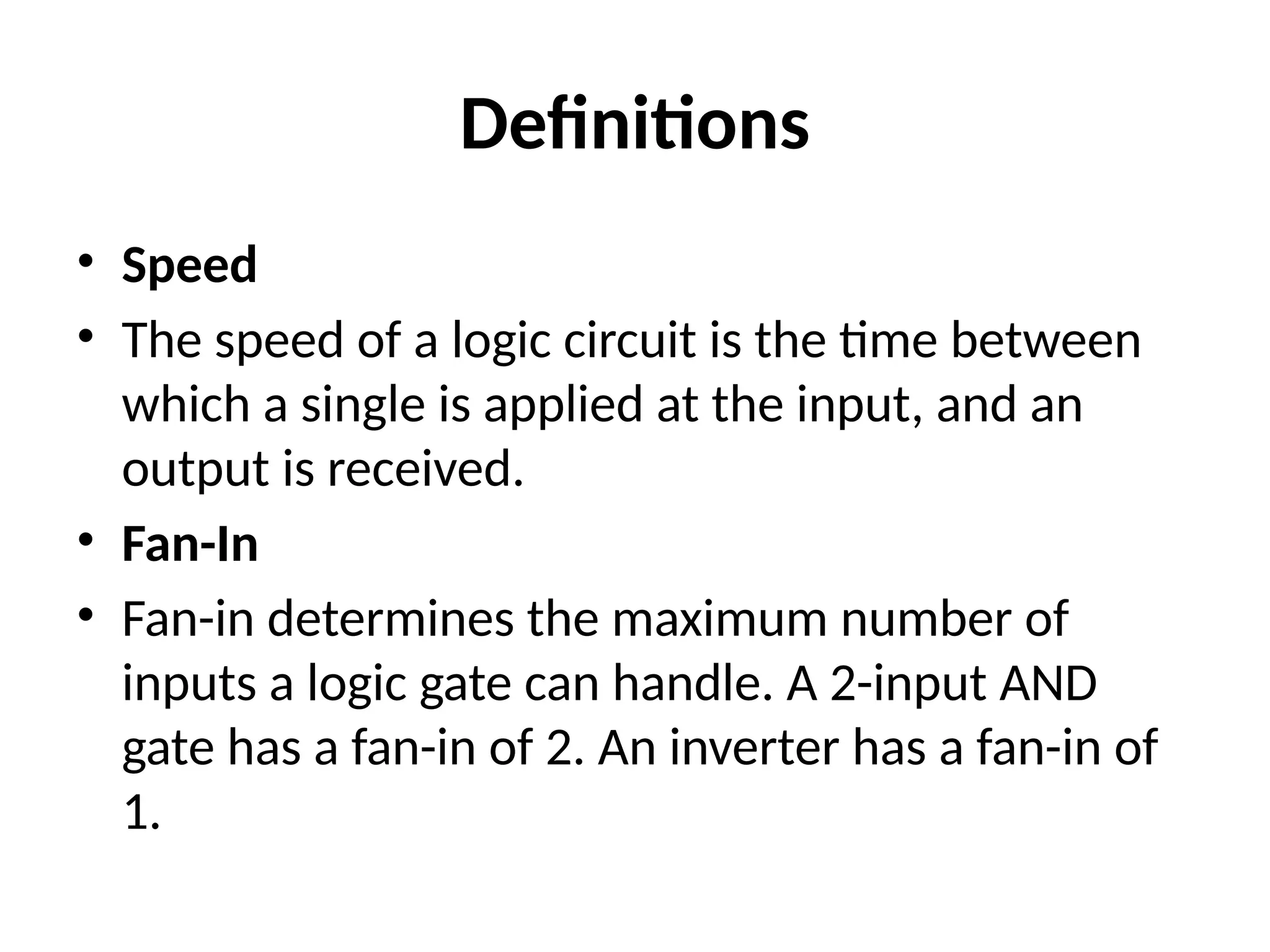
• Speed
• Thespeed of a logic circuit is the time between
which a single is applied at the input, and an
output is received.
• Fan-In
• Fan-in determines the maximum number of
inputs a logic gate can handle. A 2-input AND
gate has a fan-in of 2. An inverter has a fan-in of
1.
19.
Definitions
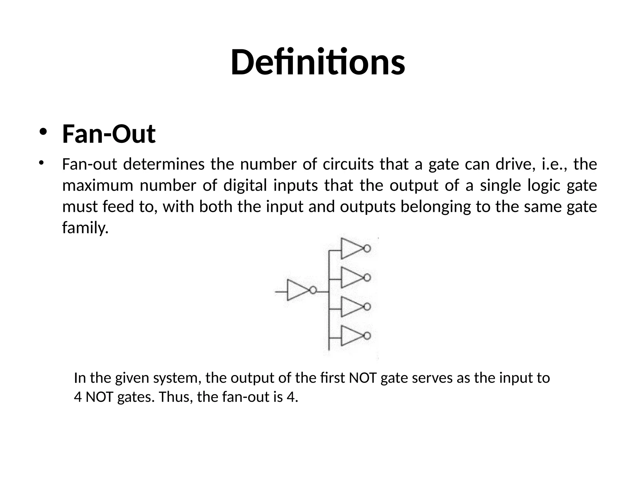
• Fan-Out
• Fan-outdetermines the number of circuits that a gate can drive, i.e., the
maximum number of digital inputs that the output of a single logic gate
must feed to, with both the input and outputs belonging to the same gate
family.
In the given system, the output of the first NOT gate serves as the input to
4 NOT gates. Thus, the fan-out is 4.
20.
Definitions
• Noise Immunity
•It is the maximum noise any circuit can handle without
affecting the output.
• Propagation Delay
• Propagation delay is measured as the time between
which input is applied to a system, and it affects the
output. It is measured at 50% marks.
• Power Dissipation
• It is the product of the current which enters the circuit
and the total voltage loss of the system
21.
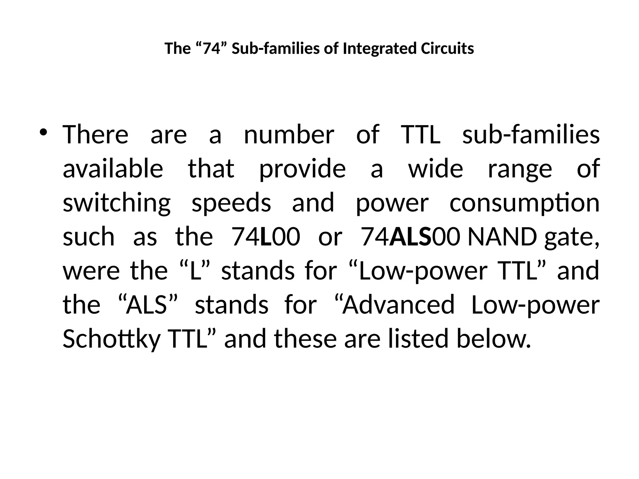
The “74” Sub-familiesof Integrated Circuits
• There are a number of TTL sub-families
available that provide a wide range of
switching speeds and power consumption
such as the 74L00 or 74ALS00 NAND gate,
were the “L” stands for “Low-power TTL” and
the “ALS” stands for “Advanced Low-power
Schottky TTL” and these are listed below.
22.
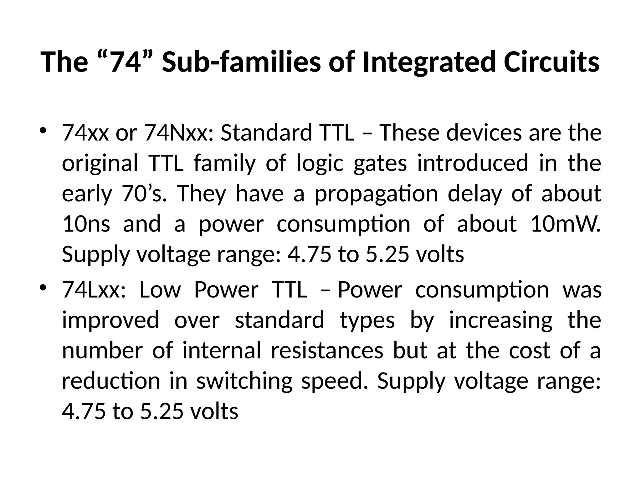
The “74” Sub-familiesof Integrated Circuits
• 74xx or 74Nxx: Standard TTL – These devices are the
original TTL family of logic gates introduced in the
early 70’s. They have a propagation delay of about
10ns and a power consumption of about 10mW.
Supply voltage range: 4.75 to 5.25 volts
• 74Lxx: Low Power TTL – Power consumption was
improved over standard types by increasing the
number of internal resistances but at the cost of a
reduction in switching speed. Supply voltage range:
4.75 to 5.25 volts
23.
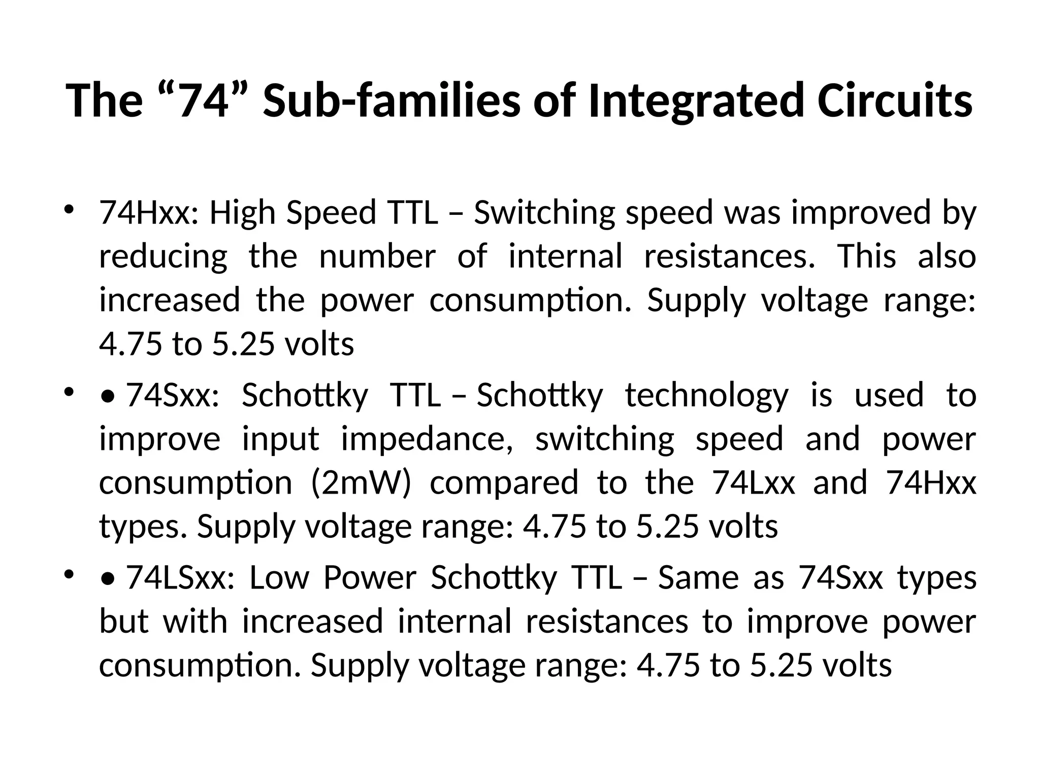
The “74” Sub-familiesof Integrated Circuits
• 74Hxx: High Speed TTL – Switching speed was improved by
reducing the number of internal resistances. This also
increased the power consumption. Supply voltage range:
4.75 to 5.25 volts
• • 74Sxx: Schottky TTL – Schottky technology is used to
improve input impedance, switching speed and power
consumption (2mW) compared to the 74Lxx and 74Hxx
types. Supply voltage range: 4.75 to 5.25 volts
• • 74LSxx: Low Power Schottky TTL – Same as 74Sxx types
but with increased internal resistances to improve power
consumption. Supply voltage range: 4.75 to 5.25 volts
24.
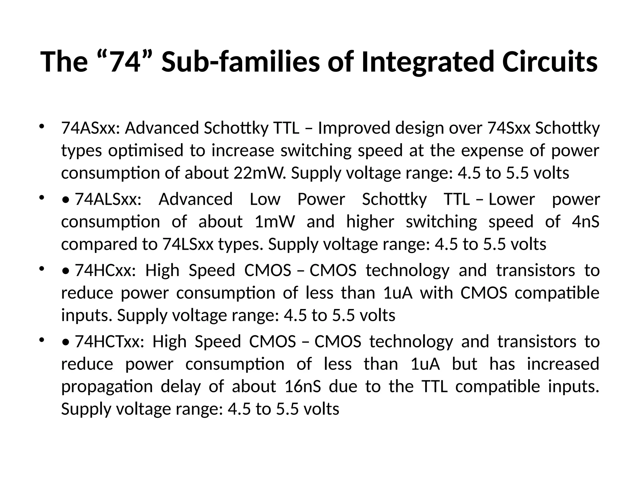
The “74” Sub-familiesof Integrated Circuits
• 74ASxx: Advanced Schottky TTL – Improved design over 74Sxx Schottky
types optimised to increase switching speed at the expense of power
consumption of about 22mW. Supply voltage range: 4.5 to 5.5 volts
• • 74ALSxx: Advanced Low Power Schottky TTL – Lower power
consumption of about 1mW and higher switching speed of 4nS
compared to 74LSxx types. Supply voltage range: 4.5 to 5.5 volts
• • 74HCxx: High Speed CMOS – CMOS technology and transistors to
reduce power consumption of less than 1uA with CMOS compatible
inputs. Supply voltage range: 4.5 to 5.5 volts
• • 74HCTxx: High Speed CMOS – CMOS technology and transistors to
reduce power consumption of less than 1uA but has increased
propagation delay of about 16nS due to the TTL compatible inputs.
Supply voltage range: 4.5 to 5.5 volts