Download as PDF, PPTX


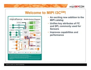
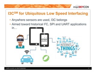
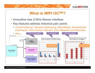

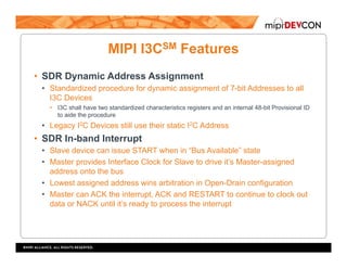
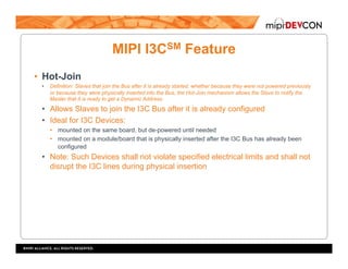
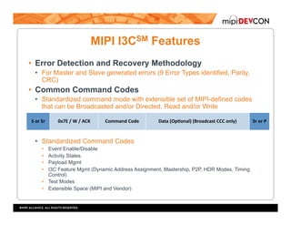
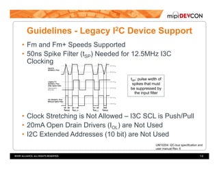
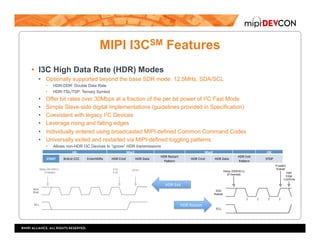
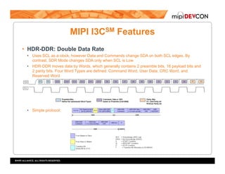

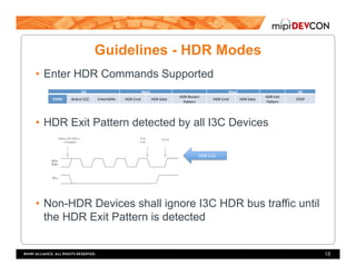
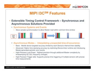


The document is a developer's guide to MIPI I3C implementation, outlining features, implementation guidelines, and design practices for this new 2-wire sensor interface. MIPI I3C improves upon legacy standards like I2C and SPI with enhanced performance characteristics, including dynamic addressing, error detection, and high data rates. It emphasizes the roles of timing control and varied topologies, ensuring compatibility with existing devices while offering innovative approaches for low-power interfacing and sensor integration.


