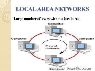
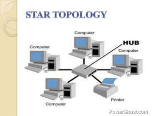
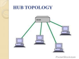
This document discusses several topics related to optical fiber communication systems including:
1. Factors that limit the performance of amplified fiber links such as transmission distance, data rate, and component costs.
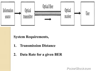
2. System requirements including transmission distance, data rate, fiber type, and receiver sensitivities.
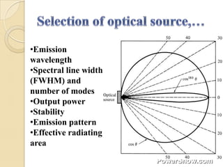
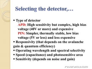
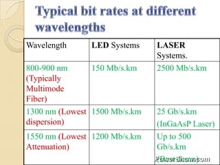
3. Key components of fiber optic systems and their specifications including lasers, detectors, and other elements.
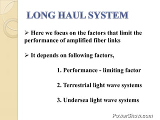
4. Performance limiting factors for terrestrial and undersea lightwave systems.
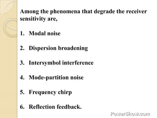
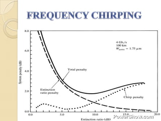
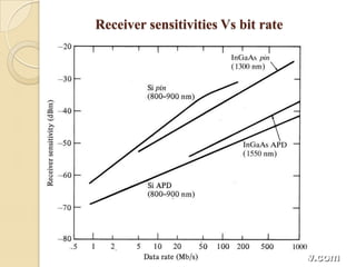
5. Physical phenomena that degrade receiver sensitivity in realistic lightwave systems including modal noise and dispersion broadening.


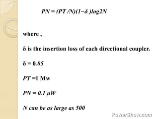
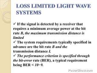
![PN = PTC[(1−δ )(1−C)]N−1
where ,
PT is the transmitted power
C is the fraction of power coupled out at each tap
δ accounts for insertion losses, assumed to be the
same at each tap
N should not exceed 60.](https://image.slidesharecdn.com/light-wave-system-3855513-130118082800-phpapp01/85/Light-wave-system-3855513-11-320.jpg)


![• The rise time Tr of a linear system is defined as the
time during which the response increases from 10 to
90% of its final output value when the input is
changed abruptly.
• When the input voltage across an RC circuit
changes instantaneously from 0 to V0, the output
voltage changes as,
Vout(t) =V0[1−exp(−t/RC)]](https://image.slidesharecdn.com/light-wave-system-3855513-130118082800-phpapp01/85/Light-wave-system-3855513-25-320.jpg)