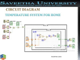
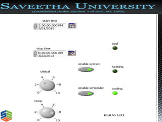
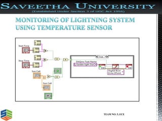
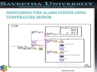
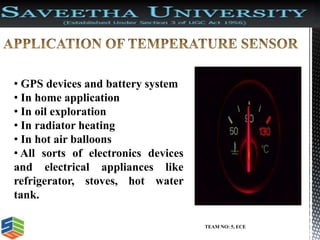
This document discusses the design of a temperature sensor circuit using LabVIEW. It contains information about thermistors and how their resistance varies with temperature. The document outlines that the goal is to design the temperature sensor circuit in LabVIEW and analyze temperature variation over time for different applications. It provides details about the front panel and block diagram of LabVIEW programs. Common temperature sensors like thermocouples, thermistors, and silicon sensors are described. Applications of temperature sensors in systems like GPS devices, homes, oil exploration, and electronics are listed.
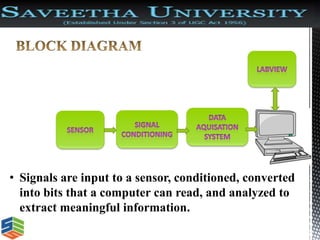


![Tamperature controlled fan_project_report[1]](https://cdn.slidesharecdn.com/ss_thumbnails/tamperaturecontrolledfanprojectreport1-170912121052-thumbnail.jpg?width=640&height=640&fit=bounds)


