Downloaded 306 times

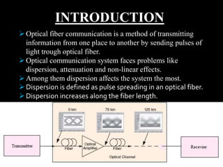
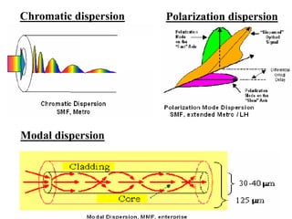
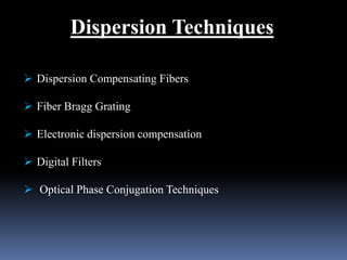
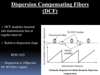
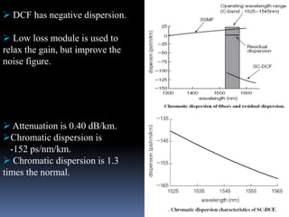
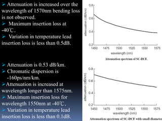
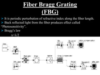
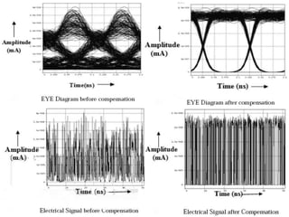

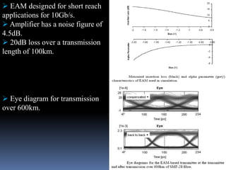
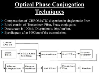
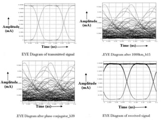
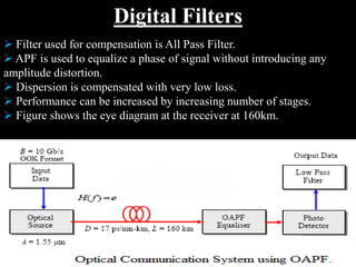
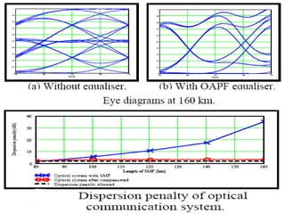

This document discusses dispersion in optical fiber communication systems and various techniques to compensate for it, including dispersion compensating fibers, fiber Bragg gratings, electronic dispersion compensation, digital filters, and optical phase conjugation. Dispersion increases pulse spreading and affects signal quality. These techniques help reduce dispersion to improve transmission over long distances. The document compares the advantages and disadvantages of each technique.


![Available online at [www.ijeete.com]EFFECT OF DISPERSION AND FIBER LENGTH ON ...](https://cdn.slidesharecdn.com/ss_thumbnails/ij-v02-1516-e171-160112094437-thumbnail.jpg?width=640&height=640&fit=bounds)


