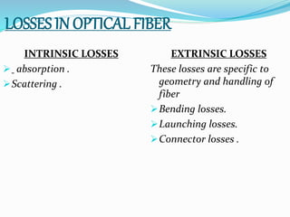
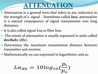
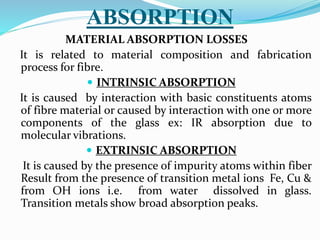
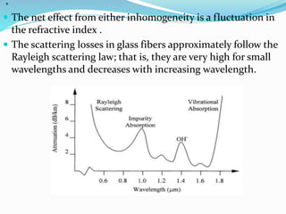
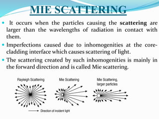
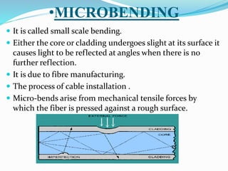
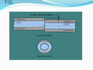
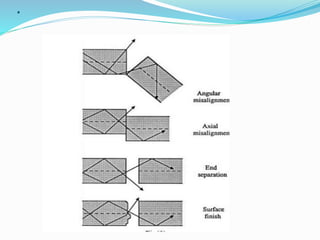
.
.
DEPARTMENT OF PHYSICS
SUBMITTED BY
SANDHYA SINGH
SUBMITTED TO
DR. RAJNEESH KUMAR VERM
LOSSES IN OPTICAL FIBER
INTRINSIC LOSSES
 absorption .
Scattering .
EXTRINSIC LOSSES
These losses are specific to
geometry and handling of
fiber
Bending losses.
Launching losses.
Connector losses .
ATTENUATION
 Attenuation is a general term that refers to any reduction in
the strength of a signal. . Sometimes called loss, attenuation
is a natural consequence of signal transmission over long
distances.
 It is also called signal loss or fiber loss.
 The extent of attenuation is usually expressed in units called
decibels (dBs).
 Determines the maximum transmission distance between
transmitter and receiver.
 Mathematically we can expressed in logarithmic unit as-
ABSORPTION
MATERIAL ABSORPTION LOSSES
It is related to material composition and fabrication
process for fibre.
 INTRINSIC ABSORPTION
It is caused by interaction with basic constituents atoms
of fibre material or caused by interaction with one or more
components of the glass ex: IR absorption due to
molecular vibrations.
 EXTRINSIC ABSORPTION
It is caused by the presence of impurity atoms within fiber
Result from the presence of transition metal ions Fe, Cu &
from OH ions i.e. from water dissolved in glass.
Transition metals show broad absorption peaks.
MATERIAL SCATTERING LOSSES
 Despite the careful manufacturing techniques, most fibers
are inhomogeneous that have disordered, amorphous
structures. Power losses due to scattering are caused by such
imperfections in the core material and irregularities between
the junction and cladding .
 Inhomogeneities can be either structural or compositional in
nature.
.
 The net effect from either inhomogeneity is a fluctuation in
the refractive index .
 The scattering losses in glass fibers approximately follow the
Rayleigh scattering law; that is, they are very high for small
wavelengths and decreases with increasing wavelength.
LINEAR SCATTERING LOSSES
 In it there is transfer of some or all the optical power
contained within one propogation mode into different
mode.
 Now when the transfer takes place to leaky or radiation
mode then the result is attenuated .
 It is caused by inhomogeneties in the fibre core materials
and any cracks or imperfections in the coating and
interface.
 It can be divided into 2 major categories
Mie scattering.
Rayleigh scattering.
RAYLEIGH SCATTERING
 For glass fibers the foremost type of scattering is Rayleigh
scattering. With this process, atoms or other particles
within the fiber absorb the light signal and instantly re-
emits the light in another direction.
 In this way Rayleigh scattering appears very much like
absorption but it absorbs and redirects the light so quickly
that is considered scattering.
 It occurs when the dimensions of the scatter is much
smaller than the wavelength of incident radiation.
 It is strong wavelength dependent.
 The dominant reason behind Rayleigh scattering is
refractive index
MIE SCATTERING
 It occurs when the particles causing the scattering are
larger than the wavelengths of radiation in contact with
them.
 Imperfections caused due to inhomogenities at the core-
cladding interface which causes scattering of light.
 The scattering created by such inhomogenities is mainly in
the forward direction and is called Mie scattering.
NON-LINEAR SCATTERING
 This scattering cause disproportionate attenuation,
usually at high optical power levels due to nonlinear
behaviour.
 This non linear scattering causes the optical power from
one mode to be transferred in either the forward or
backward direction to the same, or other modes, at a
different frequency.
 Non Linear scattering may be categorized as:
Stimulated Brillouin scattering (SBS)
Stimulated Raman scattering (SRS)
RADIATIVE LOSSES
 Also called bending losses occur when fibre is curved .
Bending losses are the result of distortion of fiber from
ideal straight line configuration
 Attenuation occurring as a result of either a bend in an
optical fiber that exceeds the minimum bend radius or an
abrupt discontinuity in the core/cladding interface.The
incident light rays strike the boundary between the core and
the cladding at an angle less than the critical angle and
enter the cladding, where they are lost.
bending losses are of 2 types:
 Macrobending losses.
 Microbending losses.
•MICROBENDING
 It is called small scale bending.
 Either the core or cladding undergoes slight at its surface it
causes light to be reflected at angles when there is no
further reflection.
 It is due to fibre manufacturing.
 The process of cable installation .
 Micro-bends arise from mechanical tensile forces by
which the fiber is pressed against a rough surface.
• MACROBENDING
 A relatively large bend in an fiber optic cable.
 Macro bending losses occur when the fiber cable is
subjected to a significant amount of bending above a
critical value of curvature. Such losses are also called as
large radius losses.
 Bending in which complete fibre undergoes bends which
cause certain modes not to reflected & therefore causes loss
to the cladding
 Hence the energy associated mode in cladding is lost
through radiation .
. To minimize the losses following precautions are taken
 While manufacturing the cable; a precise control of core
diameter is maintained.
 A compressible jacket is fitted over the fiber, so that when
the external pressure is applied then the deformation of
jacket takes place and there will not be creation of micro
bends in the core layer of fiber.
 Furthermore, the fiber cabling must be capable of
maintaining this situation under all the strain and
environmental conditions envisaged in its lifetime.
LAUNCHING LOSSES
 The end at which the light enters the fibre is called launching
end.
 The term launching loss refers to an optical fibre not being
able to propogate all incoming light rays from an optical
source
 These occur during the process of coupling light with the
fiber (ex. Losses at the interface stages).
 Techniques have been developed to realize efficient coupling
between light source & fiber, mainly achieved by means of
condenses & focusing lens.
•CONNECTOR LOSSES
 Connector losses are associated with coupling of output of
one fiber with the input of another fiber.
 The significant losses may arise in fiber connectors & splices
of cores of joined fibers having unequal diameter or
misaligned centres.
 The simplest way to avoid connector loss is by splicing the
two ends of fiber permanentaly either by gluing or by fusing
at high temperature.
 Losses due to some imperfection in splicing caused by
misalignment like longitudinal, lateral, end separation etc.
FIG.
.

Optical fiber

  • 1.
    . . DEPARTMENT OF PHYSICS SUBMITTEDBY SANDHYA SINGH SUBMITTED TO DR. RAJNEESH KUMAR VERM LOSSES IN OPTICAL FIBER
  • 2.
    LOSSES IN OPTICALFIBER INTRINSIC LOSSES  absorption . Scattering . EXTRINSIC LOSSES These losses are specific to geometry and handling of fiber Bending losses. Launching losses. Connector losses .
  • 3.
    ATTENUATION  Attenuation isa general term that refers to any reduction in the strength of a signal. . Sometimes called loss, attenuation is a natural consequence of signal transmission over long distances.  It is also called signal loss or fiber loss.  The extent of attenuation is usually expressed in units called decibels (dBs).  Determines the maximum transmission distance between transmitter and receiver.  Mathematically we can expressed in logarithmic unit as-
  • 4.
    ABSORPTION MATERIAL ABSORPTION LOSSES Itis related to material composition and fabrication process for fibre.  INTRINSIC ABSORPTION It is caused by interaction with basic constituents atoms of fibre material or caused by interaction with one or more components of the glass ex: IR absorption due to molecular vibrations.  EXTRINSIC ABSORPTION It is caused by the presence of impurity atoms within fiber Result from the presence of transition metal ions Fe, Cu & from OH ions i.e. from water dissolved in glass. Transition metals show broad absorption peaks.
  • 5.
    MATERIAL SCATTERING LOSSES Despite the careful manufacturing techniques, most fibers are inhomogeneous that have disordered, amorphous structures. Power losses due to scattering are caused by such imperfections in the core material and irregularities between the junction and cladding .  Inhomogeneities can be either structural or compositional in nature.
  • 6.
    .  The neteffect from either inhomogeneity is a fluctuation in the refractive index .  The scattering losses in glass fibers approximately follow the Rayleigh scattering law; that is, they are very high for small wavelengths and decreases with increasing wavelength.
  • 7.
    LINEAR SCATTERING LOSSES In it there is transfer of some or all the optical power contained within one propogation mode into different mode.  Now when the transfer takes place to leaky or radiation mode then the result is attenuated .  It is caused by inhomogeneties in the fibre core materials and any cracks or imperfections in the coating and interface.  It can be divided into 2 major categories Mie scattering. Rayleigh scattering.
  • 8.
    RAYLEIGH SCATTERING  Forglass fibers the foremost type of scattering is Rayleigh scattering. With this process, atoms or other particles within the fiber absorb the light signal and instantly re- emits the light in another direction.  In this way Rayleigh scattering appears very much like absorption but it absorbs and redirects the light so quickly that is considered scattering.  It occurs when the dimensions of the scatter is much smaller than the wavelength of incident radiation.  It is strong wavelength dependent.  The dominant reason behind Rayleigh scattering is refractive index
  • 9.
    MIE SCATTERING  Itoccurs when the particles causing the scattering are larger than the wavelengths of radiation in contact with them.  Imperfections caused due to inhomogenities at the core- cladding interface which causes scattering of light.  The scattering created by such inhomogenities is mainly in the forward direction and is called Mie scattering.
  • 10.
    NON-LINEAR SCATTERING  Thisscattering cause disproportionate attenuation, usually at high optical power levels due to nonlinear behaviour.  This non linear scattering causes the optical power from one mode to be transferred in either the forward or backward direction to the same, or other modes, at a different frequency.  Non Linear scattering may be categorized as: Stimulated Brillouin scattering (SBS) Stimulated Raman scattering (SRS)
  • 11.
    RADIATIVE LOSSES  Alsocalled bending losses occur when fibre is curved . Bending losses are the result of distortion of fiber from ideal straight line configuration  Attenuation occurring as a result of either a bend in an optical fiber that exceeds the minimum bend radius or an abrupt discontinuity in the core/cladding interface.The incident light rays strike the boundary between the core and the cladding at an angle less than the critical angle and enter the cladding, where they are lost. bending losses are of 2 types:  Macrobending losses.  Microbending losses.
  • 12.
    •MICROBENDING  It iscalled small scale bending.  Either the core or cladding undergoes slight at its surface it causes light to be reflected at angles when there is no further reflection.  It is due to fibre manufacturing.  The process of cable installation .  Micro-bends arise from mechanical tensile forces by which the fiber is pressed against a rough surface.
  • 13.
    • MACROBENDING  Arelatively large bend in an fiber optic cable.  Macro bending losses occur when the fiber cable is subjected to a significant amount of bending above a critical value of curvature. Such losses are also called as large radius losses.  Bending in which complete fibre undergoes bends which cause certain modes not to reflected & therefore causes loss to the cladding  Hence the energy associated mode in cladding is lost through radiation .
  • 14.
    . To minimizethe losses following precautions are taken  While manufacturing the cable; a precise control of core diameter is maintained.  A compressible jacket is fitted over the fiber, so that when the external pressure is applied then the deformation of jacket takes place and there will not be creation of micro bends in the core layer of fiber.  Furthermore, the fiber cabling must be capable of maintaining this situation under all the strain and environmental conditions envisaged in its lifetime.
  • 15.
    LAUNCHING LOSSES  Theend at which the light enters the fibre is called launching end.  The term launching loss refers to an optical fibre not being able to propogate all incoming light rays from an optical source  These occur during the process of coupling light with the fiber (ex. Losses at the interface stages).  Techniques have been developed to realize efficient coupling between light source & fiber, mainly achieved by means of condenses & focusing lens.
  • 16.
    •CONNECTOR LOSSES  Connectorlosses are associated with coupling of output of one fiber with the input of another fiber.  The significant losses may arise in fiber connectors & splices of cores of joined fibers having unequal diameter or misaligned centres.  The simplest way to avoid connector loss is by splicing the two ends of fiber permanentaly either by gluing or by fusing at high temperature.  Losses due to some imperfection in splicing caused by misalignment like longitudinal, lateral, end separation etc.
  • 17.
  • 18.