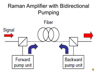
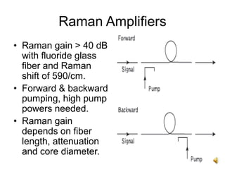
1
Raman Fiber Amplifiers
MEC
2
Contents
• Introduction.
• Stimulated Raman Scattering.
• Raman Amplifiers and Classifications.
• Raman Gain.
• Noise and Interference.
- ASE Noise
- Double Rayleigh Scattering Reflections.
- Relative Intensity Noise.
• Deployment Issues and Applications.
3
Introduction
• Ability of light to scatter inelastically on a
molecular structure (gas, liquid or solid)
and exchange energy with material
discovered by Sir. C. V. Raman in 1928.
• Effect known as ‘Raman scattering’.
• Incoming photon either red-shifted (Stokes
shift) or blue-shifted (anti-Stokes shift) by
interaction with the medium.
4
Introduction
• Fraction of photon energy absorbed or
emitted by the material as molecular
vibrations (heat) - phonons.
• Raman scattering occur in all materials,
dominant in silica glass.
• Raman transitions due to bending motion of
Si-O-Si bond.
• Raman scattering is inelastic, molecule will
decay to a vibrational level different from
initial state.
5
Introduction
• Stokes Raman scattering - final energy level
of the molecule higher than the initial level.
• Anti-Stokes Raman scattering - final energy
level lower than the starting level.
• Stokes scattering is more common.
• For Stokes shift,
νp,νs - frequency of pump and Stokes photon,
Ephonon – phonon energy.
6
Introduction
7
Raman Amplifiers
• Nonlinear effects within optical fiber used
to provide optical amplification.
• Amplification achieved using Stimulated
Raman Scattering (SRS).
• Self-phase matching between the pump
and the signal.
• Broad gain–bandwidth and fast response,
attractive for WDM systems.
8
Raman Amplifiers
• Provide gain over the entire fiber band (i.e.
0.8 to 1.6 μm).
• Pump signal optical wavelengths typically
500/cm higher in frequency than signal to
be amplified.
• Multiple pump wavelengths for flat gain,
reduce polarisation dependent gain.
• Broad spectral bandwidth of up to 100 nm
with suitable fiber doping.
• Continuous-wave Raman gains exceed 20
dB.
9
Raman Amplifier with Bidirectional
Pumping
10
Stimulated Raman Scattering
• Nonlinear scattering observed at high optical
power densities in long single-mode fibers.
• Provide optical gain with frequency shift.
• Useful for optical amplification.
• Modulates light through thermal molecular
vibrations within the fiber.
• Scattered light appears as upper and lower
sidebands separated from incident light by
the modulation frequency.
11
Stimulated Raman Scattering
• High-frequency optical phonon generated
in the scattering process.
• Bidirectional - forward and backward
directions.
• Threshold optical power for SRS:
d - fiber core diameter, λ - operating
wavelength, αdB - fiber attenuation, dB/km.
12
Raman Amplifiers
• Raman gain > 40 dB
with fluoride glass
fiber and Raman
shift of 590/cm.
• Forward & backward
pumping, high pump
powers needed.
• Raman gain
depends on fiber
length, attenuation
and core diameter.
13
Raman Gain
• Raman Gain
gR - Power Raman gain coefficient, Aeff and
Leff - effective core cross-sectional area and
length, k - numerical factor that accounts for
polarization scrambling between optical pump
and signal, reff - effective core radius, αp -fiber
transmission loss at pump wavelength, L -
actual fiber length, Pp – pump power.
14
Raman Gain
• k = 2 for complete polarization scrambling,
as in conventional single-mode fiber.
• Raman gain efficiency (gR/Aeffk) measured
in W−1 km−1.
• Raman gain becomes larger as fiber
lengths increase up to around 50 km,
asymptotically it reaches a constant value.
• Higher Raman gains obtained with lower
loss fibers and lower core diameters.
15
Raman Gain
10 μm core single-mode fibers.
Pump input power = 1.6 W
16
On-Off Gain
• On-off gain of Raman amplifier - increase in
signal output power when pumps are turned
on.
• Distributed Amplification - gain in the
transmission fiber itself, reduces system
signal-to-noise ratio (SNR) degradation,
compared with discrete amplifier (only)
systems.
17
Raman Amplifier Classifications
• Main categories – discrete, distributed and
hybrid.
• Discrete Raman amplifiers/Lump Raman
amplifiers used as lumped elements
inserted into transmission line for gain.
• Discrete - pump power is confined to the
lumped element (~20 km long fiber).
• Distributed Raman amplifier extends pump
power into transmission line fiber.
18
Raman Amplifier Classifications
• Discrete amplifiers - amplification takes
place at a single point at the end of the
link.
• Distributed amplifiers - amplification takes
place along the fiber, avoids low power at
the end of the link, allows lower power to
be launched at the starting of the link.
• DRA prevents signal attenuation to very
low powers, improves SNR.
19
Raman Amplifier Classifications
• Distributed - amplification takes place
along several kilometers of fiber(~100 km).
• Hybrid Raman Amplifiers - Lumped and
distributed Raman fiber amplifiers
combined for wideband applications.
• Combined amplification increases overall
amplified spectral bandwidth.
• Amplified Spectral Emission (ASE) noise &
Double Rayleigh scattering reflections.
20
Raman Amplifier vs EDFA
21
Noise and Interference
• Selection & number of pump signals
influence amplifier noise.
• ASE contributes most of the noise.
• Common sources of noise include:
- Beating of the signal with ASE due to
double Rayleigh scattering reflections or
multipath interference.
- Non Linear Effects - four-wave mixing,
self-phase modulation, cross-phase
modulation.
• Relative Intensity Noise.
22
Double Rayleigh Scattering
Reflections
• Fiber length influences noise within
Raman amplifiers.
• Magnitude proportional to fiber length.
• ASE noise reflected together with signal,
cause it to increase several times.
• Effect of double Rayleigh scattering
reflections reduced if multiple stages of
amplification over full fiber length.
23
Relative Intensity Noise
• Pump signal and input signal interact for a
longer time over several fiber kilometers.
• Fluctuations in pump power (pump noise)
transferred to transmitted signal.
• Pump noise also called Relative Intensity
Noise (RIN).
• Severe if multiple pump signals used to
achieve wideband amplification.
24
Minimising RIN
• Reduce interaction time between pump
and input signal.
• Achieved by backward pumping – counter-
propagation of signals where interaction
time for pump and signal is very short.
25
Other Limitations
• Low power efficiency.
• Safety issues due to high optical powers in
the fiber.
• Enhanced problems with nonlinearities,
due to high path-average power in fibers.
• Gain limited by available pump powers
and wavelengths.
26
Laser Safety
• Output power of Raman pump modules
higher than typical power levels in EDFA
systems.
• DRA generate ASE along transmission line.
• Even in case of fiber break, ASE power within
C - band can propagate along the system.
• Reducing power to a safe level in case of
accidental connection opening/fiber break.
• Detection of fiber break/open connector,
allow automatic shut down of Raman pump
module.
27
Gain Measurement
• Achievable Raman gain and shape of gain
spectrum depends on fiber type and
quality of fiber line.
• Achievable gain vary from spool to spool
due to manufacturing variations.
• Ability for accurate real time Raman gain
measurement.
• Adjust pump powers to achieve desired
average gain and gain shape.
28
System Integration
• Integrating DRA modules into existing
system architecture time consuming and
costly.
• Tight integration of Raman and EDFA
modules allow module parameter
optimization, enhanced gain flatness.
• Stand alone Raman amplifiers to extend
existing capabilities.
29
Applications
• Long distance single span links
- undersea links between islands, remote
coastal locations, oil rigs etc.
- locations separated by mountain ranges
or desert.
- where commercial, legal or security
constraints render amplification sites
impractical.
30
Applications
• Long spans within multispan links.
- one or more spans longer than others.
- hut skipping : spans made intentionally
longer, skip repeaters to reduce capital
and operating expenditure.
• High capacity long distance systems.
• Optical amplifiers and waveguides in
general.
31
Thank You

Raman amplifiers

  • 1.
  • 2.
    2 Contents • Introduction. • StimulatedRaman Scattering. • Raman Amplifiers and Classifications. • Raman Gain. • Noise and Interference. - ASE Noise - Double Rayleigh Scattering Reflections. - Relative Intensity Noise. • Deployment Issues and Applications.
  • 3.
    3 Introduction • Ability oflight to scatter inelastically on a molecular structure (gas, liquid or solid) and exchange energy with material discovered by Sir. C. V. Raman in 1928. • Effect known as ‘Raman scattering’. • Incoming photon either red-shifted (Stokes shift) or blue-shifted (anti-Stokes shift) by interaction with the medium.
  • 4.
    4 Introduction • Fraction ofphoton energy absorbed or emitted by the material as molecular vibrations (heat) - phonons. • Raman scattering occur in all materials, dominant in silica glass. • Raman transitions due to bending motion of Si-O-Si bond. • Raman scattering is inelastic, molecule will decay to a vibrational level different from initial state.
  • 5.
    5 Introduction • Stokes Ramanscattering - final energy level of the molecule higher than the initial level. • Anti-Stokes Raman scattering - final energy level lower than the starting level. • Stokes scattering is more common. • For Stokes shift, νp,νs - frequency of pump and Stokes photon, Ephonon – phonon energy.
  • 6.
  • 7.
    7 Raman Amplifiers • Nonlineareffects within optical fiber used to provide optical amplification. • Amplification achieved using Stimulated Raman Scattering (SRS). • Self-phase matching between the pump and the signal. • Broad gain–bandwidth and fast response, attractive for WDM systems.
  • 8.
    8 Raman Amplifiers • Providegain over the entire fiber band (i.e. 0.8 to 1.6 μm). • Pump signal optical wavelengths typically 500/cm higher in frequency than signal to be amplified. • Multiple pump wavelengths for flat gain, reduce polarisation dependent gain. • Broad spectral bandwidth of up to 100 nm with suitable fiber doping. • Continuous-wave Raman gains exceed 20 dB.
  • 9.
    9 Raman Amplifier withBidirectional Pumping
  • 10.
    10 Stimulated Raman Scattering •Nonlinear scattering observed at high optical power densities in long single-mode fibers. • Provide optical gain with frequency shift. • Useful for optical amplification. • Modulates light through thermal molecular vibrations within the fiber. • Scattered light appears as upper and lower sidebands separated from incident light by the modulation frequency.
  • 11.
    11 Stimulated Raman Scattering •High-frequency optical phonon generated in the scattering process. • Bidirectional - forward and backward directions. • Threshold optical power for SRS: d - fiber core diameter, λ - operating wavelength, αdB - fiber attenuation, dB/km.
  • 12.
    12 Raman Amplifiers • Ramangain > 40 dB with fluoride glass fiber and Raman shift of 590/cm. • Forward & backward pumping, high pump powers needed. • Raman gain depends on fiber length, attenuation and core diameter.
  • 13.
    13 Raman Gain • RamanGain gR - Power Raman gain coefficient, Aeff and Leff - effective core cross-sectional area and length, k - numerical factor that accounts for polarization scrambling between optical pump and signal, reff - effective core radius, αp -fiber transmission loss at pump wavelength, L - actual fiber length, Pp – pump power.
  • 14.
    14 Raman Gain • k= 2 for complete polarization scrambling, as in conventional single-mode fiber. • Raman gain efficiency (gR/Aeffk) measured in W−1 km−1. • Raman gain becomes larger as fiber lengths increase up to around 50 km, asymptotically it reaches a constant value. • Higher Raman gains obtained with lower loss fibers and lower core diameters.
  • 15.
    15 Raman Gain 10 μmcore single-mode fibers. Pump input power = 1.6 W
  • 16.
    16 On-Off Gain • On-offgain of Raman amplifier - increase in signal output power when pumps are turned on. • Distributed Amplification - gain in the transmission fiber itself, reduces system signal-to-noise ratio (SNR) degradation, compared with discrete amplifier (only) systems.
  • 17.
    17 Raman Amplifier Classifications •Main categories – discrete, distributed and hybrid. • Discrete Raman amplifiers/Lump Raman amplifiers used as lumped elements inserted into transmission line for gain. • Discrete - pump power is confined to the lumped element (~20 km long fiber). • Distributed Raman amplifier extends pump power into transmission line fiber.
  • 18.
    18 Raman Amplifier Classifications •Discrete amplifiers - amplification takes place at a single point at the end of the link. • Distributed amplifiers - amplification takes place along the fiber, avoids low power at the end of the link, allows lower power to be launched at the starting of the link. • DRA prevents signal attenuation to very low powers, improves SNR.
  • 19.
    19 Raman Amplifier Classifications •Distributed - amplification takes place along several kilometers of fiber(~100 km). • Hybrid Raman Amplifiers - Lumped and distributed Raman fiber amplifiers combined for wideband applications. • Combined amplification increases overall amplified spectral bandwidth. • Amplified Spectral Emission (ASE) noise & Double Rayleigh scattering reflections.
  • 20.
  • 21.
    21 Noise and Interference •Selection & number of pump signals influence amplifier noise. • ASE contributes most of the noise. • Common sources of noise include: - Beating of the signal with ASE due to double Rayleigh scattering reflections or multipath interference. - Non Linear Effects - four-wave mixing, self-phase modulation, cross-phase modulation. • Relative Intensity Noise.
  • 22.
    22 Double Rayleigh Scattering Reflections •Fiber length influences noise within Raman amplifiers. • Magnitude proportional to fiber length. • ASE noise reflected together with signal, cause it to increase several times. • Effect of double Rayleigh scattering reflections reduced if multiple stages of amplification over full fiber length.
  • 23.
    23 Relative Intensity Noise •Pump signal and input signal interact for a longer time over several fiber kilometers. • Fluctuations in pump power (pump noise) transferred to transmitted signal. • Pump noise also called Relative Intensity Noise (RIN). • Severe if multiple pump signals used to achieve wideband amplification.
  • 24.
    24 Minimising RIN • Reduceinteraction time between pump and input signal. • Achieved by backward pumping – counter- propagation of signals where interaction time for pump and signal is very short.
  • 25.
    25 Other Limitations • Lowpower efficiency. • Safety issues due to high optical powers in the fiber. • Enhanced problems with nonlinearities, due to high path-average power in fibers. • Gain limited by available pump powers and wavelengths.
  • 26.
    26 Laser Safety • Outputpower of Raman pump modules higher than typical power levels in EDFA systems. • DRA generate ASE along transmission line. • Even in case of fiber break, ASE power within C - band can propagate along the system. • Reducing power to a safe level in case of accidental connection opening/fiber break. • Detection of fiber break/open connector, allow automatic shut down of Raman pump module.
  • 27.
    27 Gain Measurement • AchievableRaman gain and shape of gain spectrum depends on fiber type and quality of fiber line. • Achievable gain vary from spool to spool due to manufacturing variations. • Ability for accurate real time Raman gain measurement. • Adjust pump powers to achieve desired average gain and gain shape.
  • 28.
    28 System Integration • IntegratingDRA modules into existing system architecture time consuming and costly. • Tight integration of Raman and EDFA modules allow module parameter optimization, enhanced gain flatness. • Stand alone Raman amplifiers to extend existing capabilities.
  • 29.
    29 Applications • Long distancesingle span links - undersea links between islands, remote coastal locations, oil rigs etc. - locations separated by mountain ranges or desert. - where commercial, legal or security constraints render amplification sites impractical.
  • 30.
    30 Applications • Long spanswithin multispan links. - one or more spans longer than others. - hut skipping : spans made intentionally longer, skip repeaters to reduce capital and operating expenditure. • High capacity long distance systems. • Optical amplifiers and waveguides in general.
  • 31.