Downloaded 250 times
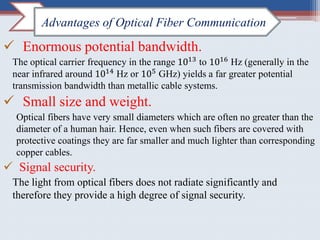
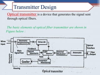

The document discusses the advantages and components of optical fiber communication systems, highlighting benefits such as high bandwidth, light weight, signal security, and low transmission loss. It details the design and function of optical transmitters, including their essential specifications like spectral linewidth and extinction ratio, as well as the roles of different components such as optical sources and modulators. Additionally, it addresses the factors affecting transmission distance in optical systems.