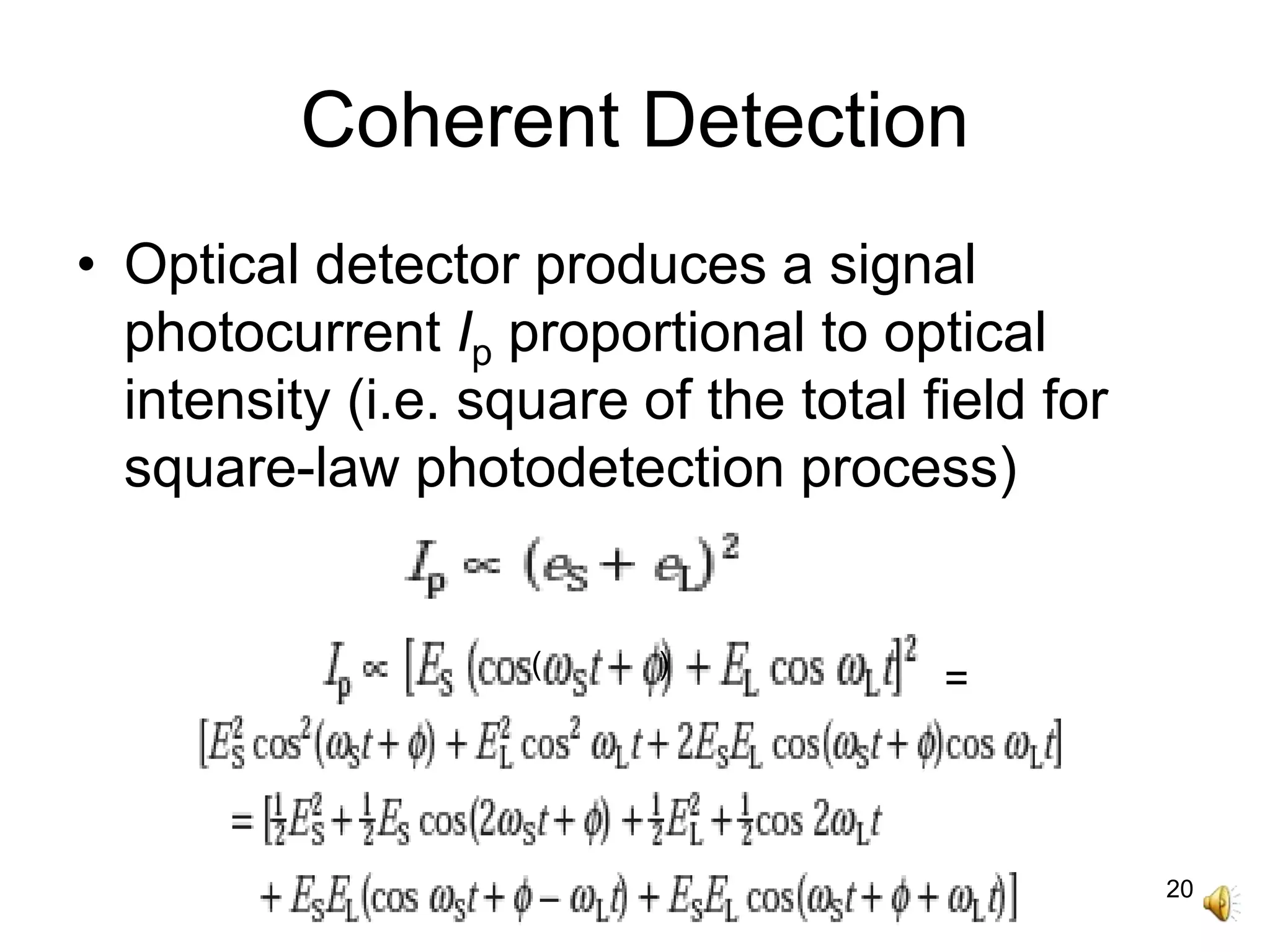
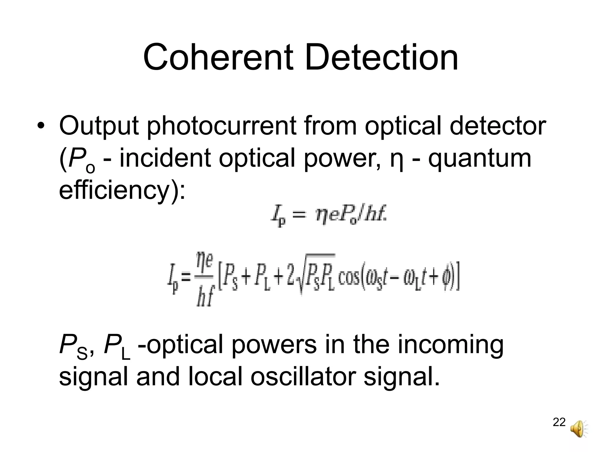
1
Coherent Systems
MEC
2
Contents
• Introduction.
• Coherent System Block Diagram.
• Coherent Receiver Model.
• Modulation Schemes.
• Intradyne and Homodyne Detection.
• Heterodyne Detection.
• Noise and SNR.
3
IM-DD
• IM-DD (direct detection of intensity-
modulated optical carrier) a photon counting
process.
• Each detected photon converted into
electron–hole pair or a number of pairs in
APD due to avalanche gain.
• Optical signal converted directly to a
demodulated electrical output.
• Phase & polarization of electromagnetic
carrier ignored.
4
IM-DD
• Uses currently available optical
components.
• Limited by noise generated in detector and
preamplifier except at very high SNRs.
• Reduced sensitivity of the square-law
detection systems below the fundamental
quantum noise limit by at least 10 to 20 dB.
• Improvements in receiver sensitivity with
wavelength selectivity obtained using well
known coherent detection techniques.
5
Coherent Systems
• Nonlinear mixing between information-
carrying signal and a locally generated
signal.
• Homodyne and Heterodyne detection.
• New signal for heterodyne detection, the
intermediate frequency (IF) appears at a
microwave frequency range.
• IF as difference between frequencies of
incoming signal and local oscillator.
6
Coherent Systems
• Adds to the incoming optical signal from a
locally generated optical wave prior to
detecting the sum.
• Resulting photocurrent is a replica of the
original signal, down translated in frequency
from optical domain (around 105 GHz) to
radio domain (up to several GHz).
• Conventional electronic techniques used for
further signal processing and demodulation.
7
Coherent Systems
• Ideal coherent receiver operating at 1.3 to
1.6 μm wavelengths require a signal
energy of only 10 to 20 photons per bit for
a BER of 10−9.
• Benefits high-speed systems operating at
longer wavelengths.
• Improved receiver sensitivity (5 - 20 dB)
and SNR, increased repeater spacing.
• Permits WDM of huge channel numbers.
8
Coherent System Advantages
• Increased repeater spacing for inland and
undersea transmission systems.
• Higher transmission rates over existing
routes without reducing repeater spacing.
• Increased power budgets to compensate
for losses at couplers & optical multiplexer
/ demultiplexer devices.
• Improved sensitivity to optical test
equipments.
9
Coherent System Block Diagram
10
Coherent System Blocks
• Transmitter:
- CW narrow-linewidth semiconductor
laser optical frequency oscillator.
- External modulators:
– waveguide devices fabricated from
lithium niobate/III–V compound
semiconductors.
- amplitude/frequency/phase shift keying
of optical carrier by information signal.
11
Modulation Formats
12
Polarization Shift Keying
(PolSK)
• Single-mode optical fiber can support two
polarizations, can be used alternately to
carry a zero or a one.
• Need for active polarization management at
the receiver due to random polarization
changes in standard single-mode fiber.
• Additional receiver complexity for
polarization control, no significant sensitivity
improvement over intensity modulation.
13
Coherent System Blocks
• Receivers:
- Incoming signal combined (or mixed)
with optical output from semiconductor
laser local oscillator.
- Combined signal fed to a photodetector
for direct detection in the conventional
square law device.
14
Homodyne Detection
• Homodyne mode:
- optical frequencies (or wavelengths) of
incoming signal and local oscillator laser
output are identical.
- synchronous demodulation scheme,
detected signal brought directly to the
baseband, then optical phase estimation is
required.
15
Heterodyne Detection
• Heterodyne mode:
- local oscillator frequency offset from the
incoming signal frequency, electrical
spectrum from the output of the detector
centered on intermediate frequency (IF).
• IF to depend on information transmission
rate and modulation characteristics.
16
Heterodyne Detection
• IF is a difference frequency, contains the
information signal, can be demodulated.
• Can utilize either synchronous or
asynchronous/nonsynchronous detection.
• Synchronous or coherent demodulation -
estimates phase of IF signal in transferring
it to baseband, phase-locking to follow
phase fluctuations in incoming and local
oscillator signals.
17
Coherent Detection
• Low-level incoming signal field eS
combined with a larger local oscillator
laser signal field eL.
ES - peak incoming signal field, ωS - its angular
frequency, EL- peak local oscillator field, ωL - its
angular frequency, øS - incoming signal phase, øL -
local oscillator signal phase.
ø = øS − øL
18
Coherent Detection
• Information contained in the variation of ES
for ASK.
• Heterodyne detection - local oscillator
frequency ωLoffset from incoming signal
frequency ωS by intermediate frequency ωIF.
• Homodyne detection - no offset b/w ωS and
ωL, ωIF = 0, combined signal recovered in
baseband.
19
Coherent Receiver Model
Incoming signal and local oscillator laser
wavefronts to be perfectly matched at the
photodetector surface for ideal coherent
detection.
20
Coherent Detection
• Optical detector produces a signal
photocurrent Ip proportional to optical
intensity (i.e. square of the total field for
square-law photodetection process)
=( )
21
Coherent Detection
• Frequency terms 2ωS and 2ωL are beyond
the response of the detector, do not
appear at the output.
• Optical power contained in a signal is
proportional to square of its electrical field
strength.
22
Coherent Detection
• Output photocurrent from optical detector
(Po - incident optical power, η - quantum
efficiency):
PS, PL -optical powers in the incoming
signal and local oscillator signal.
23
Coherent Detection
• Approximating,
• For heterodyne detection ωS ≠ ωL
• For homodyne detection ωS = ωL
R - responsivity of optical detector
24
Coherent Detection
• Signal photocurrent proportional to √PS
than PS.
• Signal photocurrent effectively amplified
by a factor √PL proportional to the local
oscillator field.
• Increase in optical signal level without
affecting the receiver preamplifier thermal
noise or photodetector dark current noise -
improved receiver sensitivities.
25
Coherent Detection
• Two separate laser sources employed for
signal & local oscillator beams - correlation
to exist between the two signals.
• Single laser source may be used with an
appropriate path length difference as, for
example, when taking measurements by
interferometric techniques.
26
Noise in Coherent Detection
• Analysis applicable for ASK, not for FSK and
PSK.
• When PL >> PS, dominant noise source is the
local oscillator quantum noise.
• Quantum noise may be expressed as shot
noise, mean square shot noise current from
local oscillator,
• Substitute for IpL,
27
Noise in Coherent Detection
• Detected signal power S is the square of
average signal photocurrent,
• When local oscillator power is large,
• Provides shot noise limit for optical
heterodyne detection.
BIF = 2B
28
Homodyne Detection
• Homodyne detection - photodetector
output appears in baseband.
• SNR limit for optical homodyne detection:
• Increased sensitivity, reduced receiver
bandwidth requirements, higher maximum
transmission rate.
29
Receiver Configurations
30
Heterodyne Detection
• Heterodyne detection - a beat-note signal
between incoming optical signal and local
oscillator signal produce IF signal obtained
using square-law optical detector.
• IF signal has a frequency of between three
and four times the transmission rate.
• IF demodulated to baseband using
synchronous or asynchronous detection.
31
Heterodyne Detection
• Optical receiver bandwidth several times
greater than that of a direct detection
receiver required for specific transmission
rate.
• IF frequency fluctuation degrades
heterodyne receiver performance,
frequency stabilization through feed back
from demodulator through automatic
frequency control (AFC) to the local
oscillator drive circuit.
32
Homodyne Detection
• Phase of local oscillator signal locked to
the incoming signal.
• Synchronous detection scheme to be
employed.
• Mixing in the optical detector produces
baseband information signal, requires no
further demodulation.
• AFC loop to provide necessary frequency
stabilization.
33
Intradyne Detection
• Incoming signal not precisely shifted to
baseband as in homodyne detection.
• Shifted to a frequency much lower than
the data transmission rate.
• Slightly wider electronic filtering using a
baseband filter.
• Use of automatic frequency control.
• Use of PLL can be avoided with intradyne
detection, low IF generated, IF not zero as
in homodyne receivers.
34
Spectral Comparison
35
Thank You

Coherent systems

  • 1.
  • 2.
    2 Contents • Introduction. • CoherentSystem Block Diagram. • Coherent Receiver Model. • Modulation Schemes. • Intradyne and Homodyne Detection. • Heterodyne Detection. • Noise and SNR.
  • 3.
    3 IM-DD • IM-DD (directdetection of intensity- modulated optical carrier) a photon counting process. • Each detected photon converted into electron–hole pair or a number of pairs in APD due to avalanche gain. • Optical signal converted directly to a demodulated electrical output. • Phase & polarization of electromagnetic carrier ignored.
  • 4.
    4 IM-DD • Uses currentlyavailable optical components. • Limited by noise generated in detector and preamplifier except at very high SNRs. • Reduced sensitivity of the square-law detection systems below the fundamental quantum noise limit by at least 10 to 20 dB. • Improvements in receiver sensitivity with wavelength selectivity obtained using well known coherent detection techniques.
  • 5.
    5 Coherent Systems • Nonlinearmixing between information- carrying signal and a locally generated signal. • Homodyne and Heterodyne detection. • New signal for heterodyne detection, the intermediate frequency (IF) appears at a microwave frequency range. • IF as difference between frequencies of incoming signal and local oscillator.
  • 6.
    6 Coherent Systems • Addsto the incoming optical signal from a locally generated optical wave prior to detecting the sum. • Resulting photocurrent is a replica of the original signal, down translated in frequency from optical domain (around 105 GHz) to radio domain (up to several GHz). • Conventional electronic techniques used for further signal processing and demodulation.
  • 7.
    7 Coherent Systems • Idealcoherent receiver operating at 1.3 to 1.6 μm wavelengths require a signal energy of only 10 to 20 photons per bit for a BER of 10−9. • Benefits high-speed systems operating at longer wavelengths. • Improved receiver sensitivity (5 - 20 dB) and SNR, increased repeater spacing. • Permits WDM of huge channel numbers.
  • 8.
    8 Coherent System Advantages •Increased repeater spacing for inland and undersea transmission systems. • Higher transmission rates over existing routes without reducing repeater spacing. • Increased power budgets to compensate for losses at couplers & optical multiplexer / demultiplexer devices. • Improved sensitivity to optical test equipments.
  • 9.
  • 10.
    10 Coherent System Blocks •Transmitter: - CW narrow-linewidth semiconductor laser optical frequency oscillator. - External modulators: – waveguide devices fabricated from lithium niobate/III–V compound semiconductors. - amplitude/frequency/phase shift keying of optical carrier by information signal.
  • 11.
  • 12.
    12 Polarization Shift Keying (PolSK) •Single-mode optical fiber can support two polarizations, can be used alternately to carry a zero or a one. • Need for active polarization management at the receiver due to random polarization changes in standard single-mode fiber. • Additional receiver complexity for polarization control, no significant sensitivity improvement over intensity modulation.
  • 13.
    13 Coherent System Blocks •Receivers: - Incoming signal combined (or mixed) with optical output from semiconductor laser local oscillator. - Combined signal fed to a photodetector for direct detection in the conventional square law device.
  • 14.
    14 Homodyne Detection • Homodynemode: - optical frequencies (or wavelengths) of incoming signal and local oscillator laser output are identical. - synchronous demodulation scheme, detected signal brought directly to the baseband, then optical phase estimation is required.
  • 15.
    15 Heterodyne Detection • Heterodynemode: - local oscillator frequency offset from the incoming signal frequency, electrical spectrum from the output of the detector centered on intermediate frequency (IF). • IF to depend on information transmission rate and modulation characteristics.
  • 16.
    16 Heterodyne Detection • IFis a difference frequency, contains the information signal, can be demodulated. • Can utilize either synchronous or asynchronous/nonsynchronous detection. • Synchronous or coherent demodulation - estimates phase of IF signal in transferring it to baseband, phase-locking to follow phase fluctuations in incoming and local oscillator signals.
  • 17.
    17 Coherent Detection • Low-levelincoming signal field eS combined with a larger local oscillator laser signal field eL. ES - peak incoming signal field, ωS - its angular frequency, EL- peak local oscillator field, ωL - its angular frequency, øS - incoming signal phase, øL - local oscillator signal phase. ø = øS − øL
  • 18.
    18 Coherent Detection • Informationcontained in the variation of ES for ASK. • Heterodyne detection - local oscillator frequency ωLoffset from incoming signal frequency ωS by intermediate frequency ωIF. • Homodyne detection - no offset b/w ωS and ωL, ωIF = 0, combined signal recovered in baseband.
  • 19.
    19 Coherent Receiver Model Incomingsignal and local oscillator laser wavefronts to be perfectly matched at the photodetector surface for ideal coherent detection.
  • 20.
    20 Coherent Detection • Opticaldetector produces a signal photocurrent Ip proportional to optical intensity (i.e. square of the total field for square-law photodetection process) =( )
  • 21.
    21 Coherent Detection • Frequencyterms 2ωS and 2ωL are beyond the response of the detector, do not appear at the output. • Optical power contained in a signal is proportional to square of its electrical field strength.
  • 22.
    22 Coherent Detection • Outputphotocurrent from optical detector (Po - incident optical power, η - quantum efficiency): PS, PL -optical powers in the incoming signal and local oscillator signal.
  • 23.
    23 Coherent Detection • Approximating, •For heterodyne detection ωS ≠ ωL • For homodyne detection ωS = ωL R - responsivity of optical detector
  • 24.
    24 Coherent Detection • Signalphotocurrent proportional to √PS than PS. • Signal photocurrent effectively amplified by a factor √PL proportional to the local oscillator field. • Increase in optical signal level without affecting the receiver preamplifier thermal noise or photodetector dark current noise - improved receiver sensitivities.
  • 25.
    25 Coherent Detection • Twoseparate laser sources employed for signal & local oscillator beams - correlation to exist between the two signals. • Single laser source may be used with an appropriate path length difference as, for example, when taking measurements by interferometric techniques.
  • 26.
    26 Noise in CoherentDetection • Analysis applicable for ASK, not for FSK and PSK. • When PL >> PS, dominant noise source is the local oscillator quantum noise. • Quantum noise may be expressed as shot noise, mean square shot noise current from local oscillator, • Substitute for IpL,
  • 27.
    27 Noise in CoherentDetection • Detected signal power S is the square of average signal photocurrent, • When local oscillator power is large, • Provides shot noise limit for optical heterodyne detection. BIF = 2B
  • 28.
    28 Homodyne Detection • Homodynedetection - photodetector output appears in baseband. • SNR limit for optical homodyne detection: • Increased sensitivity, reduced receiver bandwidth requirements, higher maximum transmission rate.
  • 29.
  • 30.
    30 Heterodyne Detection • Heterodynedetection - a beat-note signal between incoming optical signal and local oscillator signal produce IF signal obtained using square-law optical detector. • IF signal has a frequency of between three and four times the transmission rate. • IF demodulated to baseband using synchronous or asynchronous detection.
  • 31.
    31 Heterodyne Detection • Opticalreceiver bandwidth several times greater than that of a direct detection receiver required for specific transmission rate. • IF frequency fluctuation degrades heterodyne receiver performance, frequency stabilization through feed back from demodulator through automatic frequency control (AFC) to the local oscillator drive circuit.
  • 32.
    32 Homodyne Detection • Phaseof local oscillator signal locked to the incoming signal. • Synchronous detection scheme to be employed. • Mixing in the optical detector produces baseband information signal, requires no further demodulation. • AFC loop to provide necessary frequency stabilization.
  • 33.
    33 Intradyne Detection • Incomingsignal not precisely shifted to baseband as in homodyne detection. • Shifted to a frequency much lower than the data transmission rate. • Slightly wider electronic filtering using a baseband filter. • Use of automatic frequency control. • Use of PLL can be avoided with intradyne detection, low IF generated, IF not zero as in homodyne receivers.
  • 34.
  • 35.