Downloaded 200 times
![Formulation of Finite Element Methods
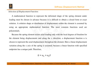
Methods of Weighted Residuals:
The methods of weighted residuals are useful for developing the element equations;
particularly popular is Galerkin’s method. These methods yield the same results as the energy
methods wherever the energy methods are applicable. They are especially useful when a
functional such as potential energy is not readily available. The weighted residual
methods allow the finite element method to be applied directly to any differential equation.
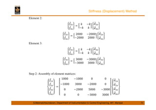
Using any of the methods just outlined will produce the equations to describe the behavior
of an element. These equations are written conveniently in matrix form as
or in compact matrix form as {f} = [k]{d}
S.Meenatchisundaram, Department of Instrumentation Control Engineering, MIT, Manipal 14](https://image.slidesharecdn.com/lecture1112-140909044418-phpapp02/85/Lecture-11-12-14-320.jpg)
![Formulation of Finite Element Methods
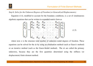
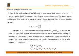
Step 5: Assembly the Element Equations to Obtain the Global or Total Equations and
Introduce Boundary Conditions:
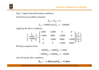
The individual element nodal equilibrium equations generated in step 4 are assembled into
the global nodal equilibrium equations. Another more direct method of superposition (called
the direct stiffness method), whose basis is nodal force equilibrium, can be used to obtain the
global equations for the whole structure. Implicit in the direct stiffness method is the concept
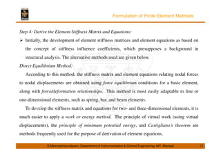
of continuity, or compatibility, which requires that the structure remain together and that no
tears occur anywhere within the structure. The final assembled or global equation written in
matrix form is {F} = [K]{d} (1.4)
S.Meenatchisundaram, Department of Instrumentation Control Engineering, MIT, Manipal 15](https://image.slidesharecdn.com/lecture1112-140909044418-phpapp02/85/Lecture-11-12-15-320.jpg)

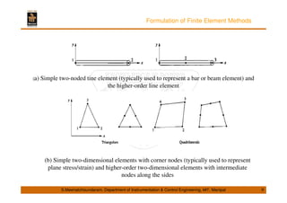
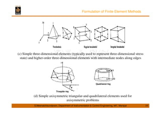
The document discusses finite element methods and their applications in microelectromechanical systems (MEMS). It covers the basic formulation of finite element methods, including discretization, selection of displacement functions, derivation of element stiffness matrices, and assembly of global equations. It also discusses specific applications of finite element analysis to problems in MEMS like heat transfer analysis, thermal stress analysis, and static/modal analysis. The finite element method is well-suited for complex geometries and materials and can model irregular shapes, general loads/boundary conditions, and nonlinear behavior.