This document discusses finite element analysis (FEA) and its applications in engineering. It introduces FEA as a numerical method to determine stress and deflection in structures. It covers FEA modeling techniques including meshing, element types, boundary conditions and assumptions. It also compares traditional design cycles to using FEA and discusses how FEA can replace physical testing.
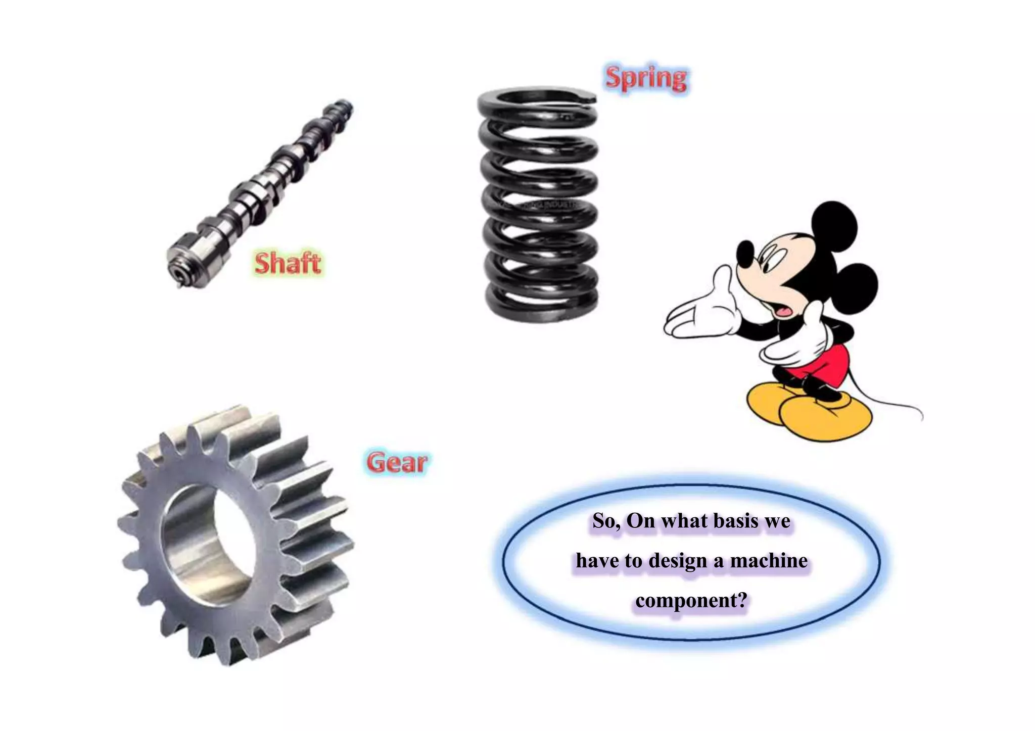
So, On whatbasis we
have to design a machine
component?
4.
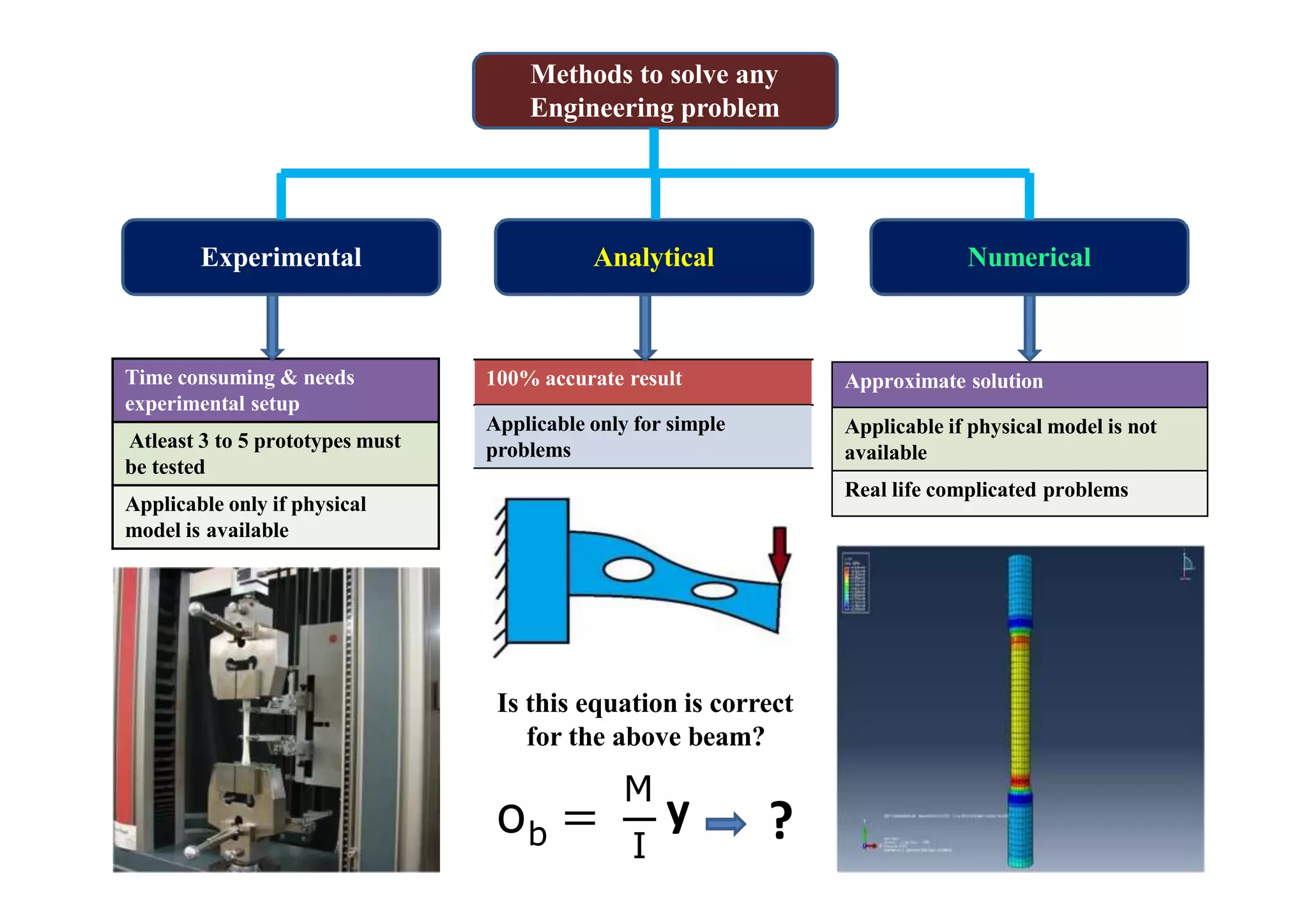
Methods to solveany
Engineering problem
Experimental Analytical Numerical
Time consuming & needs
experimental setup
Atleast 3 to 5 prototypes must
be tested
Applicable only if physical
model is available
Approximate solution
Applicable if physical model is not
available
Real life complicated problems
100% accurate result
Applicable only for simple
problems
bo =
I
M
y ?
Is this equation is correct
for the above beam?
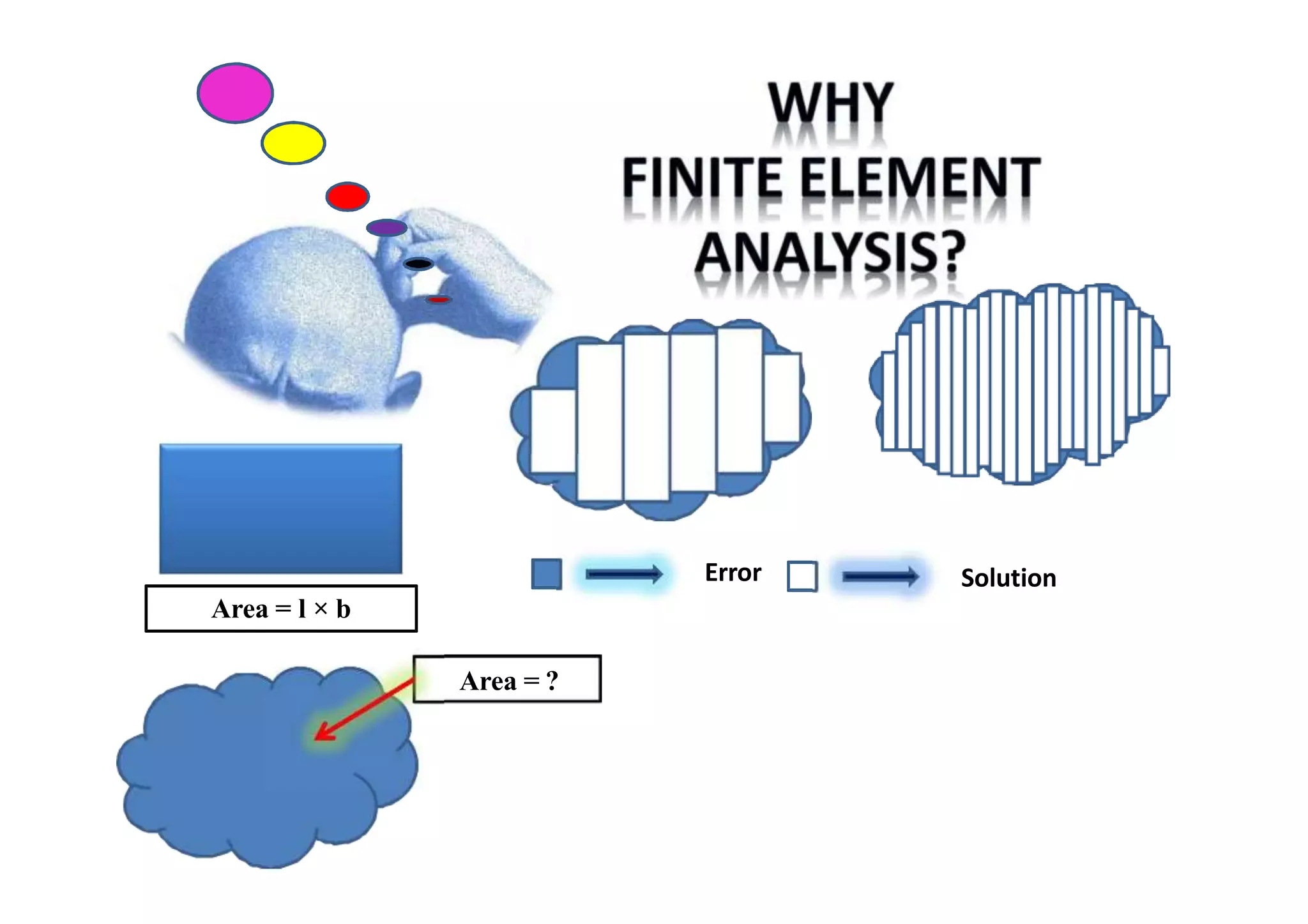
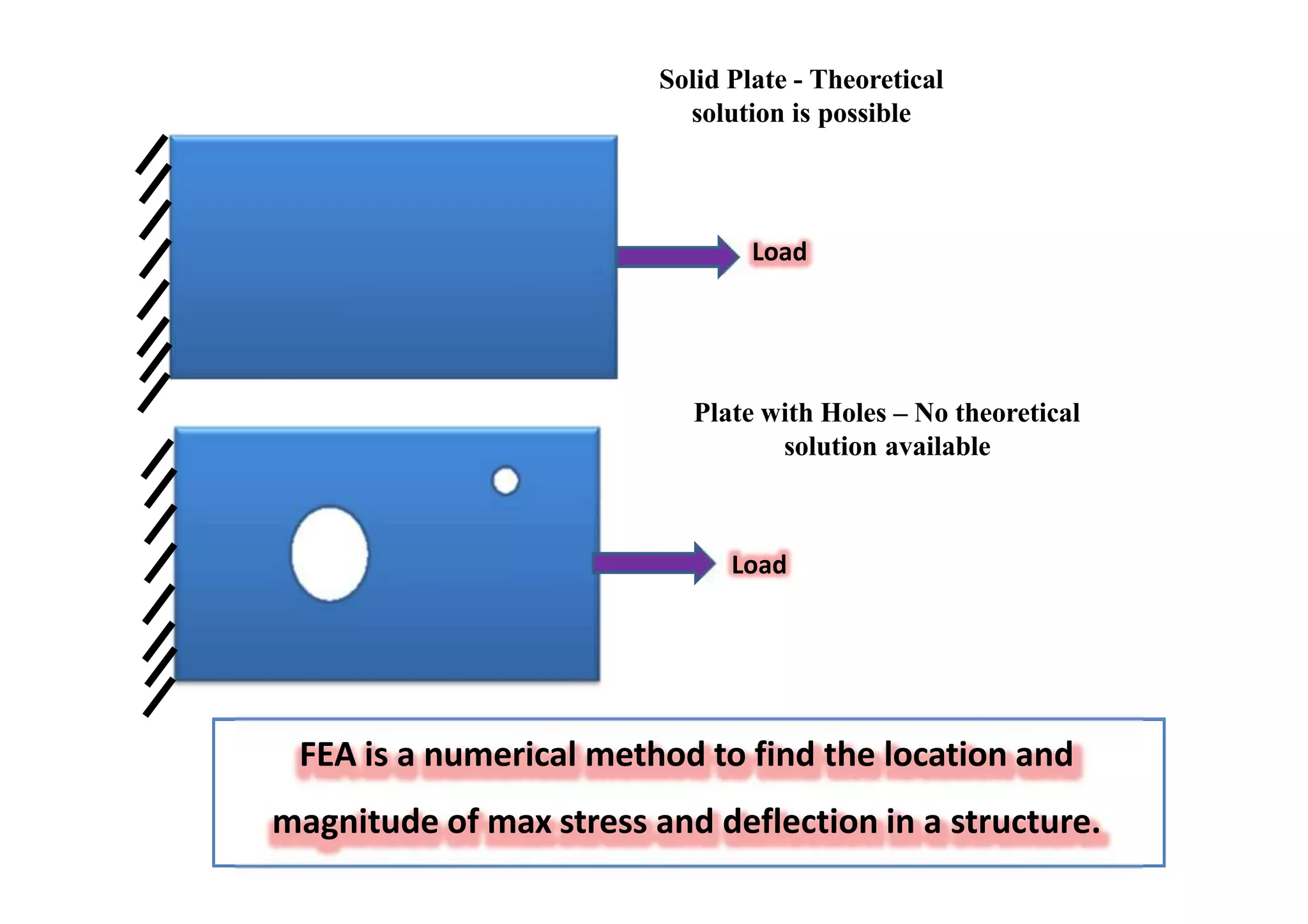
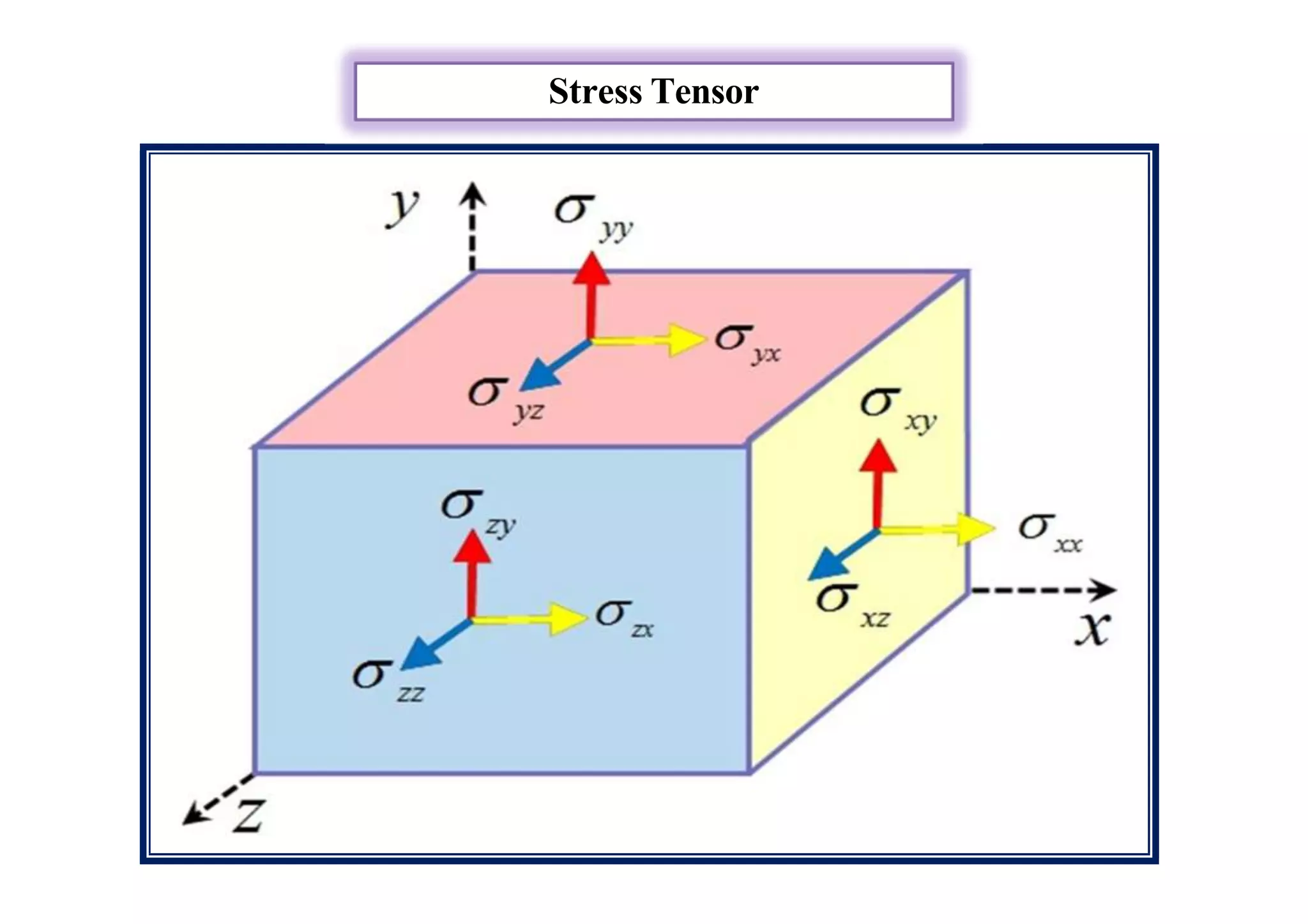
FEA is anumerical method to find the location and
magnitude of max stress and deflection in a structure.
Solid Plate - Theoretical
solution is possible
Load
Plate with Holes – No theoretical
solution available
Load
7.
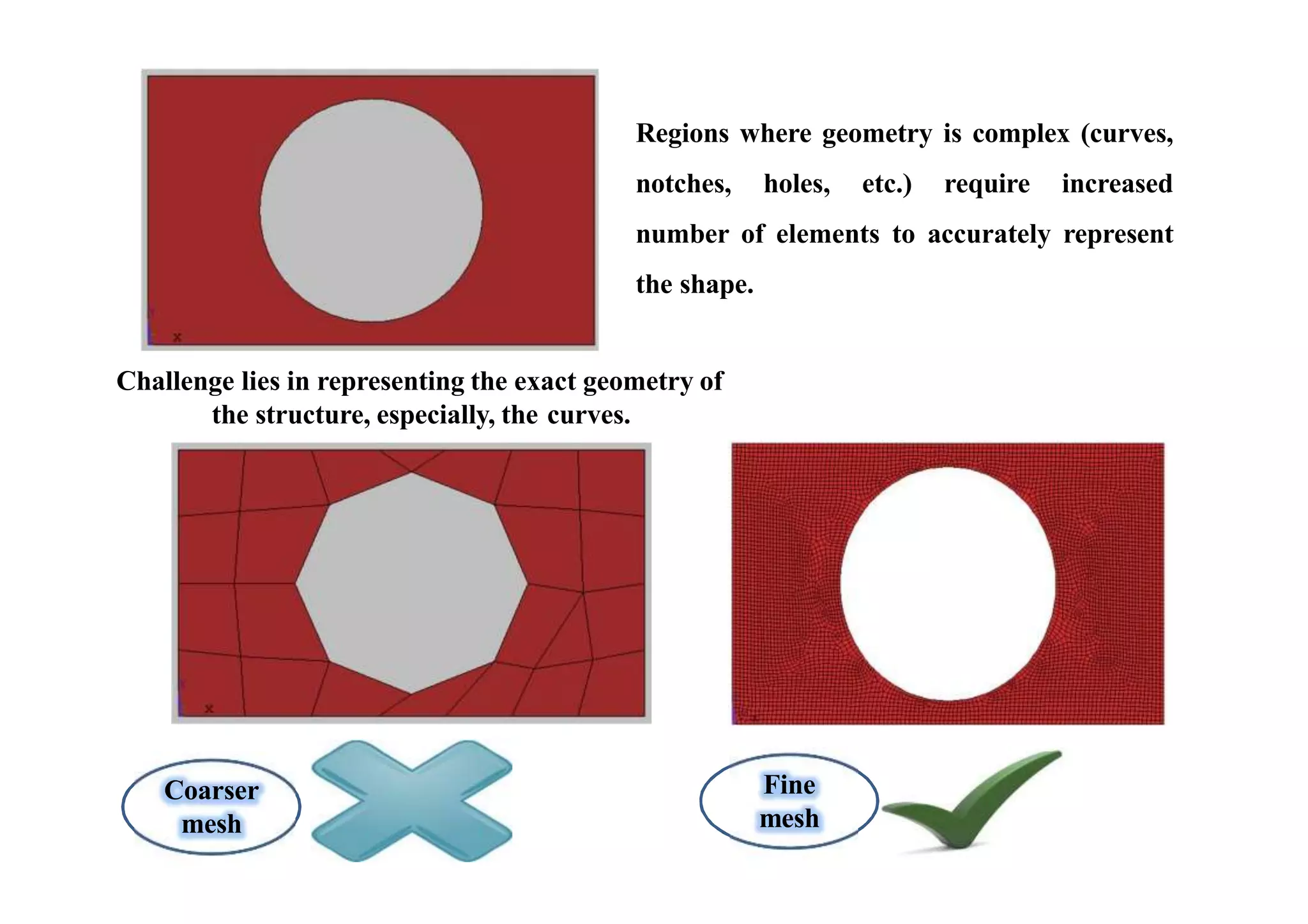
Coarser
mesh
Fine
mesh
Regions where geometryis complex (curves,
notches, holes, etc.) require increased
number of elements to accurately represent
the shape.
Challenge lies in representing the exact geometry of
the structure, especially, the curves.
8.
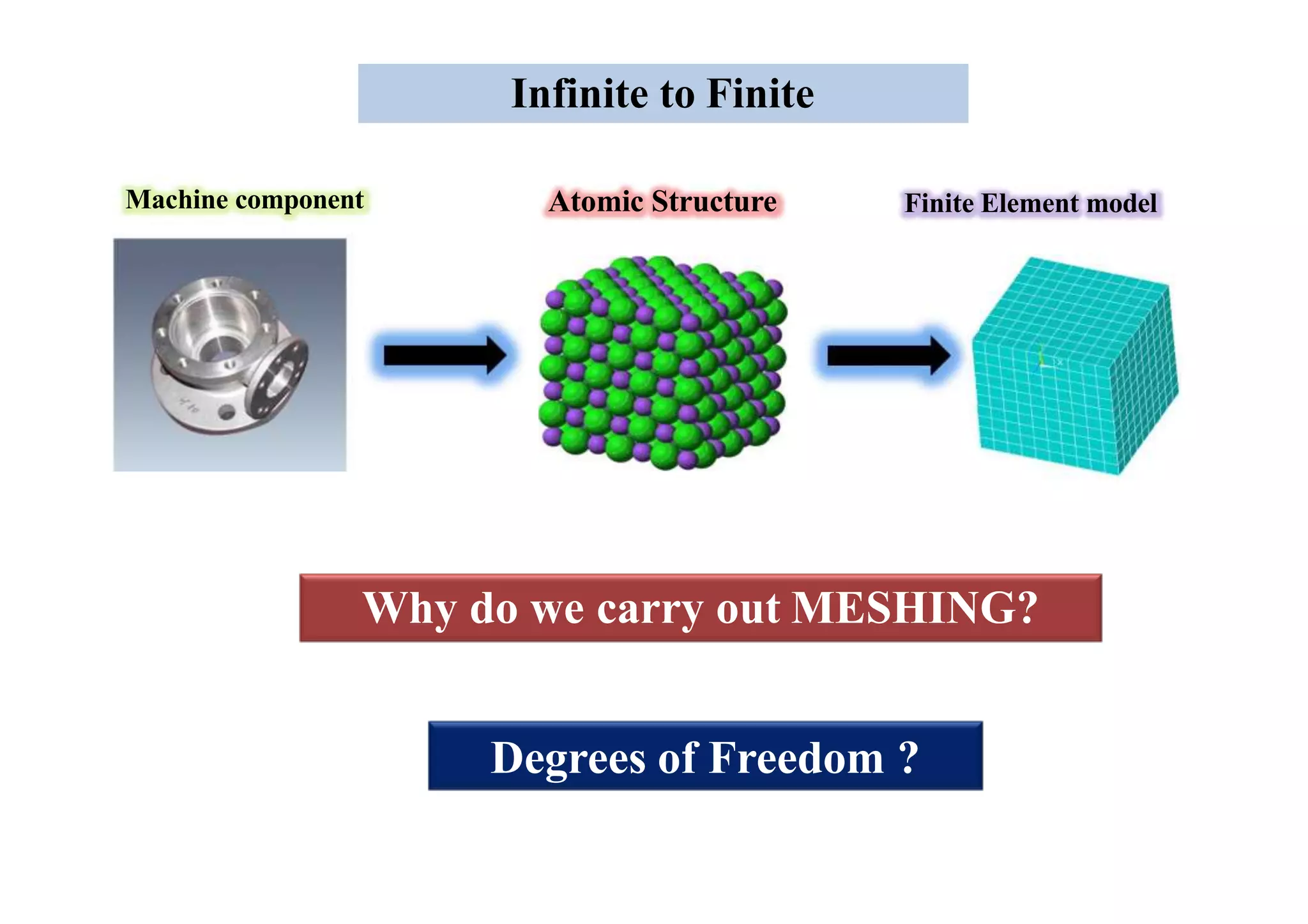
Atomic Structure FiniteElement model
Infinite to Finite
Why do we carry out MESHING?
Degrees of Freedom ?
Machine component
9.
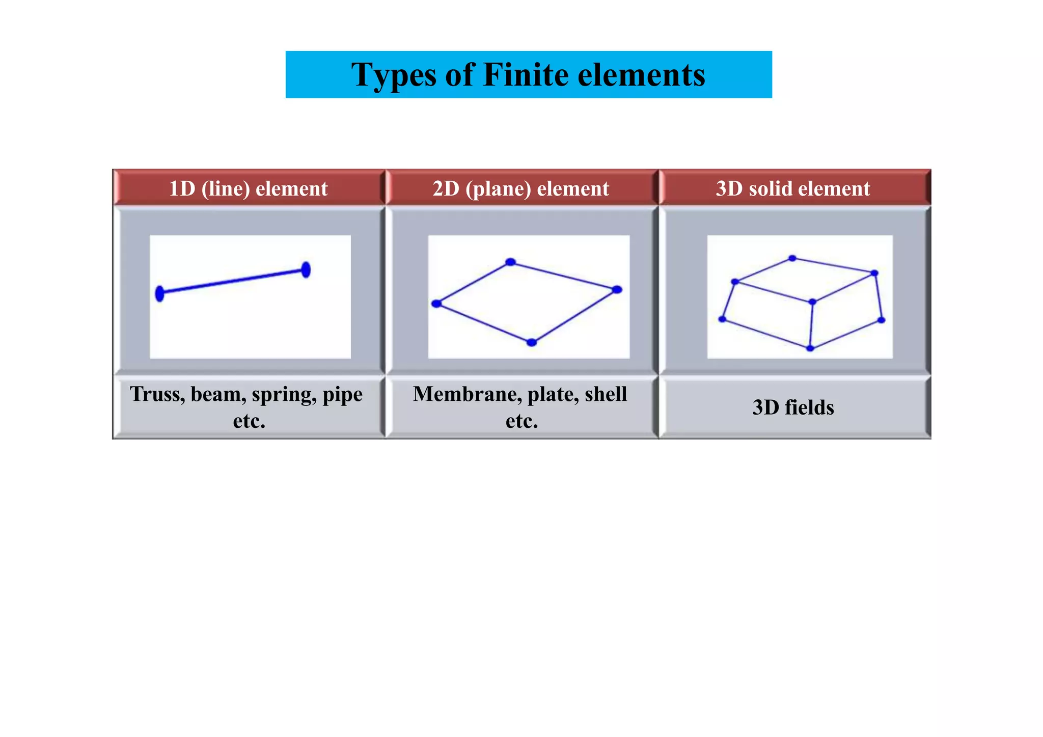
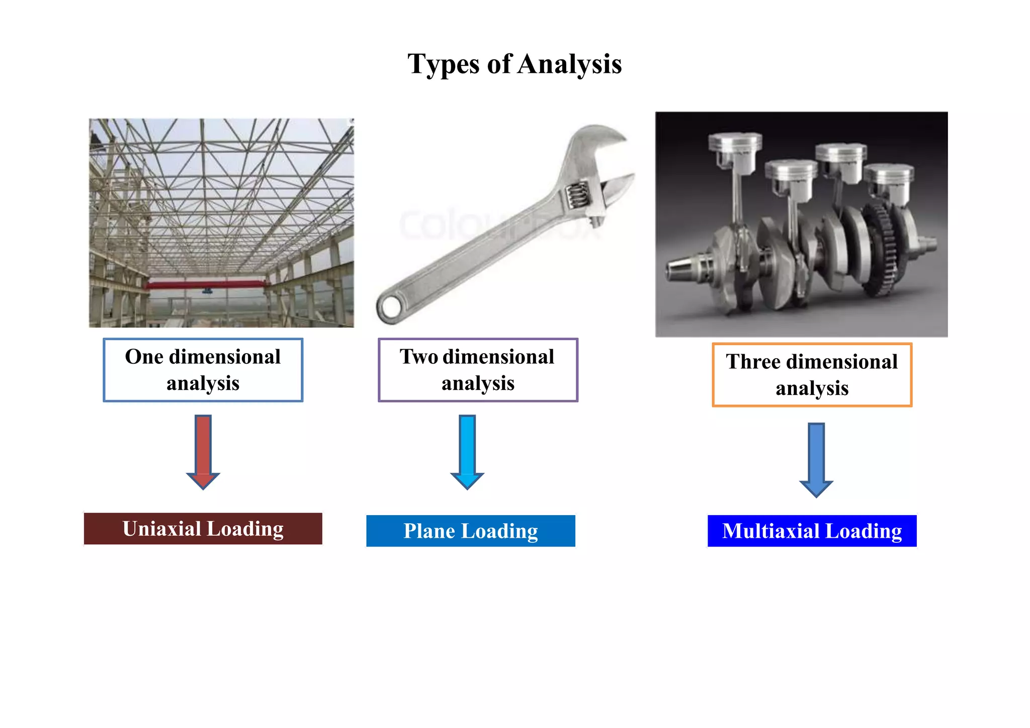
Types of Finiteelements
1D (line) element 2D (plane) element 3D solid element
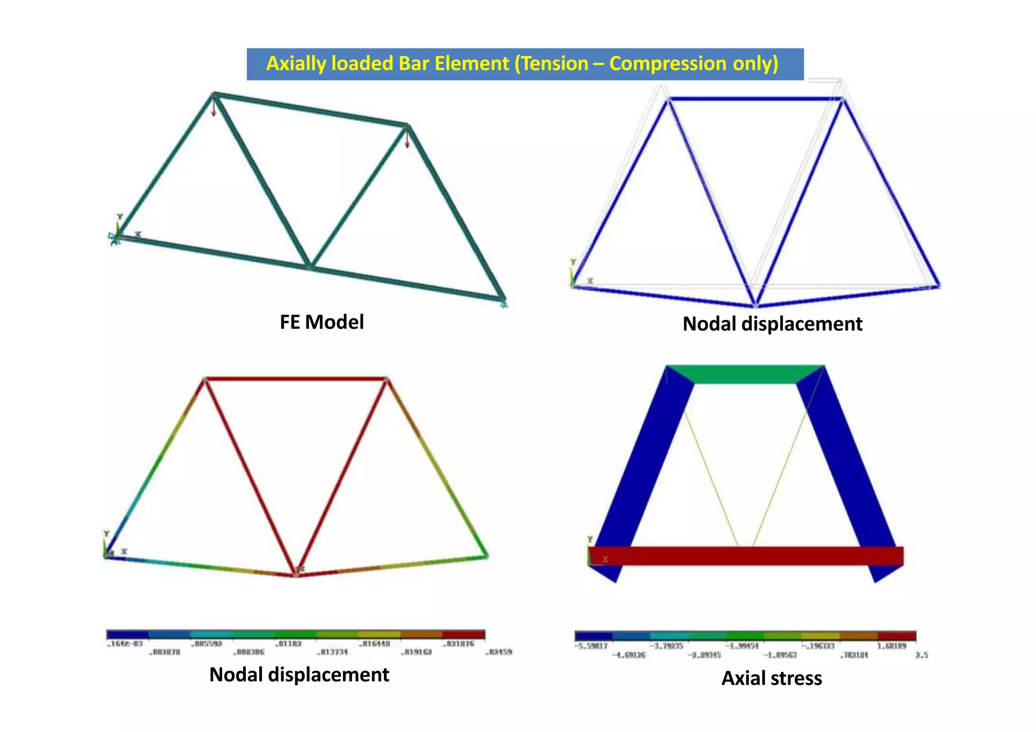
Truss, beam, spring, pipe
etc.
Membrane, plate, shell
etc.
3D fields
10.
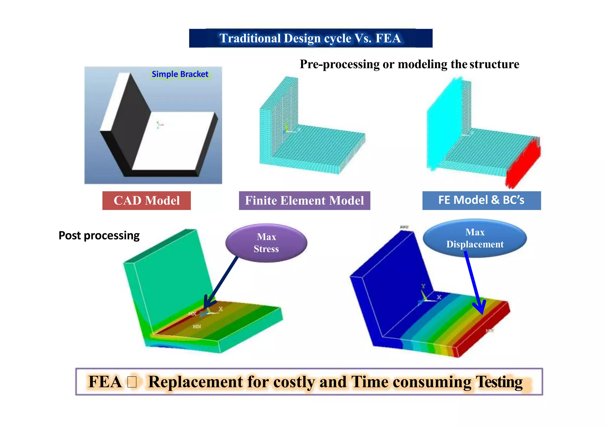
Traditional Design cycleVs. FEA
FE Model & BC’sFinite Element ModelCAD Model
Max
Stress
Max
Displacement
Simple Bracket
FEA Replacement for costly and Time consuming Testing
Pre-processing or modeling thestructure
Post processing
11.
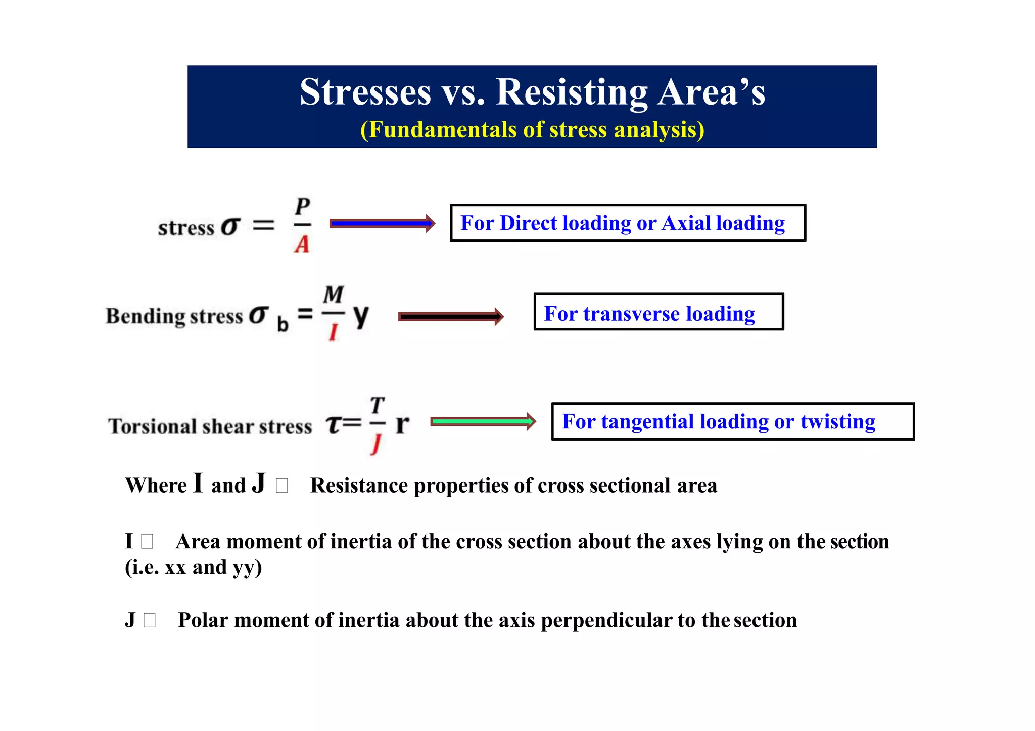
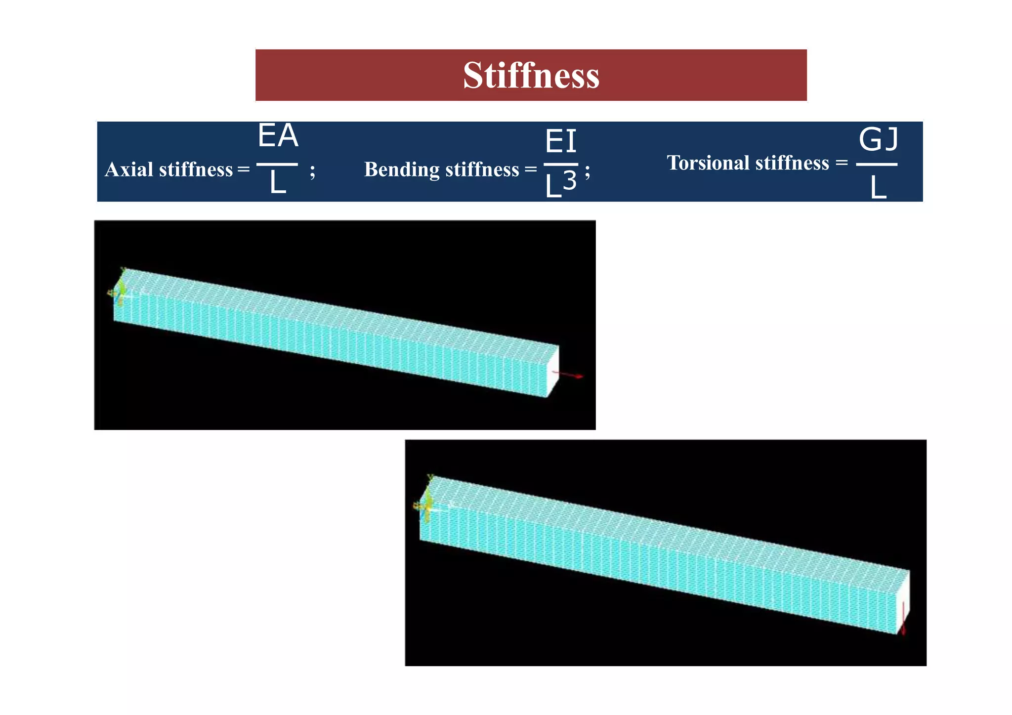
Stresses vs. ResistingArea’s
(Fundamentals of stress analysis)
For Direct loading or Axial loading
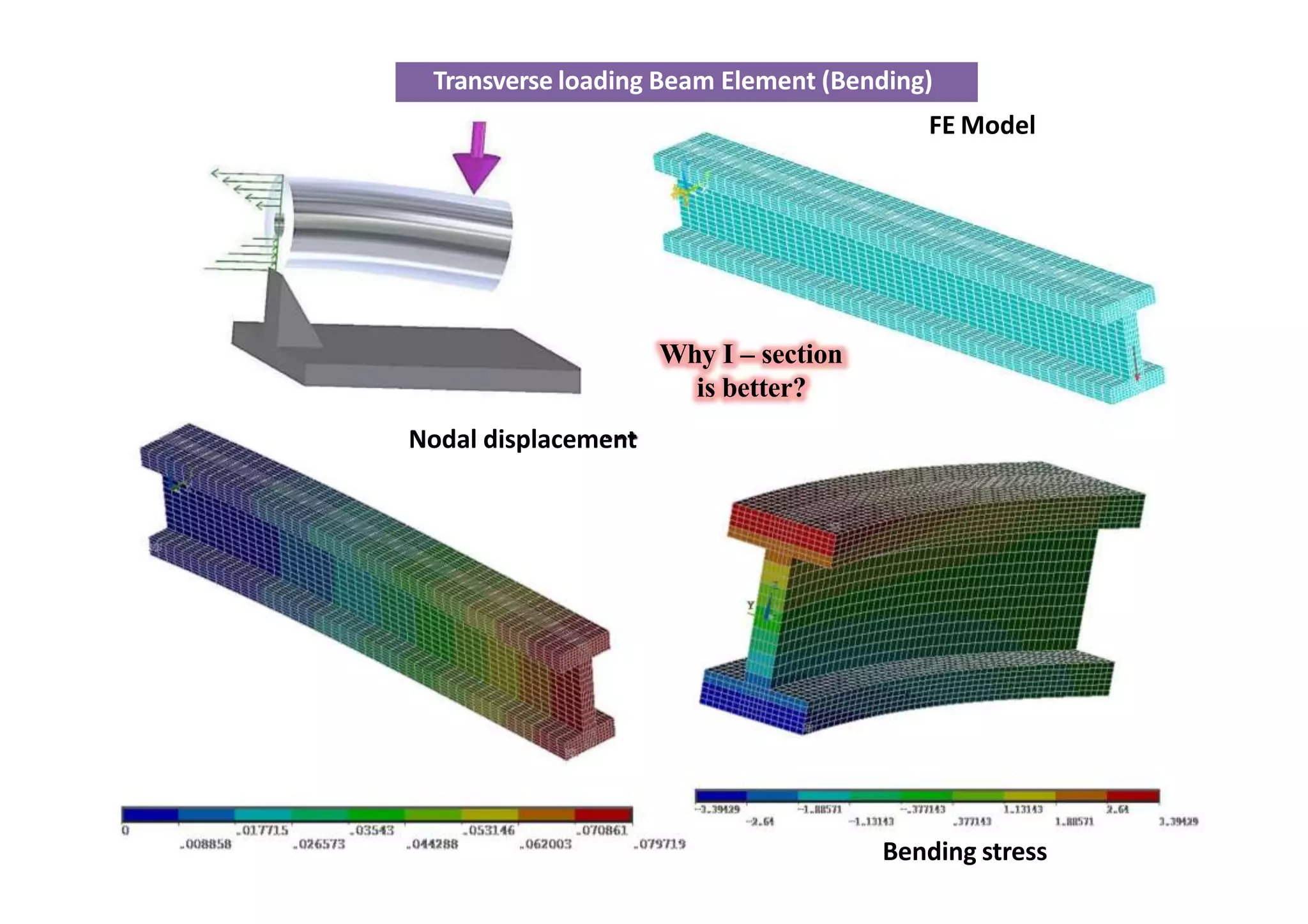
For transverse loading
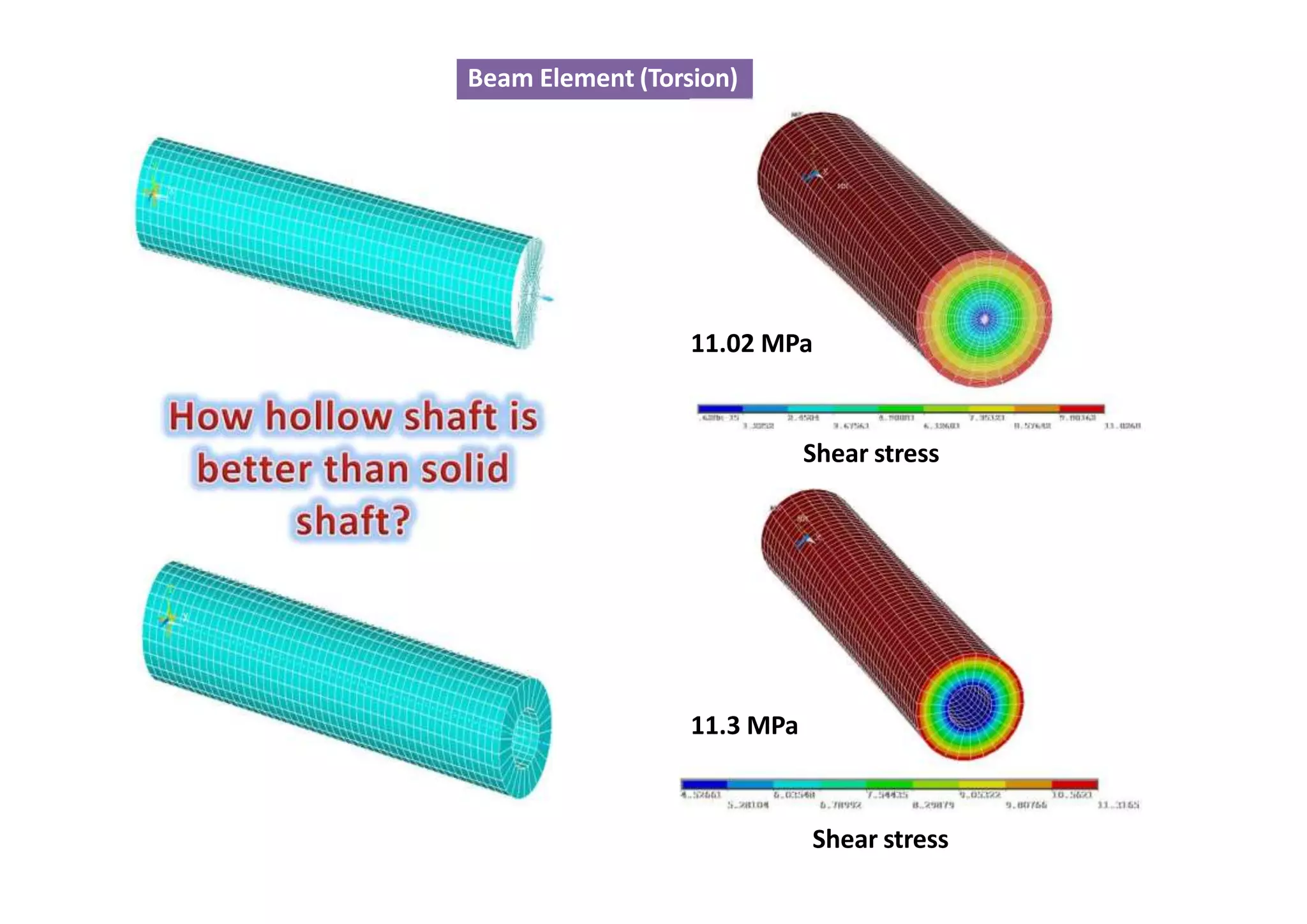
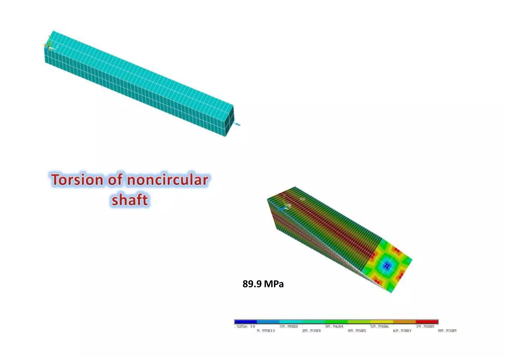
For tangential loading or twisting
Where I and J Resistance properties of cross sectional area
I Area moment of inertia of the cross section about the axes lying on the section
(i.e. xx and yy)
J Polar moment of inertia about the axis perpendicular to thesection
12.
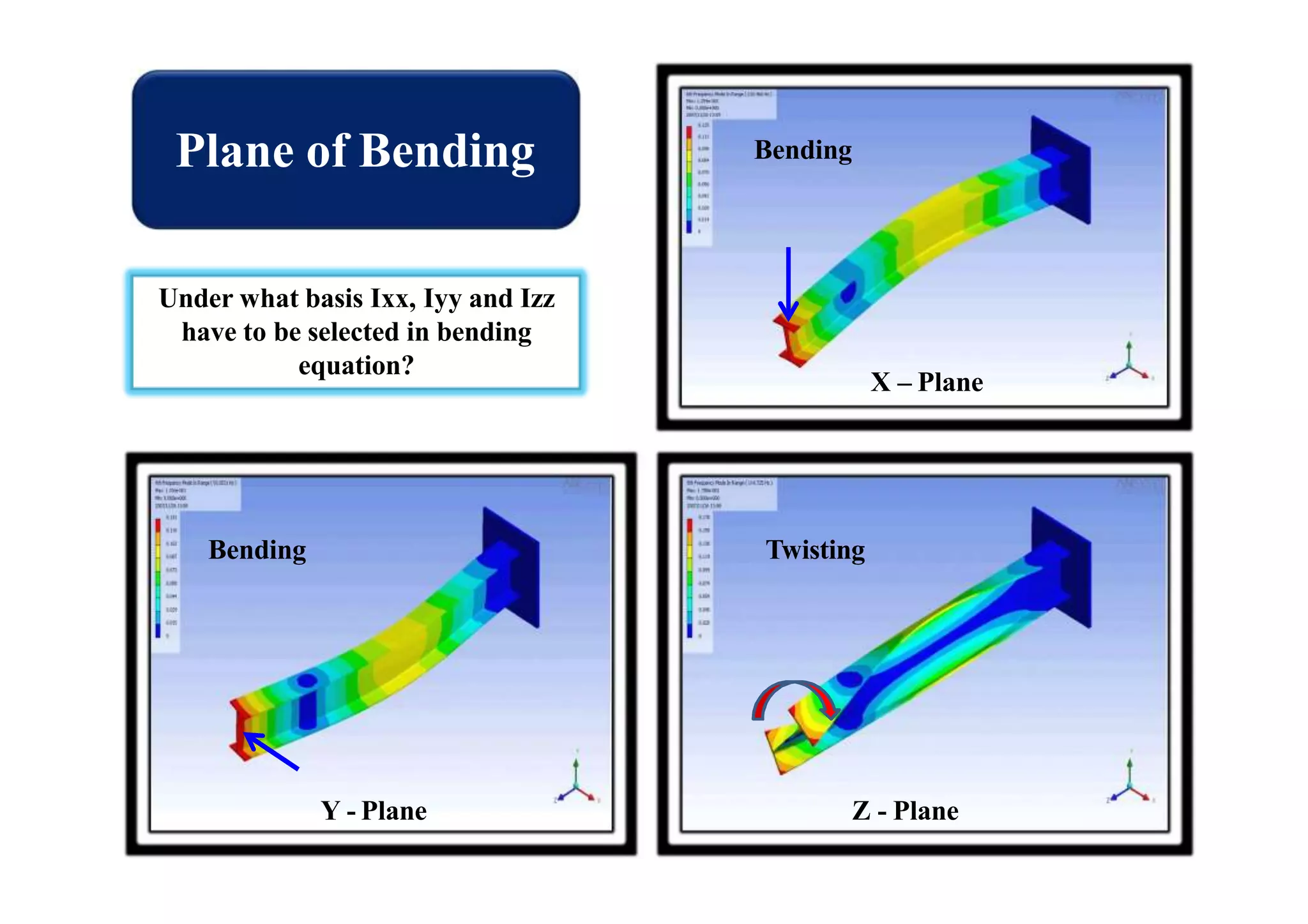
Plane of Bending
X– Plane
Y - Plane Z - Plane
Under what basis Ixx, Iyy and Izz
have to be selected in bending
equation?
Bending
Bending Twisting
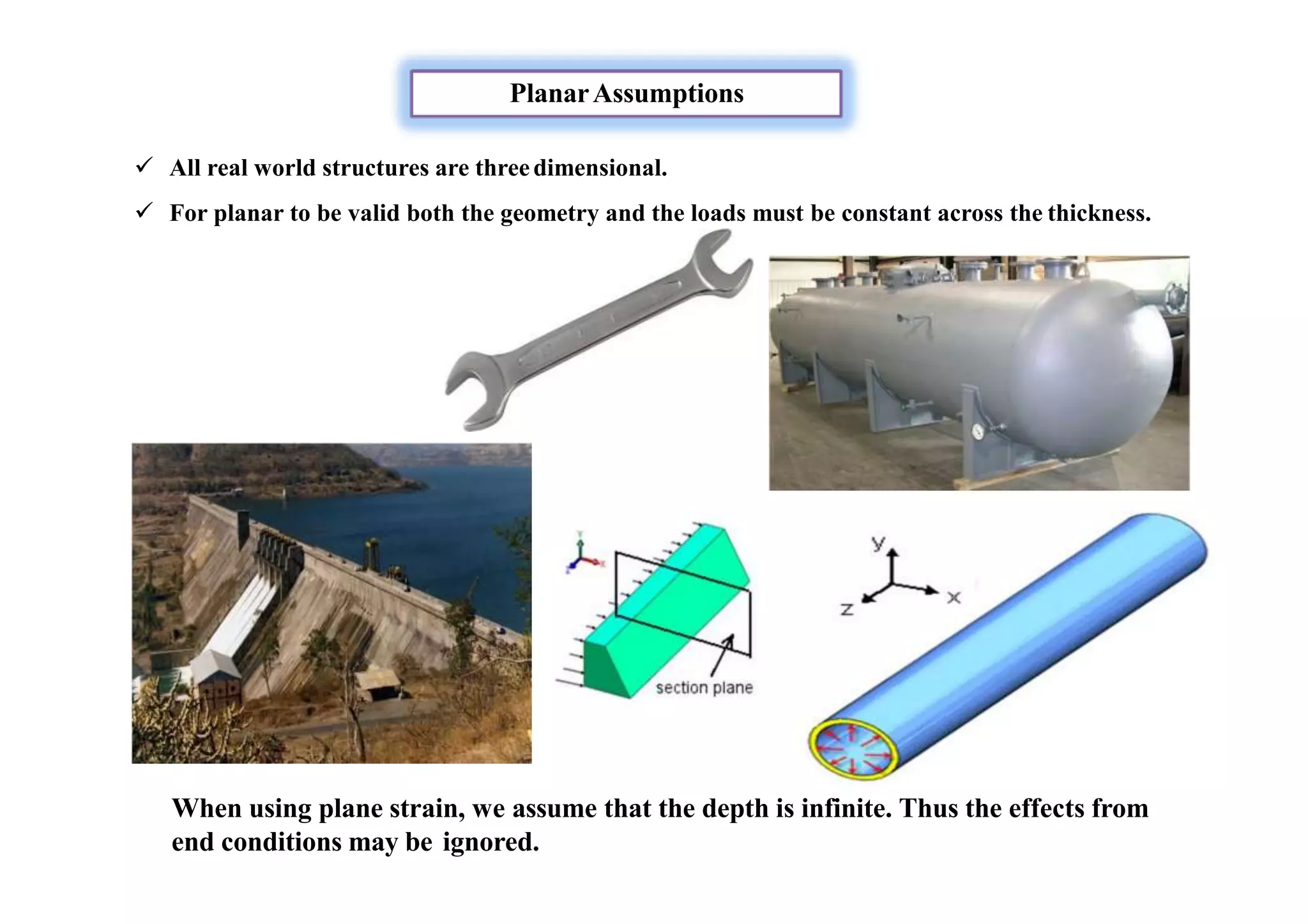
PlanarAssumptions
All realworld structures are threedimensional.
For planar to be valid both the geometry and the loads must be constant across the thickness.
When using plane strain, we assume that the depth is infinite. Thus the effects from
end conditions may be ignored.
15.
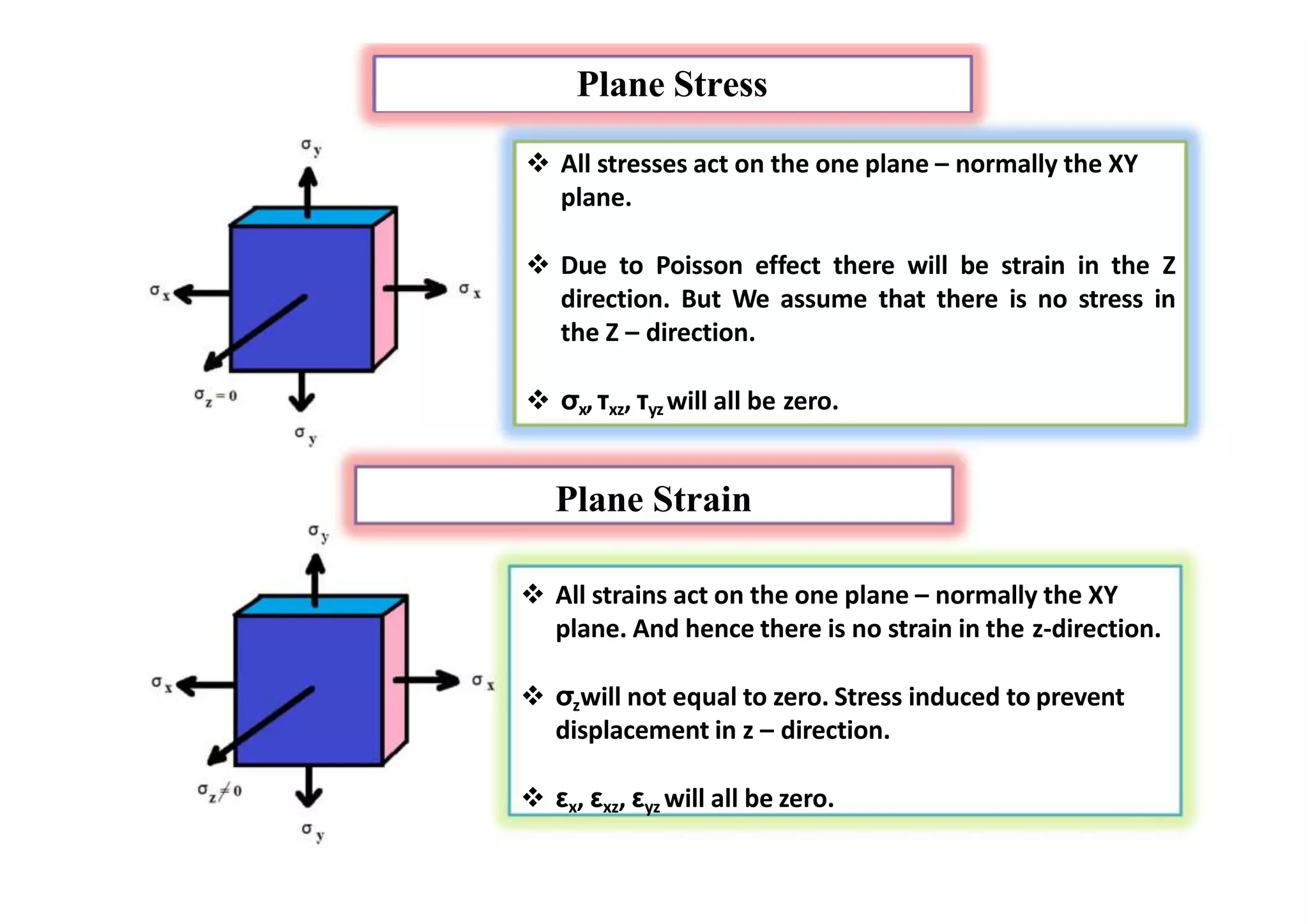
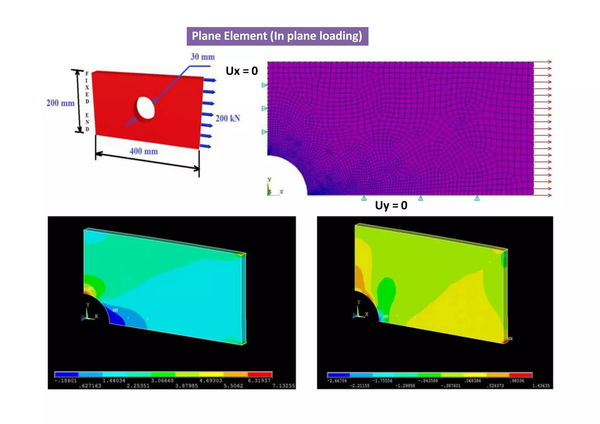
Plane Stress
Allstresses act on the one plane – normally the XY
plane.
Due to Poisson effect there will be strain in the Z
direction. But We assume that there is no stress in
the Z – direction.
σx,τxz, τyz will all be zero.
Plane Strain
All strains act on the one plane – normally the XY
plane. And hence there is no strain in the z-direction.
σzwill not equal to zero. Stress induced to prevent
displacement in z – direction.
εx, εxz, εyz will all be zero.
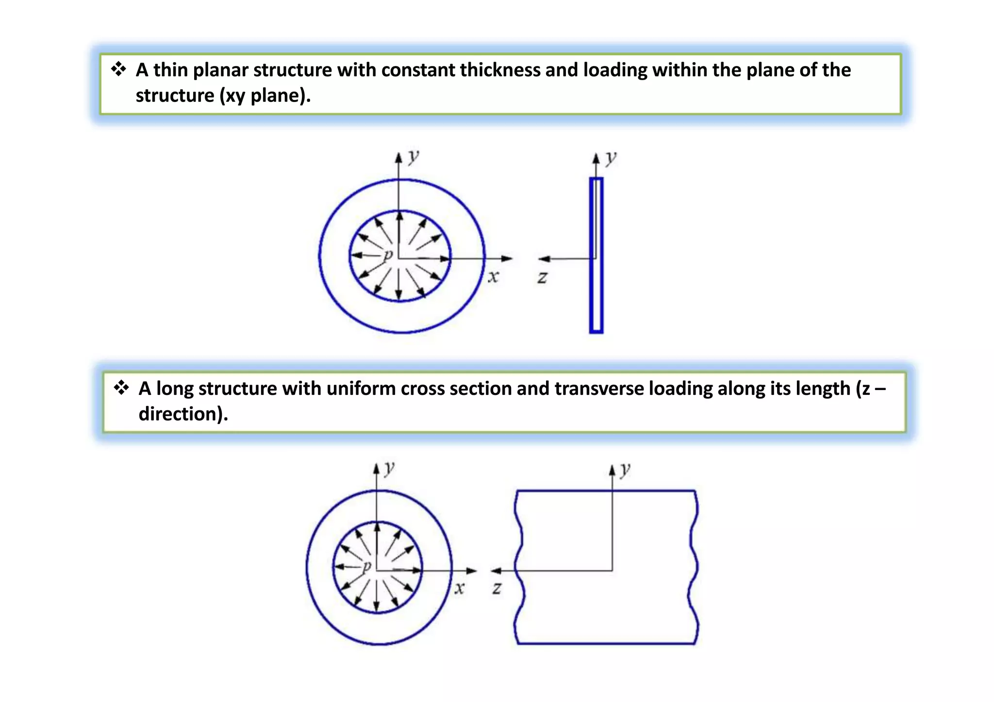
16.
A thinplanar structure with constant thickness and loading within the plane of the
structure (xy plane).
A long structure with uniform cross section and transverse loading along its length (z –
direction).
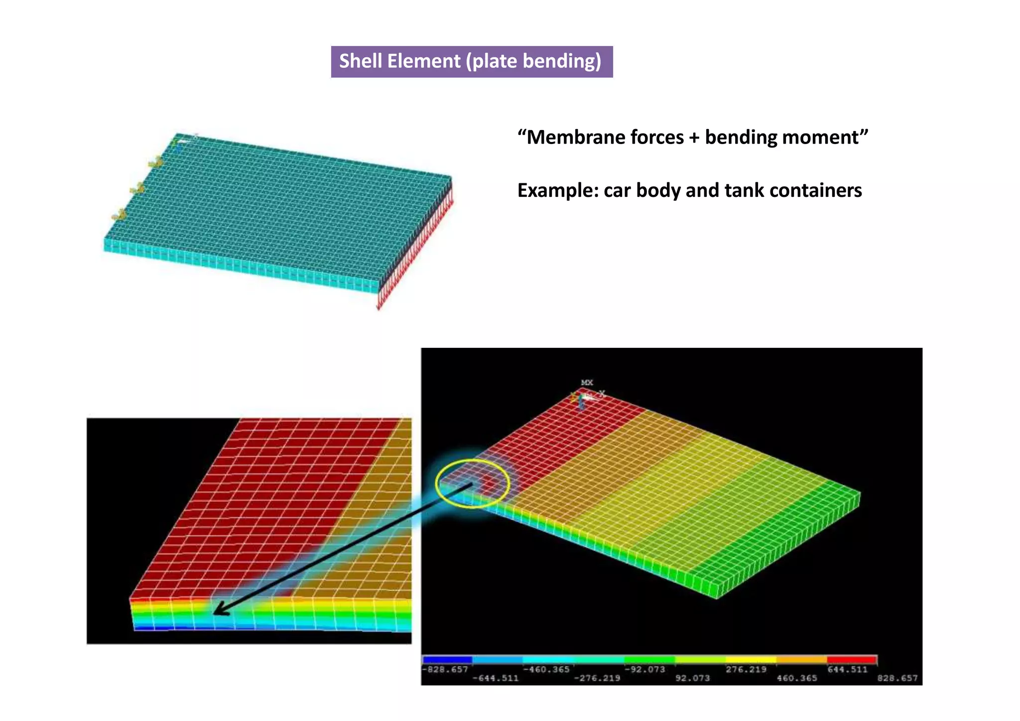
Shell Element (platebending)
“Membrane forces + bending moment”
Example: car body and tank containers
26.
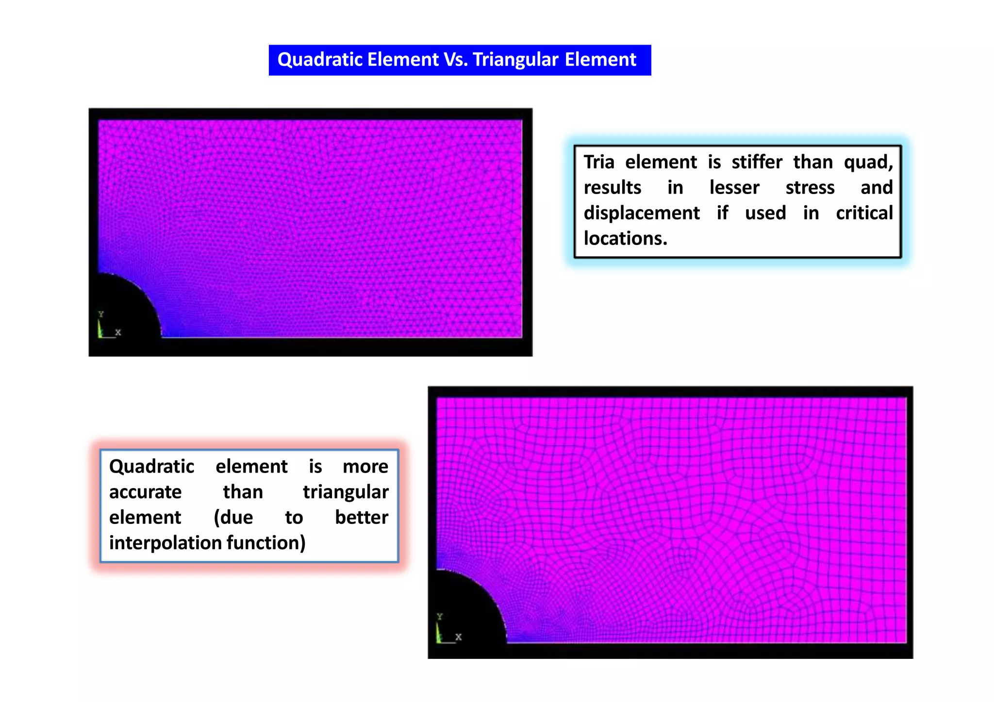
Quadratic Element Vs.Triangular Element
elementQuadratic
accurate than
is more
triangular
betterelement (due to
interpolation function)
Tria element is stiffer than quad,
results in lesser stress and
displacement if used in critical
locations.