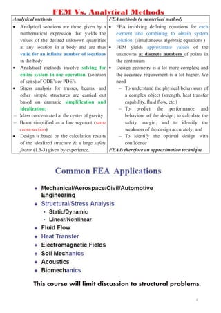
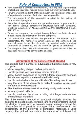
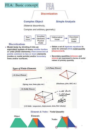
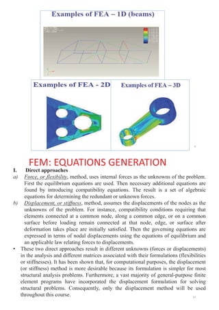
This document outlines the course structure and content for ECE 2408 Theory of Structures V. The course introduces finite element methods for structural analysis. It covers matrix analysis of structures, force and deformation methods, and the use of finite element analysis software. The document compares analytical and finite element analysis methods and explains the key steps in finite element modeling and analysis, including discretization, deriving element stiffness matrices, assembling the global stiffness matrix, applying boundary conditions, and solving for displacements, strains and stresses. The course aims to provide students with skills in using finite element analysis for structural design and problem solving.
The document discusses finite element methods and their applications in microelectromechanical systems (MEMS). It covers the basic formulation of finite element methods, including discretization, selection of displacement functions, derivation of element stiffness matrices, and assembly of global equations. It also discusses specific applications of finite element analysis to problems in MEMS like heat transfer analysis, thermal stress analysis, and static/modal analysis. The finite element method is well-suited for complex geometries and materials and can model irregular shapes, general loads/boundary conditions, and nonlinear behavior.
1) Finite element analysis is a numerical method used to solve engineering problems by breaking structures down into small discrete elements. It involves modeling structures as assemblies of simple geometric shapes called finite elements.
2) The key steps in finite element analysis include discretizing the structure into elements, selecting element types, defining displacement and strain/stress relationships within each element, deriving the element stiffness matrix, and assembling individual element equations into a system of equations for the overall structure.
3) Common approaches include the displacement method, which uses nodal displacements as unknowns, and the force method, which uses internal forces. The displacement method is typically more suitable for computational analysis.
Topics to be discussed-
Introduction
How Does FEM Works?
Types Of Engineering Analysis
Uses of FEM in different fields
How can the FEM Help the Design Engineer?
How can the FEM Help the Design Organization?
Basic Steps & Phases Involved In FEM
Advantages and disadvantages
The Future Scope
References.
The document discusses the finite element method (FEM). FEM is a numerical technique used to find approximate solutions to partial differential equations. It divides a complex problem into small, simpler elements that are solved using relations between each other. There are three phases: pre-processing to mesh the geometry and apply properties/conditions, solution to derive equations and solve for quantities, and post-processing to validate solutions. FEM can model various problem types like static, dynamic, structural, vibrational, and heat transfer analyses. It has advantages like handling complex geometries and loadings but also disadvantages like requiring approximations and computational resources.
The document provides an introduction to finite element methods. It discusses how finite element analysis (FEA) is used to solve complex engineering problems that cannot be solved through closed-form analytical methods. The key steps of FEA include discretizing the domain into finite elements, deriving element equations, assembling equations into a global system of equations, and solving the system of equations. Common element types include line, triangular, and brick elements. The accuracy of FEA depends on factors like element size and shape, approximation functions, and numerical integration.
The document provides an introduction to finite element methods. It discusses how finite element analysis (FEA) is used to solve engineering and science problems involving complex geometries and conditions. FEA works by dividing a body into finite elements and approximating variable fields within each element. This discretization process sets up algebraic equations that approximate the continuous solution. FEA can model problems with complex shapes, loads, materials and include time-dependent effects. It has advantages over closed-form solutions and its accuracy can be improved by refining the mesh. Examples of 1D and 2D elements and approximations are presented.
INTRODUCTION TO FINITE ELEMENT ANALYSISAchyuth Peri
Finite element analysis (FEA) is a numerical technique used to find approximate solutions to partial differential equations. It involves dividing a system into small elements and solving for variables within each element. This allows for analysis of complex geometries, loadings, and materials. The FEM process includes discretizing the system, selecting functions to approximate the solution, assembling element equations into a global system, applying boundary conditions, and calculating displacements, stresses, and strains. FEA offers advantages like analyzing irregular shapes and nonlinear problems, reducing testing costs, and optimizing designs.
Finite element method have many techniques that are used to design the structural elements like automobiles and building materials as well. we use different design software to get our simulated results at ansys, pro-e and matlab.we use these results for our real value problems.
Beams on Elastic Foundation using Winkler Model.docxAdnan Lazem
This document appears to be a student project on analyzing beams on elastic foundations using the stiffness method. It includes chapters on introductions, literature review, theory, a computer program, and conclusions. The literature review discusses previous work on stiffness matrix methods and elastic foundation models dating back to the 1860s. It outlines some of the early development of these methods and key researchers who contributed to their advancement. The document will analyze beams on elastic foundations using the stiffness matrix method and Winkler elastic foundation model.
This document provides an overview of basic linear static finite element analysis (FEA). It defines key terms related to FEA and outlines important assumptions of linear static analysis. It also describes different types of linear static analysis (3D, planar, axisymmetric, etc.) and discusses modeling considerations such as applying boundary conditions and utilizing symmetry. The document is intended to help readers familiar with statics and mechanics of materials better understand how to apply FEA to engineering problems.
The document provides an overview of the history and basics of finite element analysis (FEA). It discusses how FEA was first developed in 1943 and expanded in the following decades. The basics section describes common FEA applications, basic steps which include converting differential equations to algebraic equations, element types, boundary conditions including loads and constraints, and pre-processing, solving, and post-processing steps. Key element types are also summarized.
The document provides an introduction to finite element analysis. It discusses the need for computational methods to solve problems involving complex geometries and boundary conditions that cannot be solved through closed-form analytical methods. The finite element method is introduced as a numerical technique that involves discretizing a continuous domain into discrete subdomains called elements, and approximating variations in dependent variables within each element. This allows setting up algebraic equations that can be solved to approximate the continuous solution. Advantages of the finite element method include its ability to model complex shapes and behaviors, and refine solutions through mesh refinement. Basic concepts such as element types, discretization, and derivation of element equations are described.
Unit I fdocuments.in_introduction-to-fea-and-applications.pptAdityaChavan99
The document provides an introduction to finite element analysis (FEA) and its applications to engineering problems. It discusses that FEA is a numerical method used to solve problems that cannot be solved analytically due to complex geometry or materials. It involves discretizing a continuous structure into small, well-defined substructures called finite elements. The key steps in FEA include preprocessing such as defining geometry, meshing and material properties, solving the problem, and postprocessing results such as stresses and strains. The document also discusses various element types, assembly of elements, sources of error in FEA, and its advantages such as handling complex geometry, loading and materials.
The Finite Element Method (FEM) is a numerical technique for solving problems of engineering and mathematical physics. It subdivides a large problem into smaller, simpler parts that are called finite elements. FEM allows for complex geometries and loading conditions to be modeled. The process involves discretizing the domain into elements, deriving the governing equations for each element, assembling the element equations into a global system of equations, and solving the system to obtain the unknown variable values. FEM can handle a wide range of problems including nonlinear problems and transient problems.
The document provides an introduction to finite element analysis (FEA) including:
1) FEA involves discretizing a continuous structure into small substructures called finite elements connected at nodes. This process is called meshing.
2) The finite element method has three main phases - preprocessing (defining geometry, materials, mesh), solution (solving equations to obtain nodal results), and postprocessing (obtaining stresses, strains from nodal results).
3) FEA can model complex problems that cannot be solved analytically due to complicated geometry or materials, and is well-suited for solving problems in solid mechanics, heat transfer, and other fields on computers.
The document provides an introduction to the finite element method (FEM). It discusses how FEM can be used to obtain approximate solutions to boundary value problems in engineering. It outlines the general steps involved, including preprocessing (defining the model), solution/processing (computing unknown values), and postprocessing (analyzing results). Examples of FEM applications include structural analysis, fluid flow, heat transfer, and more. The key aspects of FEM include discretizing the domain into simple elements, choosing shape functions to approximate variations within each element, and assembling the element equations into a global system of equations to solve.
The document discusses finite element analysis and provides information on various topics related to it. It begins by listing the three methods of engineering analysis as experimental, analytical, and numerical/approximate methods. It then defines key finite element concepts such as finite element, finite element analysis, common element types, nodes, discretization, and the three phases of finite element method. It also discusses structural and non-structural problems, common methods associated with finite element analysis such as force method and stiffness method, and why polynomials are commonly used for interpolation in finite element analysis.
This document outlines the course objectives and contents for a finite element methods in mechanical design course. The key points are:
1. The course will introduce mathematical modeling concepts and teach how to apply finite element methods (FEM) to solve a range of engineering problems.
2. The content will cover one-dimensional, two-dimensional, and three-dimensional FEM analysis. Solution techniques like inversion methods and dynamic analysis will also be discussed.
3. Applications of FEM include stress analysis, buckling analysis, vibration analysis, heat transfer analysis, and fluid flow analysis for both structural and non-structural problems.
Lecture on Introduction to finite element methods & its contentsMesayAlemuTolcha1
The document provides an overview of the Finite Element Method (FEM) course being taught. It discusses:
1. What FEM is and its common application areas like structural analysis, heat transfer, fluid flow.
2. The main steps in FEM including discretization, selecting interpolation functions, developing element matrices, assembling the global matrix, imposing boundary conditions, and solving equations.
3. Different element types like 1D, 2D, and 3D elements and the use of isoparametric formulations.
4. The history of FEM and how it has evolved from being used on mainframe computers to PCs.
A short introduction presentation about the Basics of Finite Element Analysis. This presentation mainly represents the applications of FEA in the real time world.
This document presents a finite element analysis of a stepped bar subjected to axial loading using MATLAB and ANSYS. It begins with an introduction to finite element analysis and describes how MATLAB and ANSYS can be used to model and analyze engineering problems. The document then outlines the specific procedure used to analyze a stepped bar, including defining the problem, developing the analytical solution, and determining displacements and stresses at nodes. The results obtained from MATLAB and finite element analysis are shown to be similar, while ANSYS results are also close. The document concludes the analysis methods allow solving problems efficiently and with less error compared to manual calculations.
International Journal of Engineering Research and Applications (IJERA) is an open access online peer reviewed international journal that publishes research and review articles in the fields of Computer Science, Neural Networks, Electrical Engineering, Software Engineering, Information Technology, Mechanical Engineering, Chemical Engineering, Plastic Engineering, Food Technology, Textile Engineering, Nano Technology & science, Power Electronics, Electronics & Communication Engineering, Computational mathematics, Image processing, Civil Engineering, Structural Engineering, Environmental Engineering, VLSI Testing & Low Power VLSI Design etc.
This document describes a modified dynamic relaxation (DR) method for modeling multi-cracking in concrete. The standard DR method solves nonlinear static problems by finding the steady-state of a simulated dynamic system, but can converge slowly for problems with non-monotonic responses, like cracking. The modified method introduces two-step damping - first under-damping to propagate motion through the system, then critical damping for fast convergence. It was validated on 3D simulations of concrete beam fracture tests, accurately predicting load-displacement curves and capturing size effects, micro-cracking and non-uniform crack propagation.
This document discusses various techniques for non-linear structural analysis using finite element methods. It covers the differences between linear and non-linear analysis, MATLAB-based truss and push-over analyses, using experimental data to build material models for tensile testing simulations, buckling analysis of a stiffened panel, ultimate strength analysis of a hull girder, and comparing the Smith method and finite element analysis for calculating ultimate strength. The goal is to demonstrate various non-linear analysis methods and validate models using experimental data.
This document discusses sources of error in finite element analysis, including modeling errors due to simplifying assumptions, discretization errors from approximating solutions, and numerical errors from limited computer precision. It provides examples of common mistakes that can cause incorrect results, such as incorrect material properties or insufficient boundary constraints. It also discusses best practices for verifying models, such as element testing, mesh refinement studies, and checking results against analytical solutions or boundary conditions.
Finite Element Analysis Lecture Notes Anna University 2013 Regulation NAVEEN UTHANDI
One of the most Simple and Interesting topics in Engineering is FEA. My work will guide average students to score good marks. I have given you full package which includes 2 Marks and Question Banks of previous year. All the Best
For Guidance : Comment Below Happy to Teach and Learn along with you guys
Rainfall intensity duration frequency curve statistical analysis and modeling...bijceesjournal
Using data from 41 years in Patna’ India’ the study’s goal is to analyze the trends of how often it rains on a weekly, seasonal, and annual basis (1981−2020). First, utilizing the intensity-duration-frequency (IDF) curve and the relationship by statistically analyzing rainfall’ the historical rainfall data set for Patna’ India’ during a 41 year period (1981−2020), was evaluated for its quality. Changes in the hydrologic cycle as a result of increased greenhouse gas emissions are expected to induce variations in the intensity, length, and frequency of precipitation events. One strategy to lessen vulnerability is to quantify probable changes and adapt to them. Techniques such as log-normal, normal, and Gumbel are used (EV-I). Distributions were created with durations of 1, 2, 3, 6, and 24 h and return times of 2, 5, 10, 25, and 100 years. There were also mathematical correlations discovered between rainfall and recurrence interval.
Findings: Based on findings, the Gumbel approach produced the highest intensity values, whereas the other approaches produced values that were close to each other. The data indicates that 461.9 mm of rain fell during the monsoon season’s 301st week. However, it was found that the 29th week had the greatest average rainfall, 92.6 mm. With 952.6 mm on average, the monsoon season saw the highest rainfall. Calculations revealed that the yearly rainfall averaged 1171.1 mm. Using Weibull’s method, the study was subsequently expanded to examine rainfall distribution at different recurrence intervals of 2, 5, 10, and 25 years. Rainfall and recurrence interval mathematical correlations were also developed. Further regression analysis revealed that short wave irrigation, wind direction, wind speed, pressure, relative humidity, and temperature all had a substantial influence on rainfall.
Originality and value: The results of the rainfall IDF curves can provide useful information to policymakers in making appropriate decisions in managing and minimizing floods in the study area.
Null Bangalore | Pentesters Approach to AWS IAMDivyanshu
#Abstract:
- Learn more about the real-world methods for auditing AWS IAM (Identity and Access Management) as a pentester. So let us proceed with a brief discussion of IAM as well as some typical misconfigurations and their potential exploits in order to reinforce the understanding of IAM security best practices.
- Gain actionable insights into AWS IAM policies and roles, using hands on approach.
#Prerequisites:
- Basic understanding of AWS services and architecture
- Familiarity with cloud security concepts
- Experience using the AWS Management Console or AWS CLI.
- For hands on lab create account on [killercoda.com](https://killercoda.com/cloudsecurity-scenario/)
# Scenario Covered:
- Basics of IAM in AWS
- Implementing IAM Policies with Least Privilege to Manage S3 Bucket
- Objective: Create an S3 bucket with least privilege IAM policy and validate access.
- Steps:
- Create S3 bucket.
- Attach least privilege policy to IAM user.
- Validate access.
- Exploiting IAM PassRole Misconfiguration
-Allows a user to pass a specific IAM role to an AWS service (ec2), typically used for service access delegation. Then exploit PassRole Misconfiguration granting unauthorized access to sensitive resources.
- Objective: Demonstrate how a PassRole misconfiguration can grant unauthorized access.
- Steps:
- Allow user to pass IAM role to EC2.
- Exploit misconfiguration for unauthorized access.
- Access sensitive resources.
- Exploiting IAM AssumeRole Misconfiguration with Overly Permissive Role
- An overly permissive IAM role configuration can lead to privilege escalation by creating a role with administrative privileges and allow a user to assume this role.
- Objective: Show how overly permissive IAM roles can lead to privilege escalation.
- Steps:
- Create role with administrative privileges.
- Allow user to assume the role.
- Perform administrative actions.
- Differentiation between PassRole vs AssumeRole
Try at [killercoda.com](https://killercoda.com/cloudsecurity-scenario/)
Software Engineering and Project Management - Introduction, Modeling Concepts...Prakhyath Rai
Introduction, Modeling Concepts and Class Modeling: What is Object orientation? What is OO development? OO Themes; Evidence for usefulness of OO development; OO modeling history. Modeling
as Design technique: Modeling, abstraction, The Three models. Class Modeling: Object and Class Concept, Link and associations concepts, Generalization and Inheritance, A sample class model, Navigation of class models, and UML diagrams
Building the Analysis Models: Requirement Analysis, Analysis Model Approaches, Data modeling Concepts, Object Oriented Analysis, Scenario-Based Modeling, Flow-Oriented Modeling, class Based Modeling, Creating a Behavioral Model.
Discover the latest insights on Data Driven Maintenance with our comprehensive webinar presentation. Learn about traditional maintenance challenges, the right approach to utilizing data, and the benefits of adopting a Data Driven Maintenance strategy. Explore real-world examples, industry best practices, and innovative solutions like FMECA and the D3M model. This presentation, led by expert Jules Oudmans, is essential for asset owners looking to optimize their maintenance processes and leverage digital technologies for improved efficiency and performance. Download now to stay ahead in the evolving maintenance landscape.
Comparative analysis between traditional aquaponics and reconstructed aquapon...bijceesjournal
The aquaponic system of planting is a method that does not require soil usage. It is a method that only needs water, fish, lava rocks (a substitute for soil), and plants. Aquaponic systems are sustainable and environmentally friendly. Its use not only helps to plant in small spaces but also helps reduce artificial chemical use and minimizes excess water use, as aquaponics consumes 90% less water than soil-based gardening. The study applied a descriptive and experimental design to assess and compare conventional and reconstructed aquaponic methods for reproducing tomatoes. The researchers created an observation checklist to determine the significant factors of the study. The study aims to determine the significant difference between traditional aquaponics and reconstructed aquaponics systems propagating tomatoes in terms of height, weight, girth, and number of fruits. The reconstructed aquaponics system’s higher growth yield results in a much more nourished crop than the traditional aquaponics system. It is superior in its number of fruits, height, weight, and girth measurement. Moreover, the reconstructed aquaponics system is proven to eliminate all the hindrances present in the traditional aquaponics system, which are overcrowding of fish, algae growth, pest problems, contaminated water, and dead fish.
Introduction- e - waste – definition - sources of e-waste– hazardous substances in e-waste - effects of e-waste on environment and human health- need for e-waste management– e-waste handling rules - waste minimization techniques for managing e-waste – recycling of e-waste - disposal treatment methods of e- waste – mechanism of extraction of precious metal from leaching solution-global Scenario of E-waste – E-waste in India- case studies.
Applications of artificial Intelligence in Mechanical Engineering.pdfAtif Razi
Historically, mechanical engineering has relied heavily on human expertise and empirical methods to solve complex problems. With the introduction of computer-aided design (CAD) and finite element analysis (FEA), the field took its first steps towards digitization. These tools allowed engineers to simulate and analyze mechanical systems with greater accuracy and efficiency. However, the sheer volume of data generated by modern engineering systems and the increasing complexity of these systems have necessitated more advanced analytical tools, paving the way for AI.
AI offers the capability to process vast amounts of data, identify patterns, and make predictions with a level of speed and accuracy unattainable by traditional methods. This has profound implications for mechanical engineering, enabling more efficient design processes, predictive maintenance strategies, and optimized manufacturing operations. AI-driven tools can learn from historical data, adapt to new information, and continuously improve their performance, making them invaluable in tackling the multifaceted challenges of modern mechanical engineering.
Redefining brain tumor segmentation: a cutting-edge convolutional neural netw...IJECEIAES
Medical image analysis has witnessed significant advancements with deep learning techniques. In the domain of brain tumor segmentation, the ability to
precisely delineate tumor boundaries from magnetic resonance imaging (MRI)
scans holds profound implications for diagnosis. This study presents an ensemble convolutional neural network (CNN) with transfer learning, integrating
the state-of-the-art Deeplabv3+ architecture with the ResNet18 backbone. The
model is rigorously trained and evaluated, exhibiting remarkable performance
metrics, including an impressive global accuracy of 99.286%, a high-class accuracy of 82.191%, a mean intersection over union (IoU) of 79.900%, a weighted
IoU of 98.620%, and a Boundary F1 (BF) score of 83.303%. Notably, a detailed comparative analysis with existing methods showcases the superiority of
our proposed model. These findings underscore the model’s competence in precise brain tumor localization, underscoring its potential to revolutionize medical
image analysis and enhance healthcare outcomes. This research paves the way
for future exploration and optimization of advanced CNN models in medical
imaging, emphasizing addressing false positives and resource efficiency.
Embedded machine learning-based road conditions and driving behavior monitoringIJECEIAES
Car accident rates have increased in recent years, resulting in losses in human lives, properties, and other financial costs. An embedded machine learning-based system is developed to address this critical issue. The system can monitor road conditions, detect driving patterns, and identify aggressive driving behaviors. The system is based on neural networks trained on a comprehensive dataset of driving events, driving styles, and road conditions. The system effectively detects potential risks and helps mitigate the frequency and impact of accidents. The primary goal is to ensure the safety of drivers and vehicles. Collecting data involved gathering information on three key road events: normal street and normal drive, speed bumps, circular yellow speed bumps, and three aggressive driving actions: sudden start, sudden stop, and sudden entry. The gathered data is processed and analyzed using a machine learning system designed for limited power and memory devices. The developed system resulted in 91.9% accuracy, 93.6% precision, and 92% recall. The achieved inference time on an Arduino Nano 33 BLE Sense with a 32-bit CPU running at 64 MHz is 34 ms and requires 2.6 kB peak RAM and 139.9 kB program flash memory, making it suitable for resource-constrained embedded systems.
An improved modulation technique suitable for a three level flying capacitor ...IJECEIAES
This research paper introduces an innovative modulation technique for controlling a 3-level flying capacitor multilevel inverter (FCMLI), aiming to streamline the modulation process in contrast to conventional methods. The proposed
simplified modulation technique paves the way for more straightforward and
efficient control of multilevel inverters, enabling their widespread adoption and
integration into modern power electronic systems. Through the amalgamation of
sinusoidal pulse width modulation (SPWM) with a high-frequency square wave
pulse, this controlling technique attains energy equilibrium across the coupling
capacitor. The modulation scheme incorporates a simplified switching pattern
and a decreased count of voltage references, thereby simplifying the control
algorithm.
Batteries -Introduction – Types of Batteries – discharging and charging of battery - characteristics of battery –battery rating- various tests on battery- – Primary battery: silver button cell- Secondary battery :Ni-Cd battery-modern battery: lithium ion battery-maintenance of batteries-choices of batteries for electric vehicle applications.
Fuel Cells: Introduction- importance and classification of fuel cells - description, principle, components, applications of fuel cells: H2-O2 fuel cell, alkaline fuel cell, molten carbonate fuel cell and direct methanol fuel cells.
1. ECE 2408 THEORY OF STRUCTURES V
Course Tutor: Dr. N. Gathimba, PhD
Course outline (Structured)
I. Introduction to finite element methods and application in structural analysis.
II. Matrix analysis of structures; Force and deformation methods for determining
forces in trusses, beams and frames.
Course purpose / Aims
Introduce students to finite elements method of analysis.
Main references
1. A First Course in the Finite Element Methods by Daryl L. Logan (4th Ed.)
2. An Introduction to the Finite Element Method by Wahyu Kuntjoro
Further reading
3. The finite element method; Linear static and dynamic finite element analysis
by Thomas J.R. Hughes
Why Fem?
2
YouTube: https://bit.ly/drgathimba
2. Analytical methods FEA methods (a numerical method)
x Analytical solutions are those given by a
mathematical expression that yields the
values of the desired unknown quantities
at any location in a body and are thus
valid for an infinite number of locations
in the body
x Analytical methods involve solving for
entire system in one operation. (solution
of set(s) of ODE’s or PDE’s
x Stress analysis for trusses, beams, and
other simple structures are carried out
based on dramatic simplification and
idealization:
– Mass concentrated at the center of gravity
– Beam simplified as a line segment (same
cross-section)
x Design is based on the calculation results
of the idealized structure & a large safety
factor (1.5-3) given by experience.
x FEA involving defining equations for each
element and combining to obtain system
solution. (simultaneous algebraic equations )
x FEM yields approximate values of the
unknowns at discrete numbers of points in
the continuum
x Design geometry is a lot more complex; and
the accuracy requirement is a lot higher. We
need
– To understand the physical behaviours of
a complex object (strength, heat transfer
capability, fluid flow, etc.)
– To predict the performance and
behaviour of the design; to calculate the
safety margin; and to identify the
weakness of the design accurately; and
– To identify the optimal design with
confidence
FEA is therefore an approximation technique
FEM Vs. Analytical Methods
3
This course will limit discussion to structural problems.
4
3. Role of Computers in FEM
• FEM describes a complicated structures, resulting into large number
of algebraic equations making the method extremely difficult to use.
• However, with the advent of the computer, the solution of thousands
of equations in a matter of minutes became possible.
• The development of the computer resulted in the writing of
computational programs.
• Examples of special-purpose and general-purpose programs which
can handle various complicated structural (and non structural)
problems include Algor, Abaqus, ADINA, ANSYS, COSMOS/M, DIANA,
SAP2000 etc.
• To use the computer, the analyst, having defined the finite element
model, inputs the information into the computer.
• This information may include the position of the element nodal
coordinates, the manner in which elements are connected, the
material properties of the elements, the applied loads, boundary
conditions, or constraints, and the kind of analysis to be performed.
• The computer then uses this information to generate and solve the
equations necessary to carry out the analysis.
5
Advantages of the Finite Element Method
This method has a number of advantages that have made it very
popular.
• Model irregularly shaped bodies quite easily
• Handle general load conditions without difficulty
• Model bodies composed of several different materials because
the element equations are evaluated individually
• Handle unlimited numbers and kinds of boundary conditions
• Vary the size of the elements to make it possible to use small
elements where necessary
• Alter the finite element model relatively easily and cheaply
• Include dynamic effects
• Handle nonlinear behaviour existing with large deformations
and nonlinear materials
The finite element method of structural analysis enables the
designer to detect stress, vibration, and thermal problems during
the design process and to evaluate design changes before the
construction of a possible prototype. Thus confidence in the
acceptability of the prototype is enhanced. Moreover, if used
properly, the method can reduce the number of prototypes that
d t b b ilt
6
5. 9
FEM: EQUATIONS GENERATION
I. Direct approaches
a) Force, or flexibility, method, uses internal forces as the unknowns of the problem.
First the equilibrium equations are used. Then necessary additional equations are
found by introducing compatibility equations. The result is a set of algebraic
equations for determining the redundant or unknown forces.
b) Displacement, or stiffness, method, assumes the displacements of the nodes as the
unknowns of the problem. For instance, compatibility conditions requiring that
elements connected at a common node, along a common edge, or on a common
surface before loading remain connected at that node, edge, or surface after
deformation takes place are initially satisfied. Then the governing equations are
expressed in terms of nodal displacements using the equations of equilibrium and
an applicable law relating forces to displacements.
• These two direct approaches result in different unknowns (forces or displacements)
in the analysis and different matrices associated with their formulations (flexibilities
or stiffnesses). It has been shown that, for computational purposes, the displacement
(or stiffness) method is more desirable because its formulation is simpler for most
structural analysis problems. Furthermore, a vast majority of general-purpose finite
element programs have incorporated the displacement formulation for solving
structural problems. Consequently, only the displacement method will be used
throughout this course. 10
6. II. Variational Methods
• These methods apply to both structural and non
structural problems. The variational method includes a
number of principles.
a) Minimum potential energy principle is relatively easy
to comprehend and is often introduced in basic
mechanics courses and is the one that applies to
materials behaving in a linear-elastic manner.
b) Principle of virtual work is another variational
principle often used to derive the governing equations.
This principle applies more generally to materials that
behave in a linear-elastic fashion, as well as those that
behave in a nonlinear fashion.
11
FEM General Steps – Direct Stiffness (displacement) Method
• Step 1 Discretization and Selection
of the Element Types
9 dividing the body into an
equivalent system of finite
elements with associated nodes
and choosing the most appropriate
element type to model most
closely the actual physical
behaviour.
• Step 2 Select a Displacement
Function
9 The functions are expressed in
terms of the nodal unknowns (in
the two-dimensional problem, in
terms of an x and a y component).
• Step 3 Define the Strain=
Displacement and Stress=Strain
Relationships
9 In the case of one-dimensional
deformation, say, in the x direction,
we have strain related to
displacement by
9 Stresses must be related to the strains
through the stress/strain law—
generally called the constitutive law
e.g Hookes law
• Step 4 Derive the Element Stiffness
Matrix and Equations
9 Various methods for developing
elemental stiffness matrices are:
• Direct Equilibrium Method (Most
widely used in this course)
• Work or Energy Methods
• Method of weighted residuals
12
7. 9 These equations are written conveniently in matrix form as
9 Or in a more compact form as
• Step 5 Assemble the Element Equations to Obtain the Global and Introduce
Boundary Conditions
• Direct stiffness method employs the concept of continuity, or compatibility,
which requires that the structure remain together and that no tears occur
anywhere within the structure. The final assembled or global equation written in
matrix form is
ese equations are written conveniently in m
m as
Where ሼ݂ሽ is the vector of element nodal forces, ሾ݇ሿ is the element stiffness matrix (normally
square and symmetric), and ሼ݀ሽ is the vector of unknown element nodal degrees of freedom
or generalized displacements, n. Here generalized displacements may include such quantities
as actual displacements, slopes, or even curvatures.
13
• Step 6 Solve for the Unknown Degrees of Freedom (or Generalized
Displacements)
9 Equation (5), modified to account for the boundary conditions, is a set of
simultaneous algebraic equations that can be written in expanded matrix form as
where ሼܨሽ is the vector of global nodal forces, ሾܭሿ is the structure global or total stiffness
matrix, (for most problems, the global stiffness matrix is square and symmetric) and ሼ݀ሽ is
now the vector of known and unknown structure nodal degrees of freedom or generalized
displacements. It can be shown that at this stage, the global stiffness matrix ሾܭሿ is a singular
matrix because its determinant is equal to zero. To remove this singularity problem, we must
invoke certain boundary conditions (or constraints or supports) so that the structure remains
in place instead of moving as a rigid body. It is important to note that invoking boundary or
support conditions results in a modification of the global Eq. (5). Also applied known loads
have been accounted for in the global force matrix ሼܨሽ
5), modified to account for the boundary cond
ous algebraic equations that can be written in
Where now n is the structure total number of unknown nodal degrees of freedom.
These equations can be solved for the ݀ܵ by using an elimination method (such as Gauss’s
method) or any other method. The ݀ܵ are called the primary unknowns, because they are the
first quantities determined using the stiffness (or displacement) finite element method.
14
8. • Step 7 Solve for the Element Strains and Stresses
9 For the structural stress-analysis problem, important secondary quantities of strain
and stress (or moment and shear force) can be obtained because they can be
directly expressed in terms of the displacements determined in step 6. Typical
relationships between strain and displacement and between stress and strain—
such as Eqs. (1) and (2) for one-dimensional stress given in step 3— can be used.
• Step 8 Interpret the Results
9 The final goal is to interpret and analyze the results for use in the design/analysis
process. Determination of locations in the structure where large deformations and
large stresses occur is generally important in making design/analysis decisions.
Postprocessor computer programs help the user to interpret the results by
displaying them in graphical form.
Practice:
Students to revisit their notes on Matrices in preparation for the next lesson!
¾ Types of matrices (Null, unit, identity, singular, etc), matrix operation
(addition/subtraction/division/multiplication), determinant of matrices, Transpose,
inverse, solution of simultaneous equation by matrix method, etc
15