Downloaded 72 times
![�� =
−
.
He�ce, �
−
= − .
Note the negative sign at the right hand side of the above equation. This is because force Fi is assumed tensile
in Fig. 1.2(b). Note also that equation (1.3) and (1.6) suggest that Fi = Fj. These indeed are the condition for
the rod to be in equilibrium and equations (1.3) and (1.6) are same. However, we retain two equations at this
stage and write them in the matrix form as,
�
[
−
−
] { } = {
−
} .
In the compact form, this can be written as
[ �]{ �} = { �} .
where [ �] =
�
[
−
−
] .
{ �} = { } .
{ �} = {
−
} .
Compare equation (1.8) with equation for a spring loaded with force F:
kx = F (1.12)
In analogy with this, matrix [ke] is called elemental stiffness matrix and its elements have units N/m in SI
system, { ue } is elemental displacement or primary variable vector and {Fe} is the elemental load vector.
Let us observe the elemental system of equations given by equation (1.7). This system cannot be solved to
yield the values of ui and uj, because of the following reasons:
1.In general, Fi and Fj are internal forces, which are unknown.
2.Even if the values of Fi and Fj are known, the elemental stiffness matrix cannot be inverted to yield solution,
because this matrix is singular and its rank is 1. Physically this means that just by prescribing the values of
two end forces, one cannot predict the displacement, because infinite numbers of rigid body modes are
possible.
In order to overcome the first difficulty i.e. to get rid of internal forces, the elemental stiffness are assembled.
Second difficulty is overcome by prescribing one geometric boundary conditions (i.e. prescribing axial
deflection at one node). Following subsection illustrates the assembly procedure and the next subsection
illustrates the application of boundary conditions.
3. Assembly Procedure:
For the given problem, let us write the elemental equations for three elements. These are:](https://image.slidesharecdn.com/cadunit-52016-161018092148/75/Finite-Element-Method-3-2048.jpg)
![These elemental stiffness equations can be assembled to yield global stiffness equations, having u1, u2, u3 and
u4 as unknowns. In the assembled system of equations, internal forces will be eliminated. There are various
ways to understand assembly operation.
�
[
−
−
] { } = {
−
} .
�
[
−
−
] { } = {
−
} .
�
[
−
−
] { } = {
−
} .
We follow a simple approach, in which elemental system of equations for each element is written in global
form and then they are algebraically added. Thus, the equation (1.13-1.15) are written as,
�
[
−
−
] { }
=
{
−
}
. ;
�
[
−
−
] { }
=
{
−
}
.
�
[
−
−
] { }
=
{
−
}
.
Additions of these, yields
�
[
+ + − + + + + + +
− + + + + − + + +
+ + − + + + + −
+ + + + + − + + ] { }
=
{
−
}
.
Note that in system of equations (1.19), internal forces F2 and F3 got eliminated. However, F1 and F4 still
remain. They can be eliminated only by putting boundary conditions. Also note that the assembled global
stiffness matrix is singular, with rank 3. Thus one nodal displacements need to be prescribed.
4. Application of Boundary Conditions and Solution:
For the present problem, F4 is equal to the externally applied load P. This is called force or natural
boundary condition. However, F1 is unknown. On the node at which F1 acts, u1 = 0. This is called essential or
geometric boundary condition. There are various ways to apply this boundary condition. A simple way is to
replace the first equation by u1 = 0. Thus, assembled system of equations, after the application of boundary
conditions, becomes,](https://image.slidesharecdn.com/cadunit-52016-161018092148/75/Finite-Element-Method-4-2048.jpg)
![�
[
−
− −
− −
− ] { }
=
{�}
.
There are various methods to solve this linear system of equations. Solution yields,
u1 = 0, u2 = PL/3AE , u3 = 2PL/3AE , u4 = PL/AE (1.21)
Notice that these are exact displacements, obtainable from elementary strength of materials. This is no
surprise, as the exact displacement function is linear and a linear displacement field (via constant strain) was
assumed in each element.
5. Post-Processing:
After the nodal displacements have been obtained, strains and stresses in the elements can be computed. This
is a part of post-processing. In this example, strain in the element 2 is
� =
−
=
−
/
=
�
�
.
and the stress is given by
� = � =
�
�
.
In the same way, stresses in other elements may be computed. The displacement at any point inside the
element can be found by linear interpolation.
Direct FEM Formulation of Beam Problem
Consider a beam rigidly fixed at the ends and loaded in the center by a load P (Fig.). In general, beam can be of
any arbitrary cross-section loaded with any complex loading function. For the sake of simplicity, only a beam
of uniform cross-sectional area is considered and deflection due to only bending is considered. Deflection due
to shear is not taken into consideration.
Pre – Processing:
We divide the entire beam into two 2-noded equal elements (Fig. 1.4(a)). Element 1 is composed of nodes 1
and 2 and element 2 is composed of nodes 2 and 3. We introduce here the concept of connectivity matrix,
which we have not done in Section 2 in order to avoid loading lot of information in one go. Connectivity
matrix is a simple representation of element-node relations, in which row indicates element number, column
indicates local (elemental) node number and element of the matrix denotes global node number. Thus, the
connectivity matrix for the present mesh is:
[ ] .](https://image.slidesharecdn.com/cadunit-52016-161018092148/75/Finite-Element-Method-5-2048.jpg)
![Given connectivity matrix and coordinates of the node, the mesh can be easily constructed
Elemental Stiffness Equations:
From elementary mechanics of materials, it is known that deformation of axial rod is characterized by axial
displacement of each point, where as in beam problem, at each point vertical displacement as well as slope
needs to be prescribed. Thus, a typical node in the element has two degrees of freedom, vertical deflection
and slope. Fig. 1.4(b) shows a typical two nodded element. On two nodes i and j, forces Fi and Fj and moments
Mi and Mj are acting. In general, Fi depends on the elastic property of the element and displacements at the
two nodes. Hence
= + � + + � .
where k’s are coefficients dependent on the geometry and material of the element. Similar equation can be
written for Mi , Fj and Mj. Thus, the elemental equations become
[ ] {
�
� }
=
{ }
.
In order to derive the values of coefficients, we proceed as follows. Let us assume that vj and θj = 0 in Fig.
1.4(b). First two equations of system of equation given by (1.26) reduce to
[ ] {
�
} = { } .
Element then becomes a cantilever beam loaded by a vertical force Fi and Moment Mi at one end. The
deflection and slope of that end can be obtained from elementary strength of materials using the following
equations:
�
−
�
= .
−
�
+
�
= � .
where h is the element length equal to L/2. In the matrix form, the equations can be written as,
[
�
−
�
−
� � ]
{ } = {
�
} .](https://image.slidesharecdn.com/cadunit-52016-161018092148/75/Finite-Element-Method-6-2048.jpg)
![Inverting the above equations, we obtain,
�
[ ] {
�
} = { } .
Comparing this with (1.27):
=
�
; = =
�
; =
�
.
In order to derive other terms of first two columns of (1.26), we make use of following equations of
equilibrium:
+ = .
+ − = .
Third equation of (1.26) gives:
+ � = = − = − + � .
He�ce, = − ; = − .
From fourth equation we get
+ � = = − + = − + � + + � .
Solving this we get
=
�
a�d =
�
.
To obtain other elements of the matrix, node i is fixed, then the third and fourth equations of (1.26) reduce to
[ ] {
�
} = { } .
Element then becomes a cantilever beam loaded by a vertical force Fj and moment Mj at one end. The
deflection and slope of that end can be obtained from elementary strength of materials. They are given by the
following equations:
�
+
�
= .
�
+
�
= � .
In the matrix form, the equations can be written as,
[
� �
� � ]
{ } = {
�
} .
Inverting above equation, we obtain,](https://image.slidesharecdn.com/cadunit-52016-161018092148/75/Finite-Element-Method-7-2048.jpg)
![�
[
−
−
] {
�
} = { } .
Comparing this with (1.39):
=
�
; = = −
�
; =
�
.
Similarly, from equilibrium consideration, we can obtain
= −
�
; = − =
�
; =
�
.
Thus, the elemental stiffness matrix is given by,
�
[
−
−
− − −
− ]
.
The resulting stiffness matrix is exact, not approximate, for the given problem.
3. Assembly Procedure:
In order to perform the assembly, elemental equations can be written in global form. First elemental equation
in global coordinate system is,
�
[
−
−
− − −
−
] {
�
�
� }
=
{ }
.
Here, superscript (1) on forces and moments indicate contribution from element 1. Second elemental
equation in global coordinates is
�
[
− −
−
− − −
− ] {
�
�
� }
=
{ }
.
Adding this system of equations, following global system of equations is obtained:](https://image.slidesharecdn.com/cadunit-52016-161018092148/75/Finite-Element-Method-8-2048.jpg)
![�
[
−
−
− − + − + −
− + + −
− − −
− ] {
�
�
� }
=
{
�
}
.
Note that,
+ = � a�d = .
4. Boundary Conditions and Solutions:
It can be verified that the rank of assembled global stiffness matrix is 4. Hence, minimum two essential
boundary conditions are required. However, in this case, we have four essential (geometric) boundary
conditions:
= � = = � = .
Hence unknowns for the problem are v2 and θ2 and we need only two equations. We choose third and fourth
equations of equation (1.49) as the right hand side of these equations is known to us. After substituting the
values of prescribed degrees of freedom, these equations reduce to,
�
[ ] {
�
} = {
�
} .
Solving this, we get
=
�
�
=
� /
�
=
�
�
a�d � = .
5. Post-Processing:
By finite element analysis, we get nodal deflections and slope. The task of post-processing is to find out the
slopes and deflection at any point of the beam and shear force and bending moment. Knowing the shear force
and bending moment at any section of the beam, the stresses can be calculated. In Section 1.2.5, it was
suggested that the displacement at any point inside the element can be found by linear interpolation of the
nodal displacements. Many a times, students do the mistake of linearly interpolating the nodal deflections in a
beam problem too. If you do this, you are not making use of the information of nodal slopes. With slopes and
defections known at the nodes, the displacement can be expressed as a cubic polynomial in an element. The
deflection at a point can be found by evaluating the value of the cubic polynomial at that point. The slope at a
point can be found by finding out the value of the first derivative of the cubic polynomial. For bending
moment calculation, second derivative and for shear force the third derivative of the cubic polynomial is to be
calculated.](https://image.slidesharecdn.com/cadunit-52016-161018092148/75/Finite-Element-Method-9-2048.jpg)

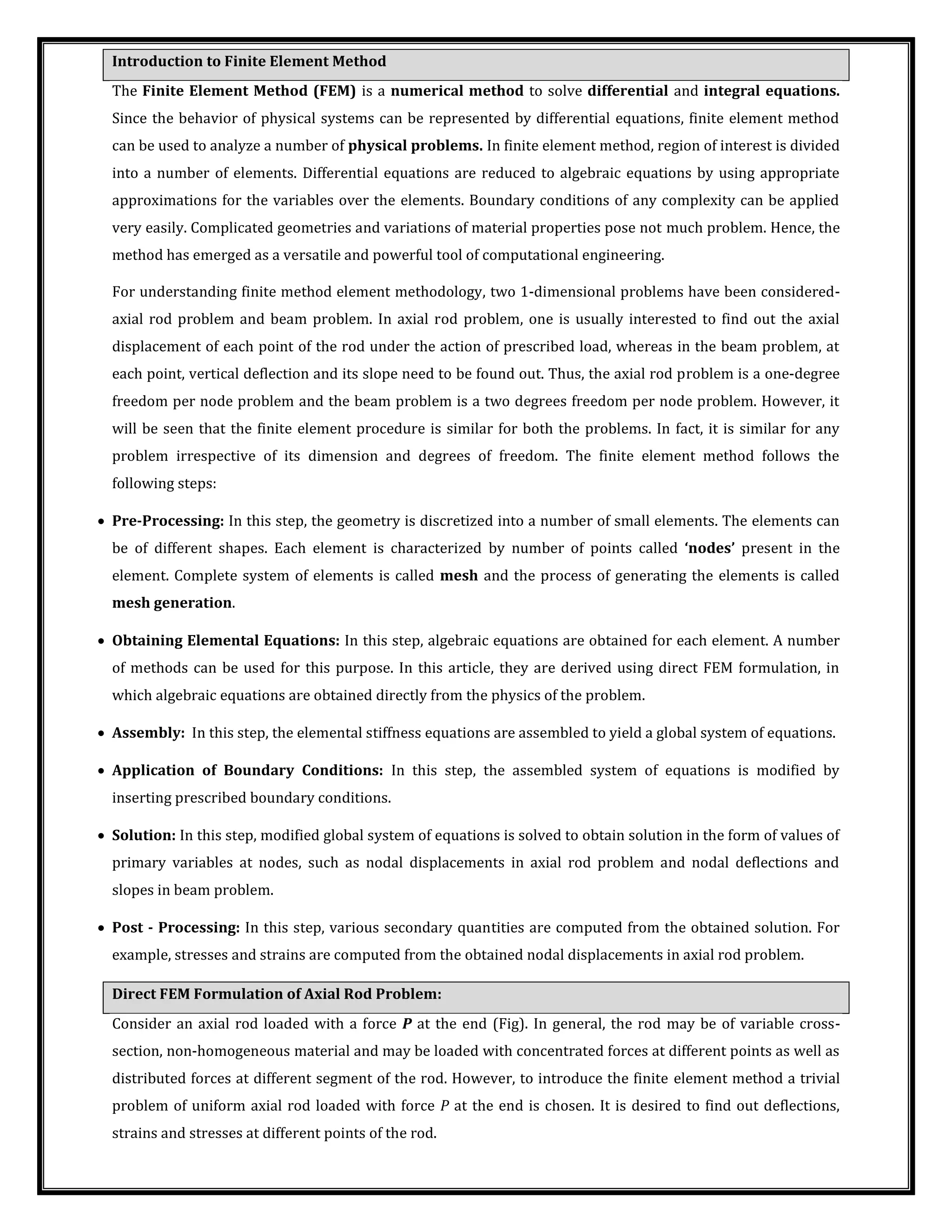
The Finite Element Method (FEM) is a numerical method to solve differential equations by dividing a system into small elements. In FEM, the region of interest is divided into elements and the differential equations are reduced to algebraic equations using approximations over each element. Two example problems, an axial rod problem and a beam problem, are used to introduce the FEM methodology. The methodology involves pre-processing to generate elements, obtaining elemental equations, assembling the equations, applying boundary conditions, solving the system of equations, and post-processing to calculate secondary quantities like stresses and strains.


