Download as PDF, PPTX
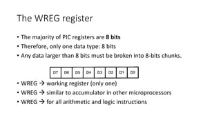
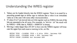
![Program ROM
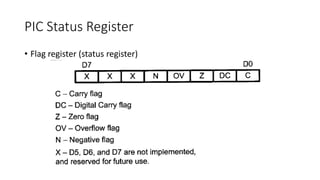
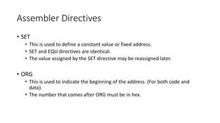
• ROM is used to store programs (program or code ROM)
• PIC 18 program ROM
• Flash [letter F for this]
• OTP (One Time Programmable) [letter C for this]
• Masked (during fabrication process)](https://image.slidesharecdn.com/lecture03basicsofpic-190107151825/85/Lecture-03-basics-of-pic-5-320.jpg)
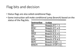
![PIC Status Register
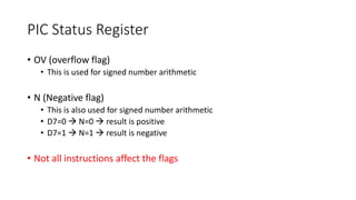
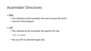
• C (carry flag)
• This is set whenever there is a carry out from D7 bit (8th bit)
• This is affected after 8-bit addition and subtraction
• DC (digital carry flag) [Auxiliary Carry Flag]
• This bit is set whenever if there is a carry from D3 to D4 (during add and sub)
• This is used for BCD arithmetic
• Z (zero flag)
• If the result of arithmetic or logical operation is zero then z=1, otherwise (z=0)
for non-zero result.](https://image.slidesharecdn.com/lecture03basicsofpic-190107151825/85/Lecture-03-basics-of-pic-42-320.jpg)
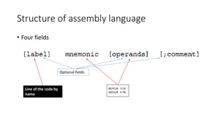
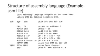
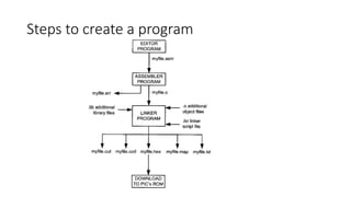
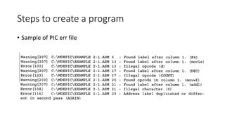


The document provides an overview of the PIC18 microcontroller features, including its RISC architecture, memory types (ROM, RAM, EEPROM), and assembly language programming concepts. It details the use of registers like the WREG and the file register, instruction types, and assembler directives. Additionally, it discusses the program counter and performance enhancement methods for microprocessor design.