Download as PDF, PPTX

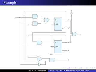
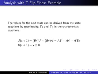
![Example: State equations
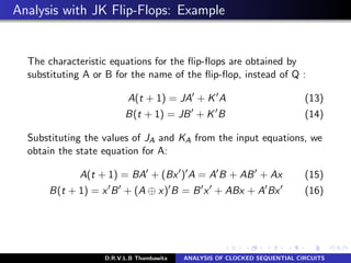
A(t + 1) = A(t)x(t) + B(t)x(t) (1)
B(t + 1) = A (t)x(t) (2)
Boolean expressions are a function of the present state, we can
omit the designation (t) after each variable for convenience and
can express the state equations in the more compact form:
A(t + 1) = Ax + Bx (3)
B(t + 1) = A x (4)
Similarly, the present-state value of the output can be expressed
algebraically as:
y(t) = [A(t) + B(t)]x (t) (5)
By removing the symbol(t)
y = (A + B)x (6)
D.R.V.L.B Thambawita ANALYSIS OF CLOCKED SEQUENTIAL CIRCUITS](https://image.slidesharecdn.com/lec07-181219122811/85/Lec-07-ANALYSIS-OF-CLOCKED-SEQUENTIAL-CIRCUITS-4-320.jpg)
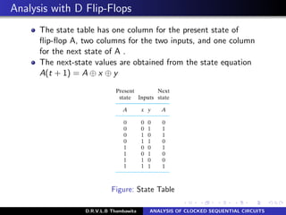
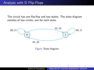
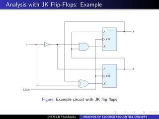
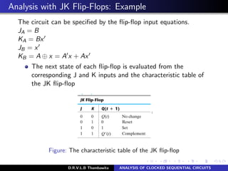
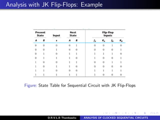
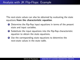
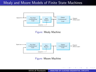
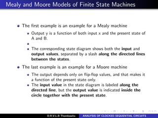
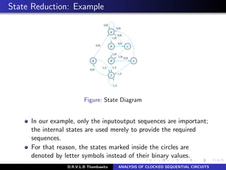

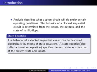
The document analyzes clocked sequential circuits, detailing their behavior through state equations, state tables, and state diagrams. It elucidates the processing of input equations for different types of flip-flops (D, JK, T) and outlines the Mealy and Moore models of finite state machines. Additionally, it discusses state reduction techniques to optimize circuit design by minimizing the number of flip-flops and states while maintaining output functionality.