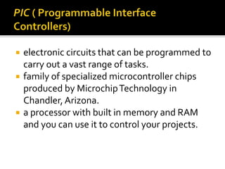
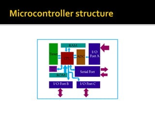
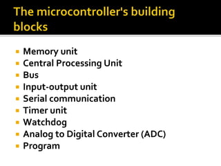
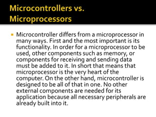
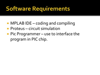
SlideShare a Scribd company logo
 electronic circuits that can be programmed to
carry out a vast range of tasks.
 family of specialized microcontroller chips
produced by MicrochipTechnology in
Chandler,Arizona.
 a processor with built in memory and RAM
and you can use it to control your projects.
 Memory unit
 Central Processing Unit
 Bus
 Input-output unit
 Serial communication
 Timer unit
 Watchdog
 Analog to Digital Converter (ADC)
 Program
 Microcontroller differs from a microprocessor in
many ways. First and the most important is its
functionality. In order for a microprocessor to be
used, other components such as memory, or
components for receiving and sending data
must be added to it. In short that means that
microprocessor is the very heart of the
computer. On the other hand, microcontroller is
designed to be all of that in one. No other
external components are needed for its
application because all necessary peripherals are
already built into it.
 Morse code keyers
 Robots
 Data logging instruments
 Phone dialers
 Clocks and timers
 Much, much more
 The PIC
 PIC16F84A
 A breadboard
 A set of resistors, capacitors and LEDs
 A power supply
 5V DC source
 A PIC Programmer
 MPLAB or another platform
 Contains the arithmetic logic unit
 Bit # 0 – 2
 Reset status of the PIC
 Bit # 3 and 4
 Bank selection bits
 Bit # 5 and 6
 Direct and indirect addressing – bit # 7
 Low level programming language for a
computer or other programmable device
specific to a particular computer architecture
 The PIC family has a very short range of
instructions with just only 35 instructions.
 All instructions have just about the same
format. First comes the name of the
instructions.Then, comes the instructions
fields.The fields may be none, one or two,
according to the instruction.
 The instruction could be filled with file
register (f), a bit address (b), constant data(k),
or destination selection (d).
 General purpose registers in which you can
put any value that you wish.
 The most basic operations that needs to be done will
be the value loading.These operations have to do
with loading a binary, decimal or hexadecimal value
on theW register or to a register.
 Declaring number base in loading a value:
 Binary
▪ b’01010010’
 Decimal
▪ D’35’
 Hexadecimal
▪ 0x1F
▪ 4fh
 movlw k
 Loads literal value k to the W register
 movwf f
 Moves the value from W register to file register f
 movf f,d
 Loads a value from the file register f. If destination
d is equal to 0 the result is stored in the W
register, if d is equal to 1 the result will stored back
to the file register f.
 bsf f , b
 Bit b in the file register f is Set(1).
 bcf f , b
 Bit b in the file register f is Cleared(0).
 btfss f , b
 If the bit 'b' in file register 'f' is 1, then the following instructions is not
executed. If the bit is 0, the instructions is executed normally.
 btfsc f , b
 If the bit 'b' in file register 'f' is 0, then the following instructions is not
executed. If the bit is 1, the instructions is executed normally.
 swapf f , d
 The upper and lower nibbles of file register 'f' are exchanged. If d is 0
the result is stored in theW register, if d is 1 the result is stored back to
the file register 'f'.
 GOTO k
 Send program flow directly to a program line or label.
 CALL k
 Send program flow directly to a program line or label. A RETURN instruction
will send the program flow back to the position where the CALL was made.
 RETURN
 This instruction will send the program flow to the last position, usually, this is
done by a previous CALL instruction
 RETLW k
 This instruction will send the program flow to the last position, usually, this is
done by a previous CALL instruction.Also, the W register will get the value k
on return.
 RETFIE
 This is a RETurn From Interrupt instruction.This instruction will send the
program flow back to the position where the last interrupt occurred and
caused the program flow to go to the interrupt vector (0x04h).
 RLF f , d
 Rotate Left through carry.The bits are rotated one position left
through the Carry. If d is 0 the result is stored in the W register, if d is 1
the result is stored back to the file register 'f'.
 RRF f , d
 Rotate Right through carry.The bits are rotated one position right
through the Carry. If d is 0 the result is stored in the W register, if d is 1
the result is stored back to the file register 'f'.
 INCF f , d
 The contents of register 'f' are increased by 1. If d is 0 the result is
stored in theW register, if d is 1 the result is stored back to the file
register 'f'.
 DECF f , d
 The contents of register 'f' are decreased by 1. If d is 0 the result is
stored in theW register, if d is 1 the result is stored back to the file
register 'f'.
 INCFSZ f , d
 The contents of register 'f' are increased by 1. If d is 0 the result
is stored in the W register, if d is 1 the result is stored back to the
file register 'f'. If the result is '0', the very next instruction is not
executed.
 DECFSZ f , d
 The contents of register 'f' are decreased by 1. If d is 0 the result
is stored in the W register, if d is 1 the result is stored back to the
file register 'f'. If the result is '0', the very next instruction and is
not executed.
 CLRF f
 The register 'f' is cleared.
 CLRW
 The working register W is cleared.
 ADDLW k
 Add the content of W register with a literal value and store the result in theW
register
 ADDWF f , d
 Add the content of W register with the content of a file register 'f'. If d is 0 the
result is stored in the W register, if d is 1 the result is stored back to the file
register 'f'.
 SUBLW k
 Subtract the content ofW register from a literal value and store the result in
theW register.
 SUBWF f , d
 Subtract the content ofW register from the content of a file register 'f'. If d is 0
the result is stored in theW register, if d is 1 the result is stored back to the file
register 'f'.
 COMF f , d
 The contents of the file register 'f' are complemented. If d is 0 the result is
stored in theW register, if d is 1 the result is stored back to the file register 'f'.
 ANDLW k
 Logic AND between the contents ofW and the literal value k.
The results is stored back to W.
 ANDWF f , d
 Logic AND between the content ofW register with the content
of a file register 'f'. If d is 0 the result is stored in theW register, if
d is 1 the result is stored back to the file register 'f'.
 IORLW k
 Logic OR between the contents ofW and the literal value k.The
results is stored back toW.
 IORWF f , d
 Logic OR between the content ofW register from the content of
a file register 'f'. If d is 0 the result is stored in the W register, if d
is 1 the result is stored back to the file register 'f'.
 XORLW k
 Logic EXCLUSIVE OR between the contents ofW
and the literal value k.The results is stored back to
W.
 XORWF f , d
 Logic EXCLUSIVE OR between the content ofW
register from the content of a file register 'f'. If d is
0 the result is stored in theW register, if d is 1 the
result is stored back to the file register 'f'.
 NOP
 This instructions is the No Operations instructions
and does nothing at all.
 CLRWDT
 This instructions will reset theWatchdogTimer
 SLEEP
 This instructions will put the chip into Sleep mode
 All these instructions set the Z flag of the
status register if their result is zero.
Otherwise, the Z flag is cleared.
Result Carry Zero
Positiv
e
1 0
Zero 1 1
Negati
ve
0 0
 MPLAB IDE – coding and compiling
 Proteus – circuit simulation
 Pic Programmer – use to interface the
program in PIC chip.

More Related Content

Similar to PIC Microcontroller Structure & Assembly Language.ppsx

EMBEDDED SYSTEMS 4&5
EMBEDDED SYSTEMS 4&5EMBEDDED SYSTEMS 4&5
EMBEDDED SYSTEMS 4&5
PRADEEP
 
Chp6 assembly language programming for pic copy
Chp6 assembly language programming for pic   copyChp6 assembly language programming for pic   copy
Chp6 assembly language programming for pic copy
mkazree
 
Chap 3_2.ppt
Chap 3_2.pptChap 3_2.ppt
Chap 3_2.ppt
inian2
 

Similar to PIC Microcontroller Structure & Assembly Language.ppsx (20)

EMBEDDED SYSTEMS 4&5
EMBEDDED SYSTEMS 4&5EMBEDDED SYSTEMS 4&5
EMBEDDED SYSTEMS 4&5
 
Instruction set of 8086 Microprocessor
Instruction set of 8086 Microprocessor Instruction set of 8086 Microprocessor
Instruction set of 8086 Microprocessor
 
Instruction_Set.pdf
Instruction_Set.pdfInstruction_Set.pdf
Instruction_Set.pdf
 
Instruction Level Parallelism – Compiler Techniques
Instruction Level Parallelism – Compiler TechniquesInstruction Level Parallelism – Compiler Techniques
Instruction Level Parallelism – Compiler Techniques
 
8085 paper-presentation
8085 paper-presentation8085 paper-presentation
8085 paper-presentation
 
Instruction set
Instruction setInstruction set
Instruction set
 
Stack and subroutine
Stack and subroutineStack and subroutine
Stack and subroutine
 
Stacks & subroutines 1
Stacks & subroutines 1Stacks & subroutines 1
Stacks & subroutines 1
 
Real Time Embedded System
Real Time Embedded SystemReal Time Embedded System
Real Time Embedded System
 
Consistent Updates in Software-De!ned Networks
Consistent Updates in Software-De!ned NetworksConsistent Updates in Software-De!ned Networks
Consistent Updates in Software-De!ned Networks
 
DPDK & Layer 4 Packet Processing
DPDK & Layer 4 Packet ProcessingDPDK & Layer 4 Packet Processing
DPDK & Layer 4 Packet Processing
 
Chp6 assembly language programming for pic copy
Chp6 assembly language programming for pic   copyChp6 assembly language programming for pic   copy
Chp6 assembly language programming for pic copy
 
eBPF Tooling and Debugging Infrastructure
eBPF Tooling and Debugging InfrastructureeBPF Tooling and Debugging Infrastructure
eBPF Tooling and Debugging Infrastructure
 
ARM procedure calling conventions and recursion
ARM procedure calling conventions and recursionARM procedure calling conventions and recursion
ARM procedure calling conventions and recursion
 
module2.ppt
module2.pptmodule2.ppt
module2.ppt
 
Low-level Shader Optimization for Next-Gen and DX11 by Emil Persson
Low-level Shader Optimization for Next-Gen and DX11 by Emil PerssonLow-level Shader Optimization for Next-Gen and DX11 by Emil Persson
Low-level Shader Optimization for Next-Gen and DX11 by Emil Persson
 
5G Network Slicing Using Mininet
5G Network Slicing Using Mininet5G Network Slicing Using Mininet
5G Network Slicing Using Mininet
 
Ch2 microcontroller architecture
Ch2 microcontroller architectureCh2 microcontroller architecture
Ch2 microcontroller architecture
 
Chap 3_2.ppt
Chap 3_2.pptChap 3_2.ppt
Chap 3_2.ppt
 
Microprocessor Microcontroller Interview & Viva Question.pdf
Microprocessor Microcontroller Interview & Viva Question.pdfMicroprocessor Microcontroller Interview & Viva Question.pdf
Microprocessor Microcontroller Interview & Viva Question.pdf
 

Recently uploaded

Production 2024 sunderland culture final - Copy.pptx
Production 2024 sunderland culture final - Copy.pptxProduction 2024 sunderland culture final - Copy.pptx
Production 2024 sunderland culture final - Copy.pptx
ChloeMeadows1
 
audience research (emma) 1.pptxkkkkkkkkkkkkkkkkk
audience research (emma) 1.pptxkkkkkkkkkkkkkkkkkaudience research (emma) 1.pptxkkkkkkkkkkkkkkkkk
audience research (emma) 1.pptxkkkkkkkkkkkkkkkkk
lolsDocherty
 
Article writing on excessive use of internet.pptx
Article writing on excessive use of internet.pptxArticle writing on excessive use of internet.pptx
Article writing on excessive use of internet.pptx
abhinandnam9997
 
一比一原版UTS毕业证悉尼科技大学毕业证成绩单如何办理
一比一原版UTS毕业证悉尼科技大学毕业证成绩单如何办理一比一原版UTS毕业证悉尼科技大学毕业证成绩单如何办理
一比一原版UTS毕业证悉尼科技大学毕业证成绩单如何办理
aagad
 

Recently uploaded (14)

Production 2024 sunderland culture final - Copy.pptx
Production 2024 sunderland culture final - Copy.pptxProduction 2024 sunderland culture final - Copy.pptx
Production 2024 sunderland culture final - Copy.pptx
 
The Use of AI in Indonesia Election 2024: A Case Study
The Use of AI in Indonesia Election 2024: A Case StudyThe Use of AI in Indonesia Election 2024: A Case Study
The Use of AI in Indonesia Election 2024: A Case Study
 
Bug Bounty Blueprint : A Beginner's Guide
Bug Bounty Blueprint : A Beginner's GuideBug Bounty Blueprint : A Beginner's Guide
Bug Bounty Blueprint : A Beginner's Guide
 
audience research (emma) 1.pptxkkkkkkkkkkkkkkkkk
audience research (emma) 1.pptxkkkkkkkkkkkkkkkkkaudience research (emma) 1.pptxkkkkkkkkkkkkkkkkk
audience research (emma) 1.pptxkkkkkkkkkkkkkkkkk
 
ER(Entity Relationship) Diagram for online shopping - TAE
ER(Entity Relationship) Diagram for online shopping - TAEER(Entity Relationship) Diagram for online shopping - TAE
ER(Entity Relationship) Diagram for online shopping - TAE
 
Article writing on excessive use of internet.pptx
Article writing on excessive use of internet.pptxArticle writing on excessive use of internet.pptx
Article writing on excessive use of internet.pptx
 
Multi-cluster Kubernetes Networking- Patterns, Projects and Guidelines
Multi-cluster Kubernetes Networking- Patterns, Projects and GuidelinesMulti-cluster Kubernetes Networking- Patterns, Projects and Guidelines
Multi-cluster Kubernetes Networking- Patterns, Projects and Guidelines
 
Statistical Analysis of DNS Latencies.pdf
Statistical Analysis of DNS Latencies.pdfStatistical Analysis of DNS Latencies.pdf
Statistical Analysis of DNS Latencies.pdf
 
How Do I Begin the Linksys Velop Setup Process?
How Do I Begin the Linksys Velop Setup Process?How Do I Begin the Linksys Velop Setup Process?
How Do I Begin the Linksys Velop Setup Process?
 
Premier Mobile App Development Agency in USA.pdf
Premier Mobile App Development Agency in USA.pdfPremier Mobile App Development Agency in USA.pdf
Premier Mobile App Development Agency in USA.pdf
 
Cyber Security Services Unveiled: Strategies to Secure Your Digital Presence
Cyber Security Services Unveiled: Strategies to Secure Your Digital PresenceCyber Security Services Unveiled: Strategies to Secure Your Digital Presence
Cyber Security Services Unveiled: Strategies to Secure Your Digital Presence
 
一比一原版UTS毕业证悉尼科技大学毕业证成绩单如何办理
一比一原版UTS毕业证悉尼科技大学毕业证成绩单如何办理一比一原版UTS毕业证悉尼科技大学毕业证成绩单如何办理
一比一原版UTS毕业证悉尼科技大学毕业证成绩单如何办理
 
Case study on merger of Vodafone and Idea (VI).pptx
Case study on merger of Vodafone and Idea (VI).pptxCase study on merger of Vodafone and Idea (VI).pptx
Case study on merger of Vodafone and Idea (VI).pptx
 
Pvtaan Social media marketing proposal.pdf
Pvtaan Social media marketing proposal.pdfPvtaan Social media marketing proposal.pdf
Pvtaan Social media marketing proposal.pdf
 

PIC Microcontroller Structure & Assembly Language.ppsx

  • 1.
  • 2.  electronic circuits that can be programmed to carry out a vast range of tasks.  family of specialized microcontroller chips produced by MicrochipTechnology in Chandler,Arizona.  a processor with built in memory and RAM and you can use it to control your projects.
  • 3.
  • 4.  Memory unit  Central Processing Unit  Bus  Input-output unit  Serial communication  Timer unit  Watchdog  Analog to Digital Converter (ADC)  Program
  • 5.  Microcontroller differs from a microprocessor in many ways. First and the most important is its functionality. In order for a microprocessor to be used, other components such as memory, or components for receiving and sending data must be added to it. In short that means that microprocessor is the very heart of the computer. On the other hand, microcontroller is designed to be all of that in one. No other external components are needed for its application because all necessary peripherals are already built into it.
  • 6.  Morse code keyers  Robots  Data logging instruments  Phone dialers  Clocks and timers  Much, much more
  • 7.  The PIC  PIC16F84A  A breadboard  A set of resistors, capacitors and LEDs  A power supply  5V DC source  A PIC Programmer  MPLAB or another platform
  • 8.
  • 9.
  • 10.  Contains the arithmetic logic unit  Bit # 0 – 2  Reset status of the PIC  Bit # 3 and 4  Bank selection bits  Bit # 5 and 6  Direct and indirect addressing – bit # 7
  • 11.  Low level programming language for a computer or other programmable device specific to a particular computer architecture
  • 12.
  • 13.  The PIC family has a very short range of instructions with just only 35 instructions.  All instructions have just about the same format. First comes the name of the instructions.Then, comes the instructions fields.The fields may be none, one or two, according to the instruction.  The instruction could be filled with file register (f), a bit address (b), constant data(k), or destination selection (d).
  • 14.  General purpose registers in which you can put any value that you wish.
  • 15.  The most basic operations that needs to be done will be the value loading.These operations have to do with loading a binary, decimal or hexadecimal value on theW register or to a register.  Declaring number base in loading a value:  Binary ▪ b’01010010’  Decimal ▪ D’35’  Hexadecimal ▪ 0x1F ▪ 4fh
  • 16.  movlw k  Loads literal value k to the W register  movwf f  Moves the value from W register to file register f  movf f,d  Loads a value from the file register f. If destination d is equal to 0 the result is stored in the W register, if d is equal to 1 the result will stored back to the file register f.
  • 17.  bsf f , b  Bit b in the file register f is Set(1).  bcf f , b  Bit b in the file register f is Cleared(0).  btfss f , b  If the bit 'b' in file register 'f' is 1, then the following instructions is not executed. If the bit is 0, the instructions is executed normally.  btfsc f , b  If the bit 'b' in file register 'f' is 0, then the following instructions is not executed. If the bit is 1, the instructions is executed normally.  swapf f , d  The upper and lower nibbles of file register 'f' are exchanged. If d is 0 the result is stored in theW register, if d is 1 the result is stored back to the file register 'f'.
  • 18.  GOTO k  Send program flow directly to a program line or label.  CALL k  Send program flow directly to a program line or label. A RETURN instruction will send the program flow back to the position where the CALL was made.  RETURN  This instruction will send the program flow to the last position, usually, this is done by a previous CALL instruction  RETLW k  This instruction will send the program flow to the last position, usually, this is done by a previous CALL instruction.Also, the W register will get the value k on return.  RETFIE  This is a RETurn From Interrupt instruction.This instruction will send the program flow back to the position where the last interrupt occurred and caused the program flow to go to the interrupt vector (0x04h).
  • 19.  RLF f , d  Rotate Left through carry.The bits are rotated one position left through the Carry. If d is 0 the result is stored in the W register, if d is 1 the result is stored back to the file register 'f'.  RRF f , d  Rotate Right through carry.The bits are rotated one position right through the Carry. If d is 0 the result is stored in the W register, if d is 1 the result is stored back to the file register 'f'.  INCF f , d  The contents of register 'f' are increased by 1. If d is 0 the result is stored in theW register, if d is 1 the result is stored back to the file register 'f'.  DECF f , d  The contents of register 'f' are decreased by 1. If d is 0 the result is stored in theW register, if d is 1 the result is stored back to the file register 'f'.
  • 20.  INCFSZ f , d  The contents of register 'f' are increased by 1. If d is 0 the result is stored in the W register, if d is 1 the result is stored back to the file register 'f'. If the result is '0', the very next instruction is not executed.  DECFSZ f , d  The contents of register 'f' are decreased by 1. If d is 0 the result is stored in the W register, if d is 1 the result is stored back to the file register 'f'. If the result is '0', the very next instruction and is not executed.  CLRF f  The register 'f' is cleared.  CLRW  The working register W is cleared.
  • 21.  ADDLW k  Add the content of W register with a literal value and store the result in theW register  ADDWF f , d  Add the content of W register with the content of a file register 'f'. If d is 0 the result is stored in the W register, if d is 1 the result is stored back to the file register 'f'.  SUBLW k  Subtract the content ofW register from a literal value and store the result in theW register.  SUBWF f , d  Subtract the content ofW register from the content of a file register 'f'. If d is 0 the result is stored in theW register, if d is 1 the result is stored back to the file register 'f'.  COMF f , d  The contents of the file register 'f' are complemented. If d is 0 the result is stored in theW register, if d is 1 the result is stored back to the file register 'f'.
  • 22.  ANDLW k  Logic AND between the contents ofW and the literal value k. The results is stored back to W.  ANDWF f , d  Logic AND between the content ofW register with the content of a file register 'f'. If d is 0 the result is stored in theW register, if d is 1 the result is stored back to the file register 'f'.  IORLW k  Logic OR between the contents ofW and the literal value k.The results is stored back toW.  IORWF f , d  Logic OR between the content ofW register from the content of a file register 'f'. If d is 0 the result is stored in the W register, if d is 1 the result is stored back to the file register 'f'.
  • 23.  XORLW k  Logic EXCLUSIVE OR between the contents ofW and the literal value k.The results is stored back to W.  XORWF f , d  Logic EXCLUSIVE OR between the content ofW register from the content of a file register 'f'. If d is 0 the result is stored in theW register, if d is 1 the result is stored back to the file register 'f'.
  • 24.  NOP  This instructions is the No Operations instructions and does nothing at all.  CLRWDT  This instructions will reset theWatchdogTimer  SLEEP  This instructions will put the chip into Sleep mode
  • 25.  All these instructions set the Z flag of the status register if their result is zero. Otherwise, the Z flag is cleared.
  • 26. Result Carry Zero Positiv e 1 0 Zero 1 1 Negati ve 0 0
  • 27.  MPLAB IDE – coding and compiling  Proteus – circuit simulation  Pic Programmer – use to interface the program in PIC chip.