Download as PDF, PPTX


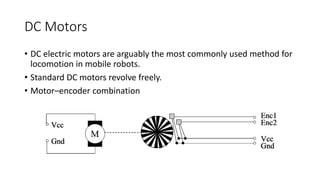
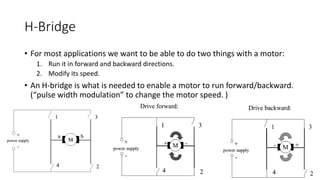
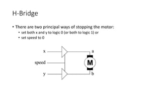
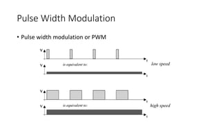
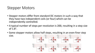
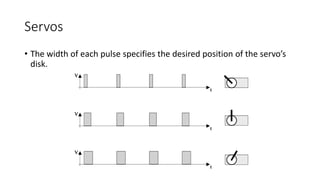


Sensors and actuators are important components for robots. Sensors can be analog or digital and include sensors for position, orientation, distance, light, and more. The right sensor must match the application needs. Actuators allow robots to move and interact with their environment. Common actuators include DC motors, stepper motors, and servos, which can be controlled through techniques like pulse-width modulation. Together, sensors and actuators enable robots to perceive and interact with the world.