Microcontroller Based System Design Unit-II PIC Interrupts.pptx
1.
KONGUNADU COLLEGE OFENGINEERING &
TECHNOLOGY
(AUTONOMOUS)
20EE807PE – MICROCONTROLLER BASED SYSTEM
DESIGN
UNIT – II
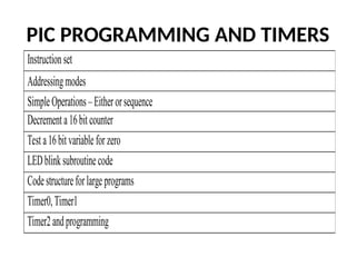
PIC PROGRAMMING AND TIMERS
TAMILNESAN P,
AP/EEE
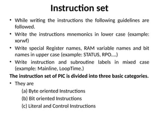
Instruction set
• Whilewriting the instructions the following guidelines are
followed.
• Write the instructions mnemonics in lower case (example:
xorwf)
• Write special Register names, RAM variable names and bit
names in upper case (example: STATUS, RPO….)
• Write instruction and subroutine labels in mixed case
(example: Mainline, LoopTime.)
The instruction set of PIC is divided into three basic categories.
• They are
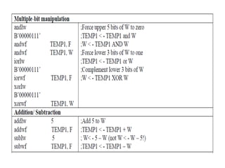
(a) Byte oriented Instructions
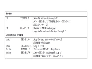
(b) Bit oriented Instructions
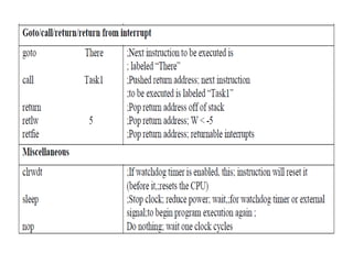
(c) Literal and Control Instructions
4.
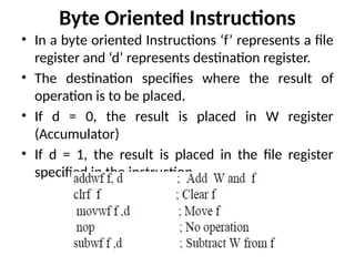
Byte Oriented Instructions
•In a byte oriented Instructions ‘f’ represents a file
register and ‘d’ represents destination register.
• The destination specifies where the result of
operation is to be placed.
• If d = 0, the result is placed in W register
(Accumulator)
• If d = 1, the result is placed in the file register
specified in the instruction.
5.
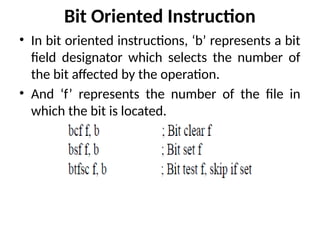
Bit Oriented Instruction
•In bit oriented instructions, ‘b’ represents a bit
field designator which selects the number of
the bit affected by the operation.
• And ‘f’ represents the number of the file in
which the bit is located.
6.
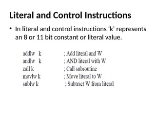
Literal and ControlInstructions
• In literal and control instructions ‘k’ represents
an 8 or 11 bit constant or literal value.
7.
CLASSIFICATION OF INSTRUCTIONS:[Based
on Operation]
• All the instructions of the PIC microcontroller are classified into
nearly 9 groups. They are given below with examples.
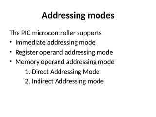
Immediate addressing mode:
•In this mode, the operand is a number or
constant, not an address as MOVLW43H.
• The operand here is a data not an address.
• So in this addressing mode of PIC
microcontroller data is direct transfer and data
is immediately after opcode.
13.
Register operand addressingmode
• In this mode the operand is a register which
holds the data to be execute.
• Register operand addressing mode deals with
registers like W, FSR (File Select Register), INDT
(Indirect Register)
14.
Memory Operand addressingmode
• In this mode, the operand is an address of
memory location which holds the data to be
execute.
• The memory operand addressing mode is
classified into,
Direct addressing mode
Indirect addressing mode
15.
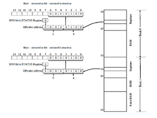
Direct Addressing Mode
•In direct addressing mode 7 bits (0-6) of the
instruction identify the register file address and the
8th bit of the register file address register bank select
bit (RP0).
• The figure illustrates direct addressing being used to
access register file address 14H or 94H depending on
the value of RP0.
• If the RP0 bit in STATUS register is 0, then the effective
address feeds the 14H in to the Register in the Bank 0.
• If the RP0 bit is 1, then the effective address feeds the
94H in to the register in the Bank 1.
17.
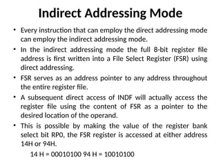
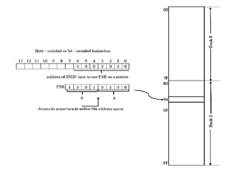
Indirect Addressing Mode
•Every instruction that can employ the direct addressing mode
can employ the indirect addressing mode.
• In the indirect addressing mode the full 8-bit register file
address is first written into a File Select Register (FSR) using
direct addressing.
• FSR serves as an address pointer to any address throughout
the entire register file.
• A subsequent direct access of INDF will actually access the
register file using the content of FSR as a pointer to the
desired location of the operand.
• This is possible by making the value of the register bank
select bit RP0, the FSR register is accessed at either address
14H or 94H.
14 H = 00010100 94 H = 10010100

![CLASSIFICATION OF INSTRUCTIONS: [Based
on Operation]
• All the instructions of the PIC microcontroller are classified into
nearly 9 groups. They are given below with examples.](https://image.slidesharecdn.com/unit-ii-251218100105-2c53ec54/85/Microcontroller-Based-System-Design-Unit-II-PIC-Interrupts-pptx-7-320.jpg)