Download to read offline

![١/١٢/١٤٣٦
٢
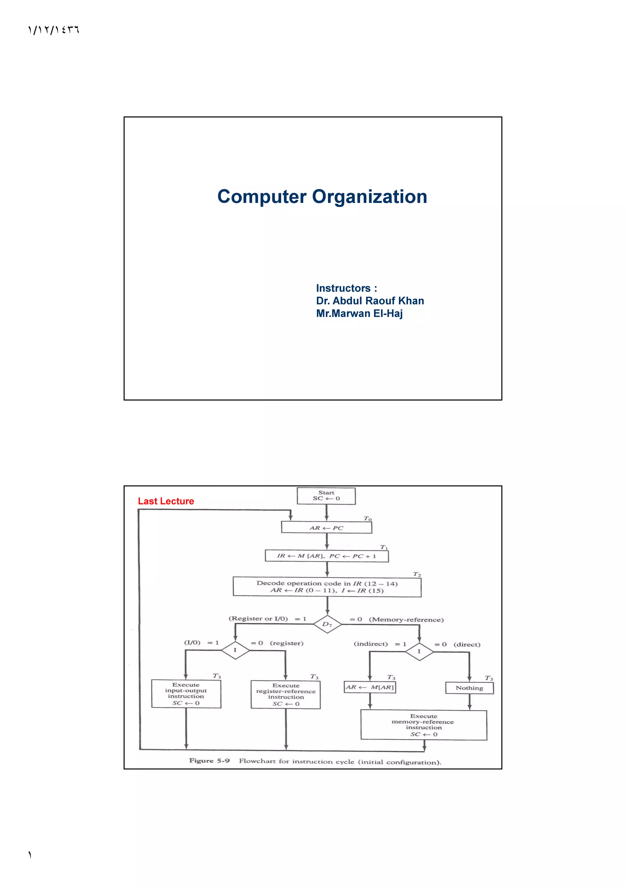
Determine the type of Instruction
The three instruction types are subdivided
into four separate paths
D’7IT3 : AR M[AR]
D’7I’T3 : Nothing
D7I’T3 : Execute register-reference Instruction
D7IT3 : Execute Input-Output instruction
Last Lecture
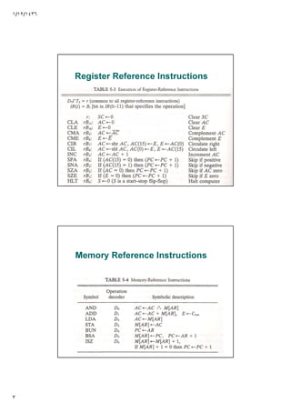
Register Reference Instructions
The control function and Microoperation for
register reference are listed below. These
instructions are executed with the clock
transition associated with timing Variable T3.
Each control function needs the Boolean
relation D7I’ T3, which we designate by r.
The control function is distinguished by one
of the bits in IR(0-11)](https://image.slidesharecdn.com/molexqjhqtgvpy0zutcz-signature-0a4922234e76dd63e069a6bd18dc04eb91d65155d5eb6817e3dd5da56ee52bda-poli-170322104337/85/Lect9-organization-2-320.jpg)
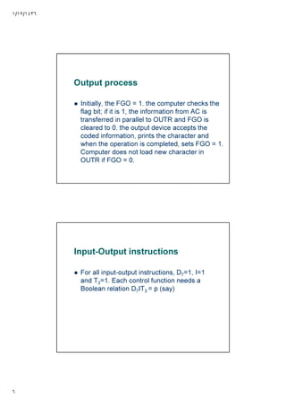
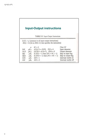

This document discusses different types of computer instructions including register reference instructions, memory reference instructions, and input-output instructions. It describes the control functions and microoperations for register reference instructions which are executed when D7I'T3 is true. Memory reference instructions and an example of the BSA instruction are also mentioned. The input and output processes are defined, noting how input and output flags control the transfer of data between registers and input/output devices. Finally, it states that all input-output instructions have D7=1, I=1, and T3=1 and require the Boolean relation D7IT3 to be true.