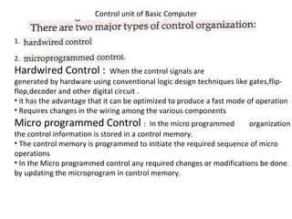
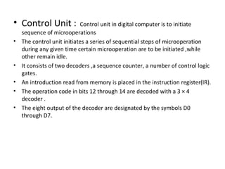
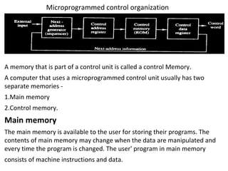
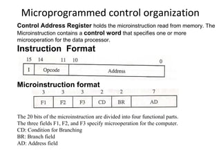
Control unit of Basic Computer 
1. 
2. 
Hardwired Control : When the control signals are 
generated by hardware using conventional logic design techniques like gates,flip-flop, 
decoder and other digital circuit . 
• it has the advantage that it can be optimized to produce a fast mode of operation 
• Requires changes in the wiring among the various components 
Micro programmed Control : In the micro programmed organization 
the control information is stored in a control memory. 
• The control memory is programmed to initiate the required sequence of micro 
operations 
• In the Micro programmed control any required changes or modifications be done 
by updating the microprogram in control memory.
• Control Unit : Control unit in digital computer is to initiate 
sequence of microoperations 
• The control unit initiates a series of sequential steps of microoperation 
during any given time certain microoperation are to be initiated ,while 
other remain idle. 
• It consists of two decoders ,a sequence counter, a number of control logic 
gates. 
• An introduction read from memory is placed in the instruction register(IR). 
• The operation code in bits 12 through 14 are decoded with a 3 × 4 
decoder . 
• The eight output of the decoder are designated by the symbols D0 
through D7.
B 
L 
O 
C 
K 
D 
I 
A 
G 
R 
A 
M 
O 
F 
CU
Microprogrammed control organization 
A memory that is part of a control unit is called a control Memory. 
A computer that uses a microprogrammed control unit usually has two 
separate memories - 
1.Main memory 
2.Control memory. 
Main memory 
The main memory is available to the user for storing their programs. The 
contents of main memory may change when the data are manipulated and 
every time the program is changed. The user' program in main memory 
consists of machine instructions and data.
Microprogrammed control organization 
control memory holds a fixed microprogram that cannot be 
altered by the occasional user. usually a ROM, which stores all control 
information permanently 
Microprogram Sequencer 
A microprogram sequencer is the next address generator, as it determines the 
address sequence that is read from control memory. The address of the next 
microinstruction can be specified in several ways depending on the sequencer 
inputs. The functions of a microprogram sequencer are incrementing the control 
address register by one 
Control data register (DR) 
The control DR(data register) stores the present microinstruction while the next 
address is computed and read from memory. The data register is also called a 
pipeline register. It allows the execution of the microoperations specified by the 
control word simultaneously with the generation of the next microinstruction
Microprogrammed control organization 
Control Address Register holds the microinstruction read from memory. The 
Microinstruction contains a control word that specifies one or more 
microoperation for the data processor. 
Instruction Format 
Microinstruction format 
The 20 bits of the microinstruction are divided into four functional parts. 
The three fields F1, F2, and F3 specify microoperation for the computer. 
CD: Condition for Branching 
BR: Branch field 
AD: Address field
Selection of Address for control Memory
Addition and Subtraction 
We consider addition,subtraction,multiplication,and division 
for the following types of data: 
• Fixed-Point binary data in signed-magnitude 
representation 
• Fixed-Point binary data in signed-2’s compliment 
representation 
• Floating point binary data
Addition and Subtraction 
A processor has an arithmetic processor(as a sub part of 
it) that executes arithmetic operations. The data 
type, assumed to reside in processor, registers during 
the execution of an arithmetic instruction. Negative 
numbers may be in a signed magnitude or signed 
complement representation. 
There are three ways of representing negative fixed point 
- binary numbers 
1.signed magnitude, 
2. signed 1’s complement 
2. Signed 2’s complement. 
Most computers use the signed magnitude epresentation 
for the mantissa
Addition and Subtraction With Signed-Magnitude Data 
Addition and Subtraction With Signed-Magnitude Numbers
hardware implementation for signed magnitude 
addition and subtraction 
As and Bs is a sign flip-flop 
Output carry is transferred to flip-flop E 
AVF holdes the overflow bit
hardware implementation for signed magnitude 
addition and subtraction 
As and Bs is a sign flip-flop 
Output carry is transferred to flip-flop E 
AVF holdes the overflow bit
Flowchart for add and subtract operation
Addition and Subtraction With Signed-2’s Compliment 
Data
Addition and Subtraction With Signed-2’s 
Compliment Data 
• The leftmost bit of a binary number represents the sign : 0 to 
denote positive and 1 to denote negative. 
• If the sign bit is 1, then we represent number in 2's 
complement form. 
• Thus + 33 is represented as 00100000 and -33 as 
11011110. Note that 11011110 is the 2's complement of 
00100000 
• The addition of two numbers in signed 2's complement form 
by adding the numbers with the sign bits treated the same 
as the other bits of the number. We discard the carry of the 
sign-bit position. 
• The subtraction consists of first taking the 2's complement 
of the subtrahend and then adding it to the minuend.
• We can detect an overflow by inspecting the last 
two carries of the addition. When the two carries 
are applied to an exclusive-OR gate, the verflow 
is detected when the output of the gate is equal 
to 1.
Multiplication Algorithm 
Multiplication of two fixed-point binary numbers in signed magnitude representation
Hardware for Multiply operation
Multiplication Algorithm 
• The multiplier is stored in the register 
• and its sign in Qs. 
• The sequence counter SC is initially set bits in 
the multiplier. After forming each partial 
product the counter is decremented. When 
the content of the counter reaches zero, the 
product is complete and we stop the process.
Booth multiplication algorithm 
Booth algorithm needs examination of the multiplier bits and shifting of the 
partial product. Prior to the shifting, the multiplicand added to the partial 
product, subtracted from the partial product, or left unchanged by the 
following rules: 
1. The multiplicand is subtracted from the partial product when we get the first 
least significant 1 in a string of 1' in the multiplier. 
2. The multiplicand is added to the partial product when we get the first Q 
(provided that there was a previous 1) in a string of 0' in the multiplier. 
3. The partial product does not change when the multiplier bit is the same as 
the previous multiplier bit.
control unit
control unit
control unit
control unit

control unit

  • 2.
    Control unit ofBasic Computer 1. 2. Hardwired Control : When the control signals are generated by hardware using conventional logic design techniques like gates,flip-flop, decoder and other digital circuit . • it has the advantage that it can be optimized to produce a fast mode of operation • Requires changes in the wiring among the various components Micro programmed Control : In the micro programmed organization the control information is stored in a control memory. • The control memory is programmed to initiate the required sequence of micro operations • In the Micro programmed control any required changes or modifications be done by updating the microprogram in control memory.
  • 3.
    • Control Unit: Control unit in digital computer is to initiate sequence of microoperations • The control unit initiates a series of sequential steps of microoperation during any given time certain microoperation are to be initiated ,while other remain idle. • It consists of two decoders ,a sequence counter, a number of control logic gates. • An introduction read from memory is placed in the instruction register(IR). • The operation code in bits 12 through 14 are decoded with a 3 × 4 decoder . • The eight output of the decoder are designated by the symbols D0 through D7.
  • 4.
    B L O C K D I A G R A M O F CU
  • 5.
    Microprogrammed control organization A memory that is part of a control unit is called a control Memory. A computer that uses a microprogrammed control unit usually has two separate memories - 1.Main memory 2.Control memory. Main memory The main memory is available to the user for storing their programs. The contents of main memory may change when the data are manipulated and every time the program is changed. The user' program in main memory consists of machine instructions and data.
  • 6.
    Microprogrammed control organization control memory holds a fixed microprogram that cannot be altered by the occasional user. usually a ROM, which stores all control information permanently Microprogram Sequencer A microprogram sequencer is the next address generator, as it determines the address sequence that is read from control memory. The address of the next microinstruction can be specified in several ways depending on the sequencer inputs. The functions of a microprogram sequencer are incrementing the control address register by one Control data register (DR) The control DR(data register) stores the present microinstruction while the next address is computed and read from memory. The data register is also called a pipeline register. It allows the execution of the microoperations specified by the control word simultaneously with the generation of the next microinstruction
  • 7.
    Microprogrammed control organization Control Address Register holds the microinstruction read from memory. The Microinstruction contains a control word that specifies one or more microoperation for the data processor. Instruction Format Microinstruction format The 20 bits of the microinstruction are divided into four functional parts. The three fields F1, F2, and F3 specify microoperation for the computer. CD: Condition for Branching BR: Branch field AD: Address field
  • 13.
    Selection of Addressfor control Memory
  • 18.
    Addition and Subtraction We consider addition,subtraction,multiplication,and division for the following types of data: • Fixed-Point binary data in signed-magnitude representation • Fixed-Point binary data in signed-2’s compliment representation • Floating point binary data
  • 19.
    Addition and Subtraction A processor has an arithmetic processor(as a sub part of it) that executes arithmetic operations. The data type, assumed to reside in processor, registers during the execution of an arithmetic instruction. Negative numbers may be in a signed magnitude or signed complement representation. There are three ways of representing negative fixed point - binary numbers 1.signed magnitude, 2. signed 1’s complement 2. Signed 2’s complement. Most computers use the signed magnitude epresentation for the mantissa
  • 20.
    Addition and SubtractionWith Signed-Magnitude Data Addition and Subtraction With Signed-Magnitude Numbers
  • 25.
    hardware implementation forsigned magnitude addition and subtraction As and Bs is a sign flip-flop Output carry is transferred to flip-flop E AVF holdes the overflow bit
  • 26.
    hardware implementation forsigned magnitude addition and subtraction As and Bs is a sign flip-flop Output carry is transferred to flip-flop E AVF holdes the overflow bit
  • 27.
    Flowchart for addand subtract operation
  • 28.
    Addition and SubtractionWith Signed-2’s Compliment Data
  • 29.
    Addition and SubtractionWith Signed-2’s Compliment Data • The leftmost bit of a binary number represents the sign : 0 to denote positive and 1 to denote negative. • If the sign bit is 1, then we represent number in 2's complement form. • Thus + 33 is represented as 00100000 and -33 as 11011110. Note that 11011110 is the 2's complement of 00100000 • The addition of two numbers in signed 2's complement form by adding the numbers with the sign bits treated the same as the other bits of the number. We discard the carry of the sign-bit position. • The subtraction consists of first taking the 2's complement of the subtrahend and then adding it to the minuend.
  • 30.
    • We candetect an overflow by inspecting the last two carries of the addition. When the two carries are applied to an exclusive-OR gate, the verflow is detected when the output of the gate is equal to 1.
  • 32.
    Multiplication Algorithm Multiplicationof two fixed-point binary numbers in signed magnitude representation
  • 33.
  • 34.
    Multiplication Algorithm •The multiplier is stored in the register • and its sign in Qs. • The sequence counter SC is initially set bits in the multiplier. After forming each partial product the counter is decremented. When the content of the counter reaches zero, the product is complete and we stop the process.
  • 38.
    Booth multiplication algorithm Booth algorithm needs examination of the multiplier bits and shifting of the partial product. Prior to the shifting, the multiplicand added to the partial product, subtracted from the partial product, or left unchanged by the following rules: 1. The multiplicand is subtracted from the partial product when we get the first least significant 1 in a string of 1' in the multiplier. 2. The multiplicand is added to the partial product when we get the first Q (provided that there was a previous 1) in a string of 0' in the multiplier. 3. The partial product does not change when the multiplier bit is the same as the previous multiplier bit.