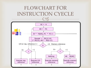
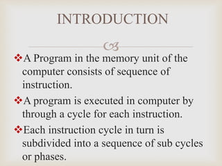
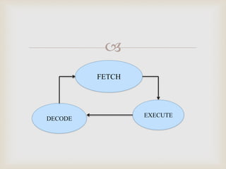
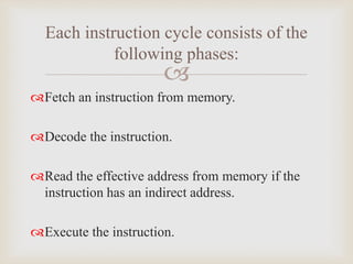
G.KARTHIGA
M.SC (INFO TECH)
DEPARTMENT OF CS & IT
NADAR SARASWATHI COLLEGE OF ARTS &
SCIENCE ,THENI.

A Program in the memory unit of the
computer consists of sequence of
instruction.
A program is executed in computer by
through a cycle for each instruction.
Each instruction cycle in turn is
subdivided into a sequence of sub cycles
or phases.
INTRODUCTION

FETCH
DECODE
EXECUTE

Fetch an instruction from memory.
Decode the instruction.
Read the effective address from memory if the
instruction has an indirect address.
Execute the instruction.
Each instruction cycle consists of the
following phases:

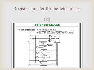
The program counter PC is loaded with the
address of the first instruction in the program.
The sequence counter SC is cleared to 0,providing
a decoded timing signal T0.
FETCH AND DECODE
T0:AR<-PC
T1:IR<-M[AR],PC<-PC+1
T2:D0……D7<-Decoder IR(12-14),AR<-IR(0-11),I<-IR(15)

Register transfer for the fetch phase

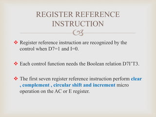
Place the content of PC onto the bus by making
the bus selection input s2,s1,s0 equal to 010.
Transfer the content of the bus to AR by enabling
the LD input of A.
T0 to achieve the following
connection:
T1:IR<-m[AR],PC<-PC+1
The timing signal that active after the decoding
is T3.
Decoder output D7 is equal to 1 if the operation
code is equal to binary bit 111.
The micro operation for the indirect address
condition can be symbolized by the register
transfer statement:
DETERMINE THE TYPE OF
INSTRUCTION
AR<-M[AR]

t
FLOWCHART FOR
INSTRUCTION CYECLE

 Register reference instruction are recognized by the
control when D7=1 and I=0.
 Each control function needs the Boolean relation D7I’T3.
 The first seven register reference instruction perform clear
, complement , circular shift and increment micro
operation on the AC or E register.
REGISTER REFERENCE
INSTRUCTION

Instruction cycle

  • 1.
    G.KARTHIGA M.SC (INFO TECH) DEPARTMENTOF CS & IT NADAR SARASWATHI COLLEGE OF ARTS & SCIENCE ,THENI.
  • 2.
     A Program inthe memory unit of the computer consists of sequence of instruction. A program is executed in computer by through a cycle for each instruction. Each instruction cycle in turn is subdivided into a sequence of sub cycles or phases. INTRODUCTION
  • 3.
  • 4.
     Fetch an instructionfrom memory. Decode the instruction. Read the effective address from memory if the instruction has an indirect address. Execute the instruction. Each instruction cycle consists of the following phases:
  • 5.
     The program counterPC is loaded with the address of the first instruction in the program. The sequence counter SC is cleared to 0,providing a decoded timing signal T0. FETCH AND DECODE T0:AR<-PC T1:IR<-M[AR],PC<-PC+1 T2:D0……D7<-Decoder IR(12-14),AR<-IR(0-11),I<-IR(15)
  • 6.
  • 7.
     Place the contentof PC onto the bus by making the bus selection input s2,s1,s0 equal to 010. Transfer the content of the bus to AR by enabling the LD input of A. T0 to achieve the following connection: T1:IR<-m[AR],PC<-PC+1
  • 8.
    The timing signalthat active after the decoding is T3. Decoder output D7 is equal to 1 if the operation code is equal to binary bit 111. The micro operation for the indirect address condition can be symbolized by the register transfer statement: DETERMINE THE TYPE OF INSTRUCTION AR<-M[AR]
  • 9.
  • 10.
      Register referenceinstruction are recognized by the control when D7=1 and I=0.  Each control function needs the Boolean relation D7I’T3.  The first seven register reference instruction perform clear , complement , circular shift and increment micro operation on the AC or E register. REGISTER REFERENCE INSTRUCTION