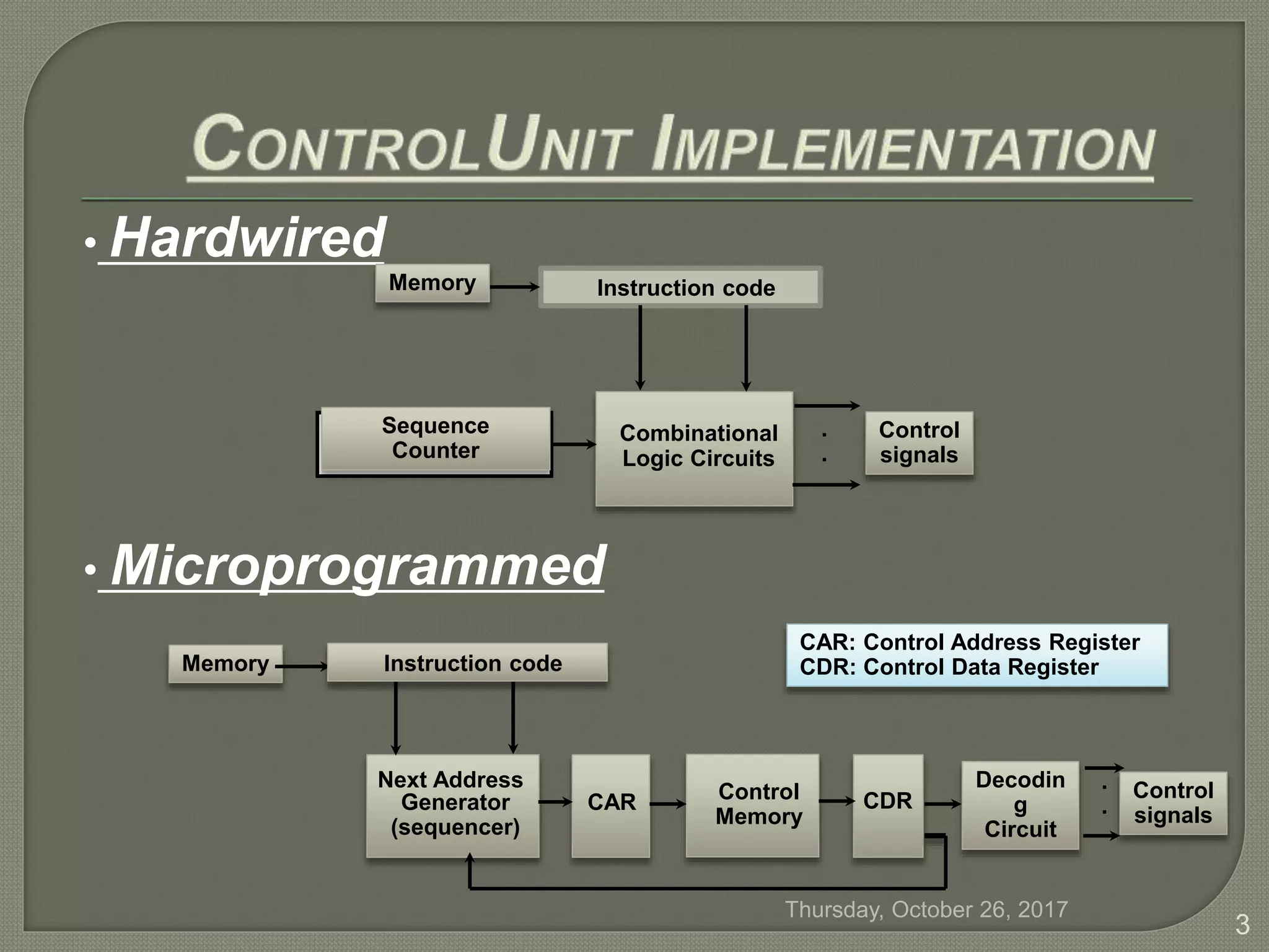
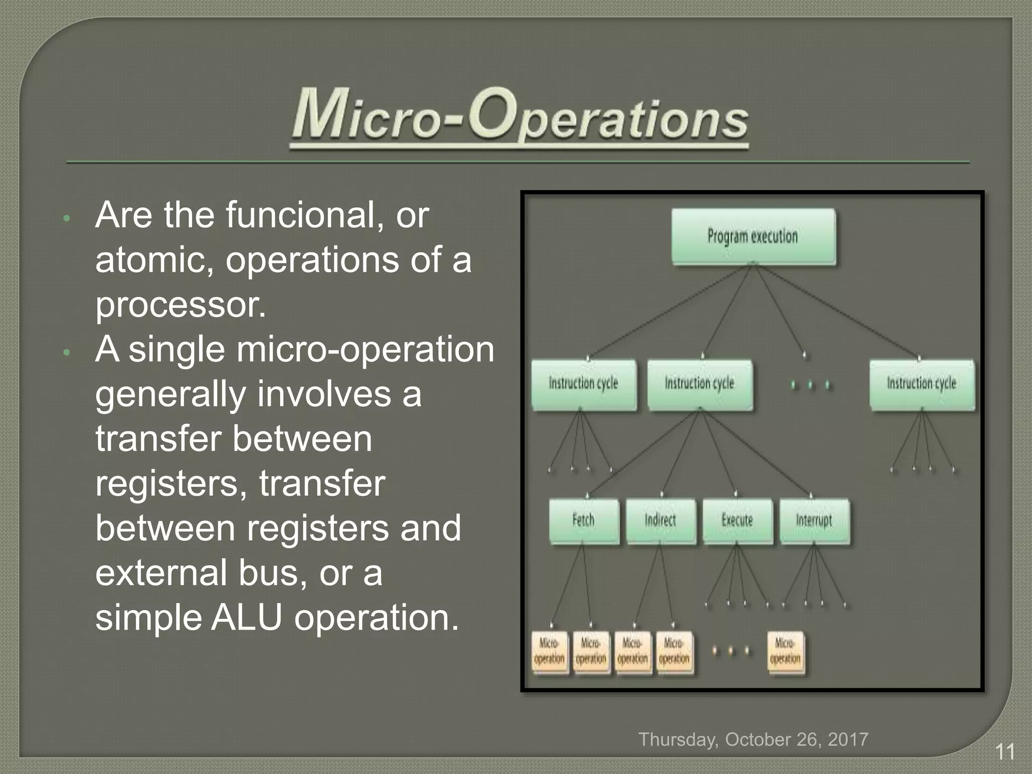
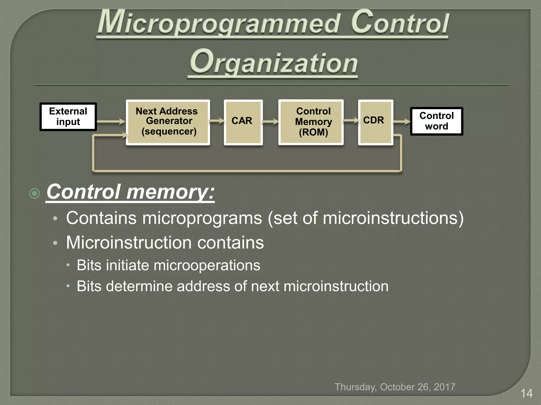
The document discusses the components and functions of a computer's control unit within the CPU, highlighting the differences between hardwired and microprogrammed control mechanisms. It explains control signals, control memory, micro-instructions, and their role in executing computer instructions through routines and subroutines. Additionally, it describes the sequencing capabilities required for address handling and branching in instruction execution.


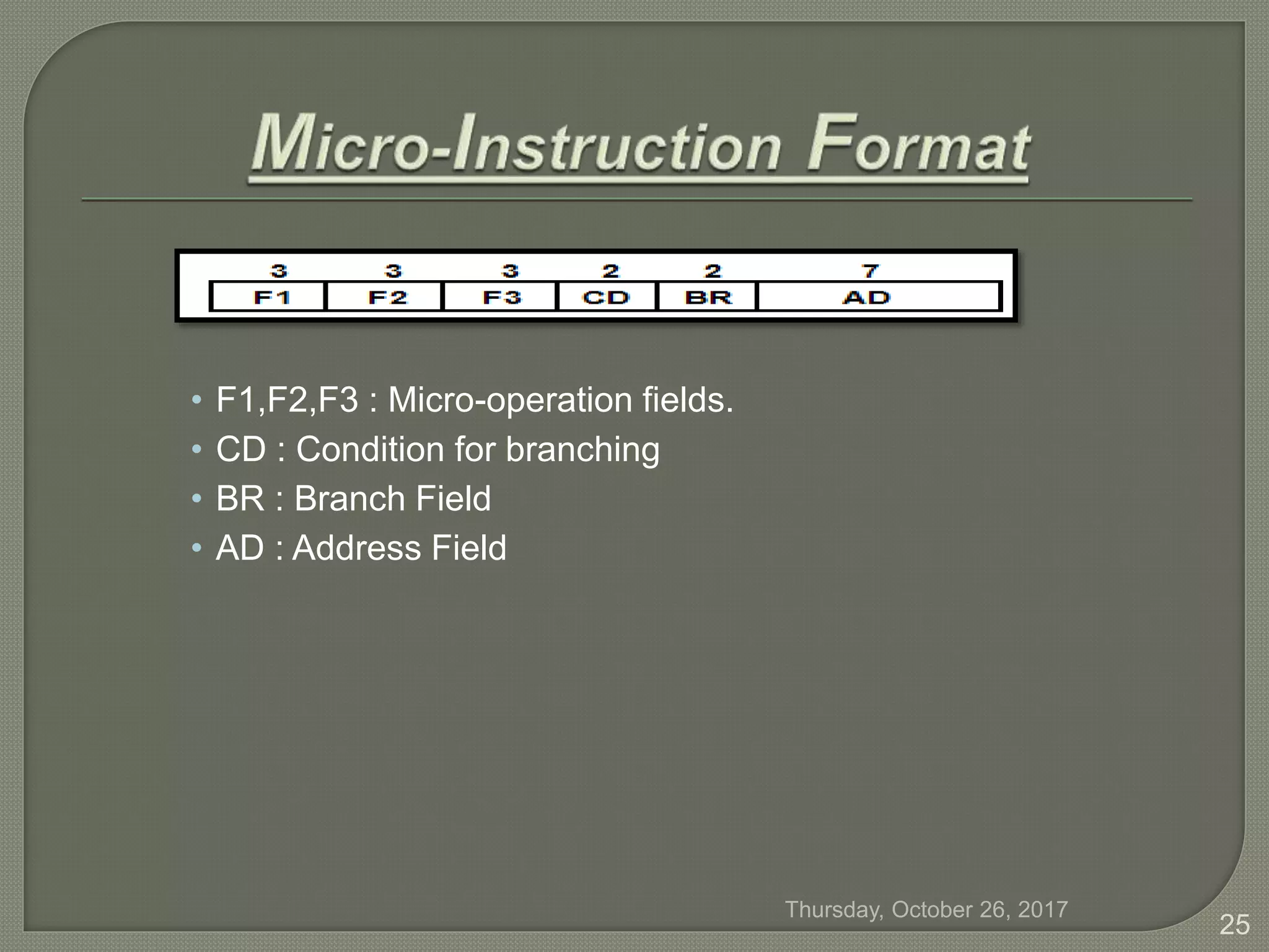
![ Computer instruction format:
Four computer instructions:
(EA is Effective Address)
I Opcode Address
15 14 11 10 0
ADD 0000 AC AC + M[EA]
BRANCH 0001 if (AC < 0) then (PC EA)
STORE 0010 M[EA] AC
EXCHANGE 0011 AC M[EA], M[EA] AC
Symbol OP-code Description
Thursday, October 26, 2017
24](https://image.slidesharecdn.com/computerartitecture-171026193002/75/MicroProgrammed-Explained-24-2048.jpg)