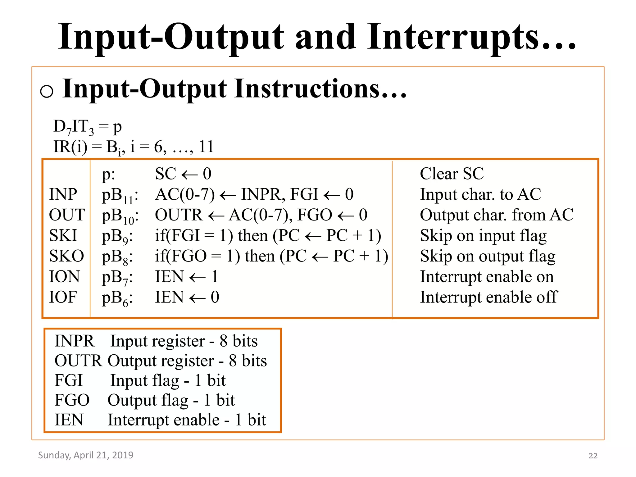
Downloaded 186 times

![Instruction Cycle…
o Fetch and Decode
Sunday, April 21, 2019 15
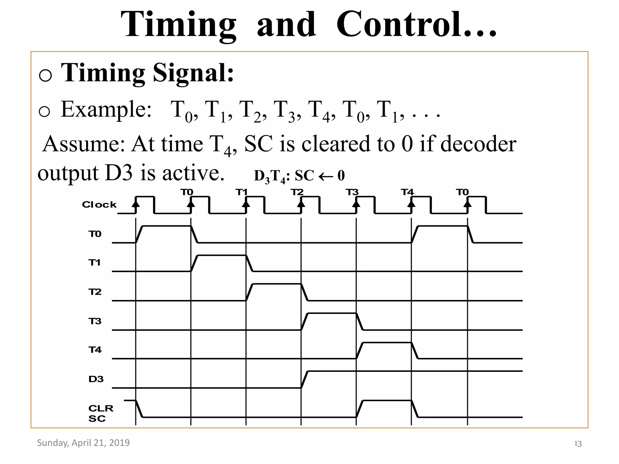
T0: AR PC (S0S1S2=010, T0=1)
T1: IR M [AR], PC PC + 1 (S0S1S2=111, T1=1)
T2: D0, . . . , D7 Decode IR(12-14), AR IR(0-11), I IR(15)](https://image.slidesharecdn.com/morrismanochapterfive-190421122612/75/Basic-Computer-Organization-and-Design-15-2048.jpg)
![Instruction Cycle…
o Determine the Type of Instruction
Sunday, April 21, 2019 16
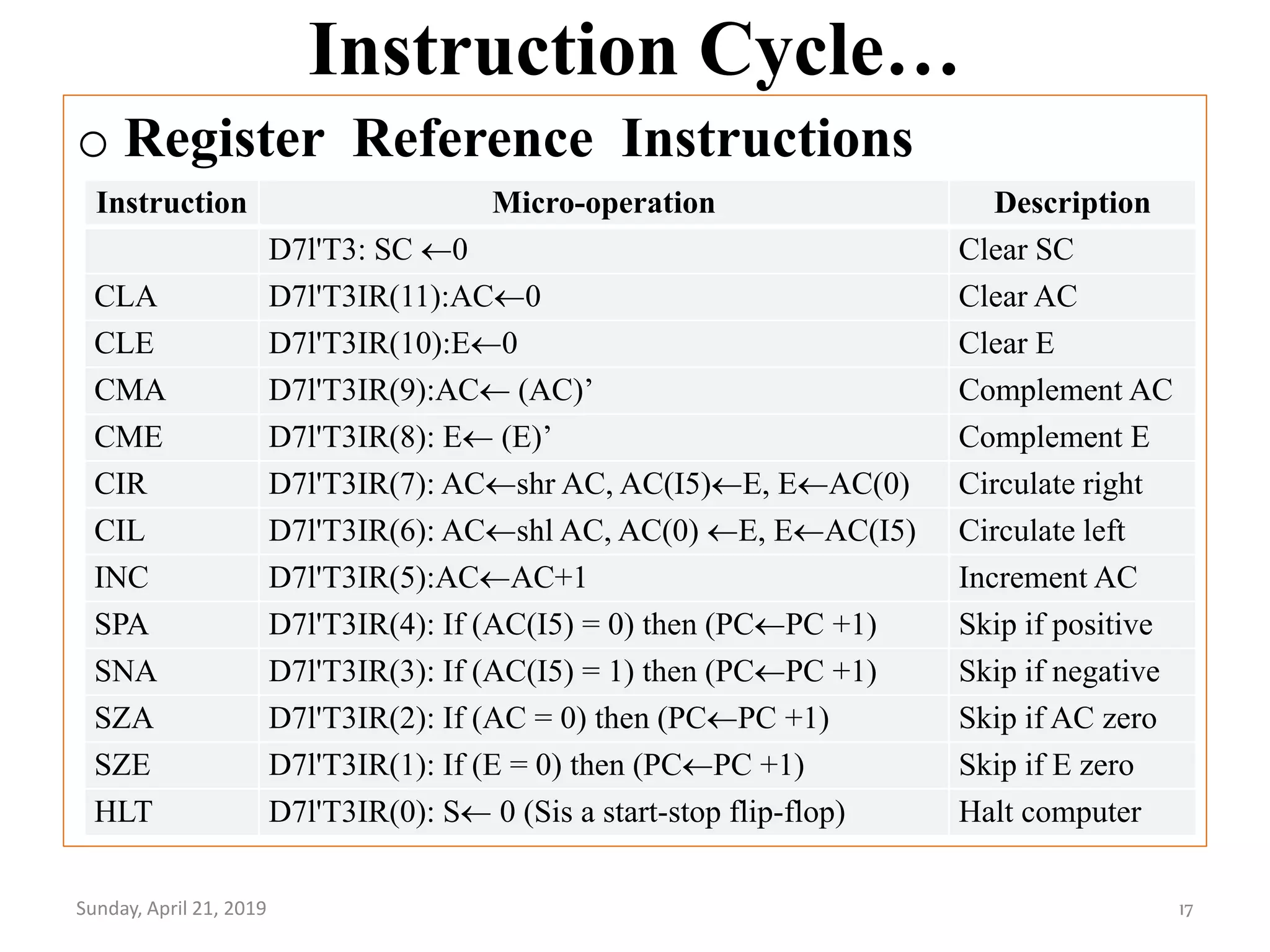
D'7IT3: AR M[AR]
D'7I'T3: Nothing
D7I'T3: Execute a register-reference instr.
D7IT3: Execute an input-output instr.](https://image.slidesharecdn.com/morrismanochapterfive-190421122612/75/Basic-Computer-Organization-and-Design-16-2048.jpg)
![Instruction Cycle…
o Memory Reference Instruction
Sunday, April 21, 2019 18
Symbol
Operation
Decoder Symbolic Description
AND D0 AC AC M[AR]
ADD D1 AC AC + M[AR], E Cout
LDA D2 AC M[AR]
STA D3 M[AR] AC
BUN D4 PC AR
BSA D5 M[AR] PC, PC AR + 1
ISZ D6 M[AR] M[AR] + 1, if M[AR] + 1 = 0 then PC PC+1
AND to AC
D0T4: DR M[AR] Read operand
D0T5: AC AC DR, SC 0 AND with AC
ADD to AC
D1T4: DR M[AR] Read operand
D1T5: AC AC + DR, E Cout, SC 0 Add to AC and store carry in E](https://image.slidesharecdn.com/morrismanochapterfive-190421122612/75/Basic-Computer-Organization-and-Design-18-2048.jpg)
![Instruction Cycle…
o Memory Reference Instruction…
Sunday, April 21, 2019 19
LDA: Load to AC
D2T4: DR M[AR]
D2T5: AC DR, SC 0
STA: Store AC
D3T4: M[AR] AC, SC 0
BUN: Branch Unconditionally
D4T4: PC AR, SC 0
BSA: Branch and Save Return Address
M[AR] PC, PC AR + 1
D5T4: M[AR] PC, AR AR + 1
D5T5: PC AR, SC 0
ISZ: Increment and Skip-if-Zero
D6T4: DR M[AR]
D6T5: DR DR + 1
D6T4: M[AR] DR, if (DR = 0) then (PC PC + 1), SC 0](https://image.slidesharecdn.com/morrismanochapterfive-190421122612/75/Basic-Computer-Organization-and-Design-19-2048.jpg)


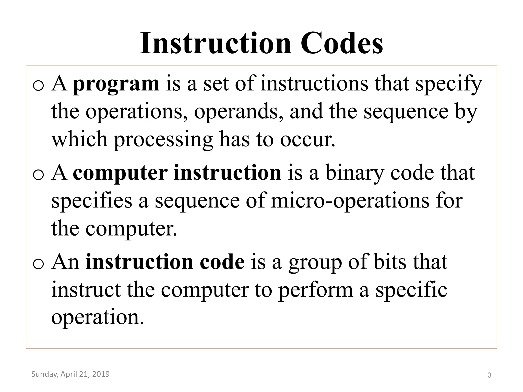
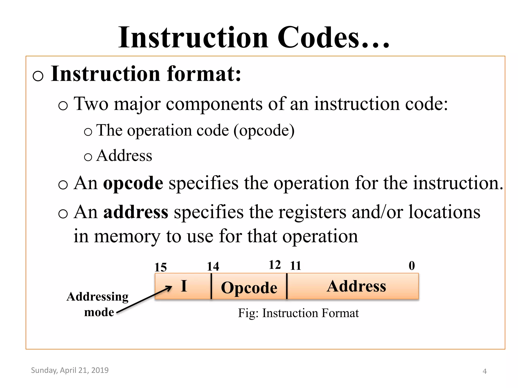
The document provides an overview of basic computer organization and design, focusing on instruction codes, computer registers, instruction types, and the instruction cycle. It describes the components of instruction codes, the roles of opcodes and addresses, various instruction formats, and how control units generate necessary signals. Additionally, it covers input/output operations and interrupt handling in a basic computer architecture.