Downloaded 397 times

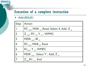
![Basic concepts Fetching a word from memory ; move (R1),R2 MAR [ R1] Start a read operation on the memory bus Wait for MFC response from the memory Load MDR from the memory bus R2 [MDR ] To accommodate the variability in response time, the processor waits until it receives an indication that the requested read operation is completed ,such a signal is the MFC signal](https://image.slidesharecdn.com/unit2-controlunit-111106021153-phpapp02/85/Unit2-control-unit-9-320.jpg)


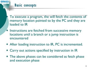
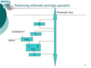
Computer organization involves fetching instructions from memory and executing them. There are two main approaches to implementing the control unit: hardwired control and microprogrammed control. Hardwired control uses combinational logic to generate control signals based on the instruction and state, while microprogrammed control stores control sequences as microinstructions in a separate control store.