Download as PDF, PPTX

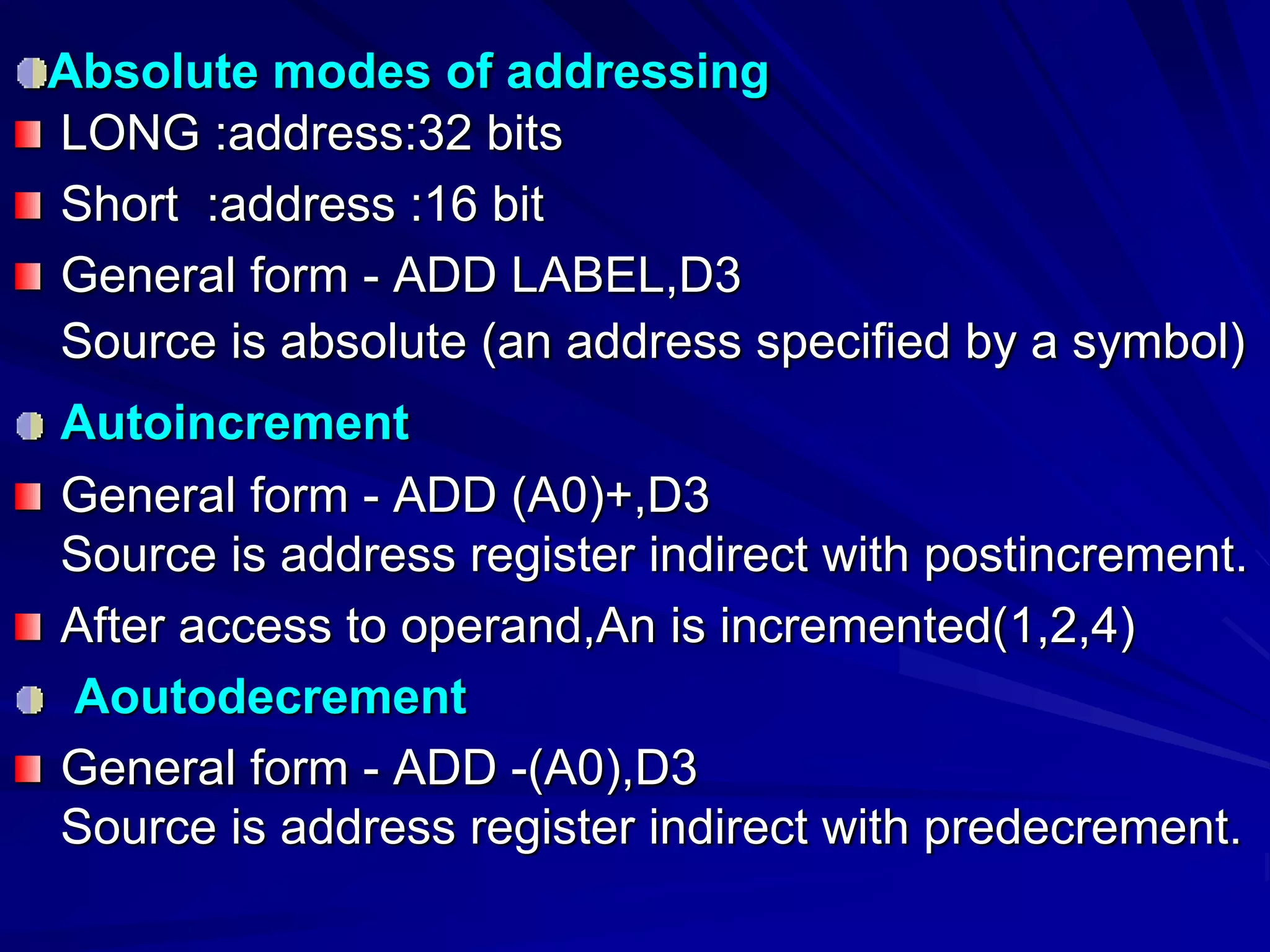
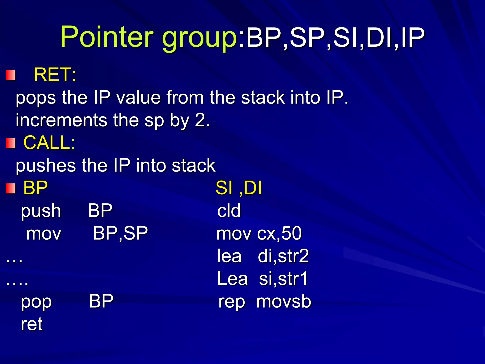
![instructions
One operand and two operand
two operand: OP src,dst
Ex: add #9,d3
dst [src]+[dst]
Source op or destination op must be in Dn
Second op:register or memory location](https://image.slidesharecdn.com/processors-150829185042-lva1-app6891/75/16-bit-microprocessors-7-2048.jpg)
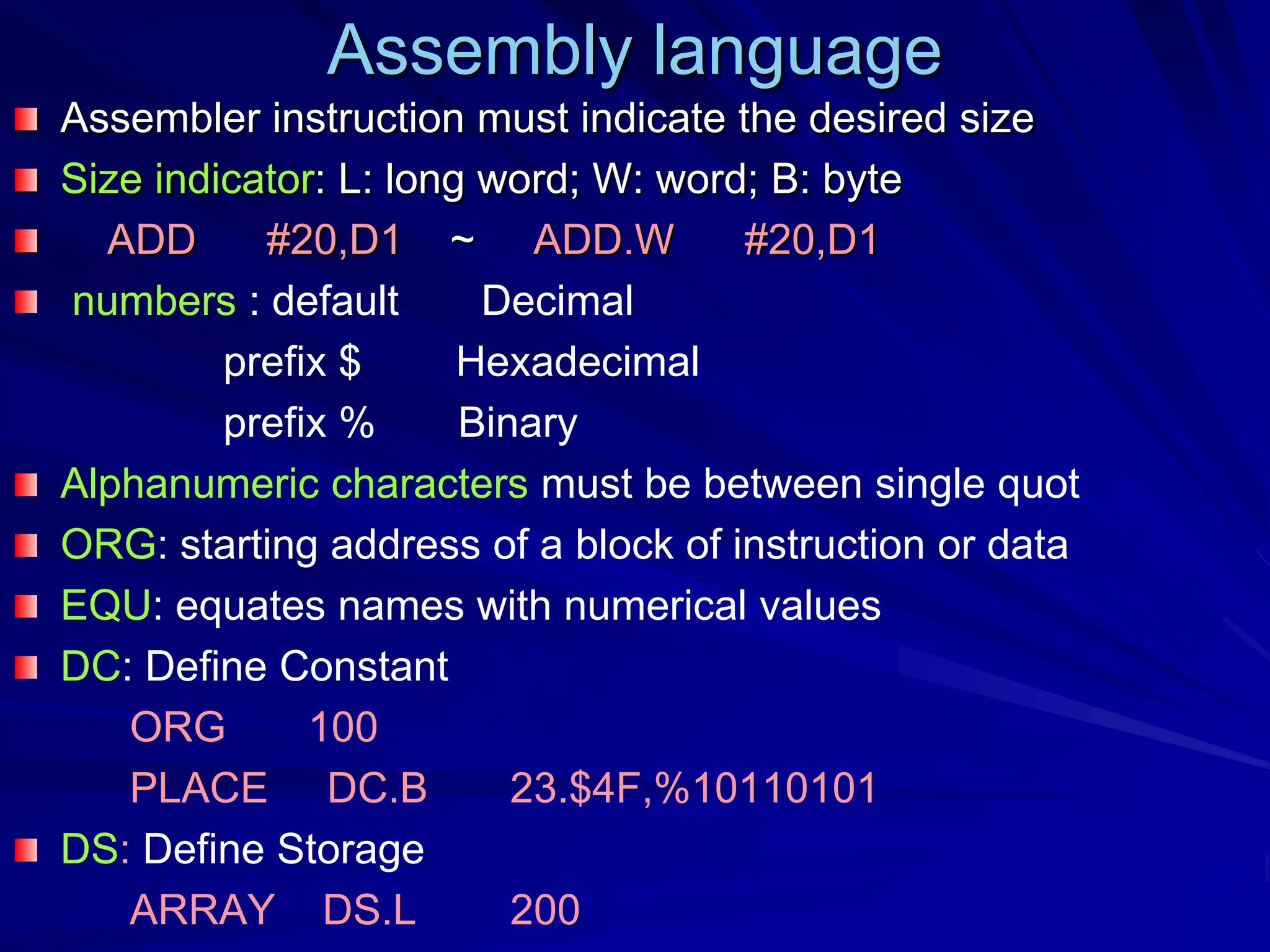
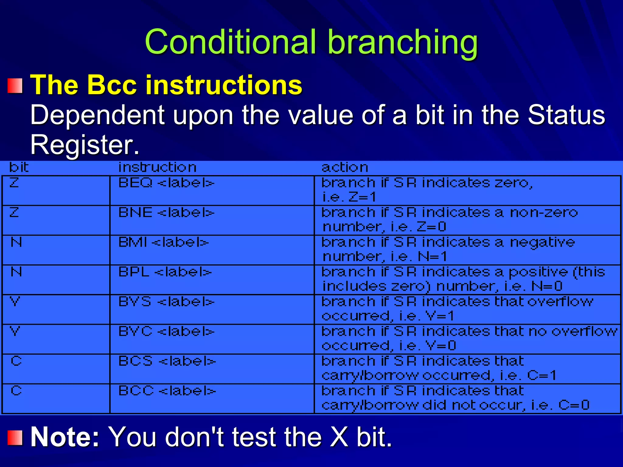
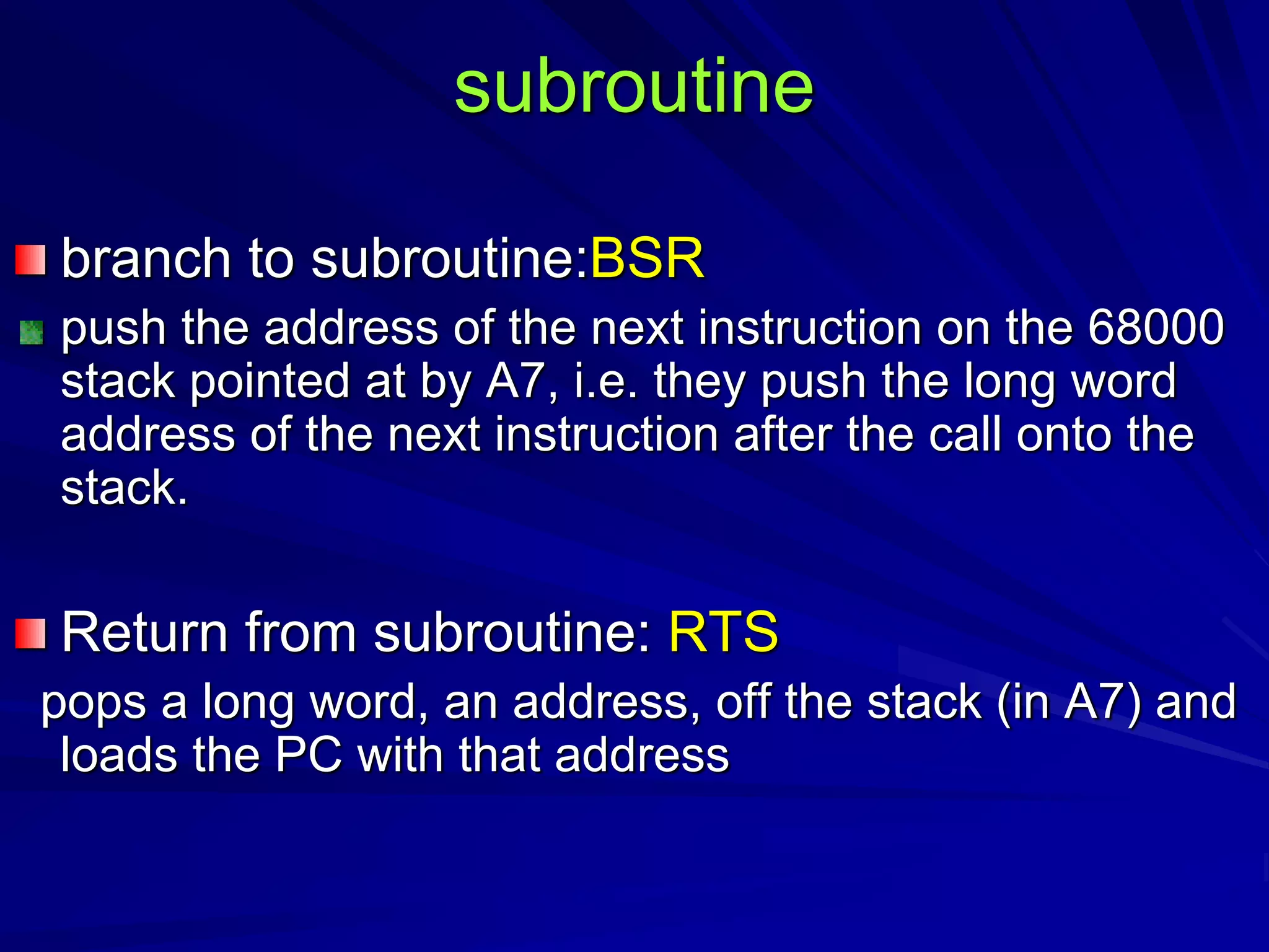
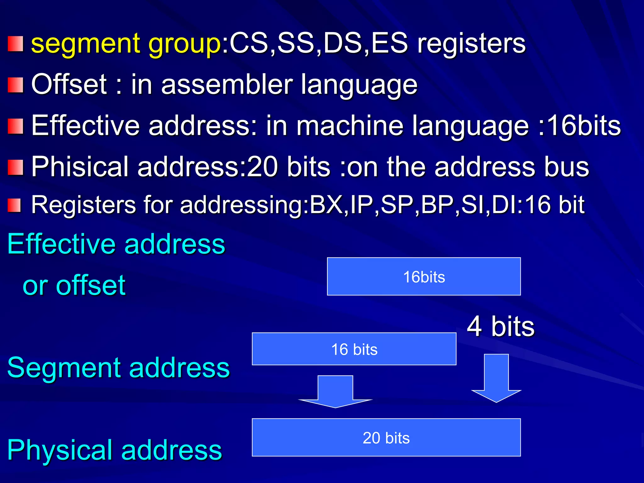
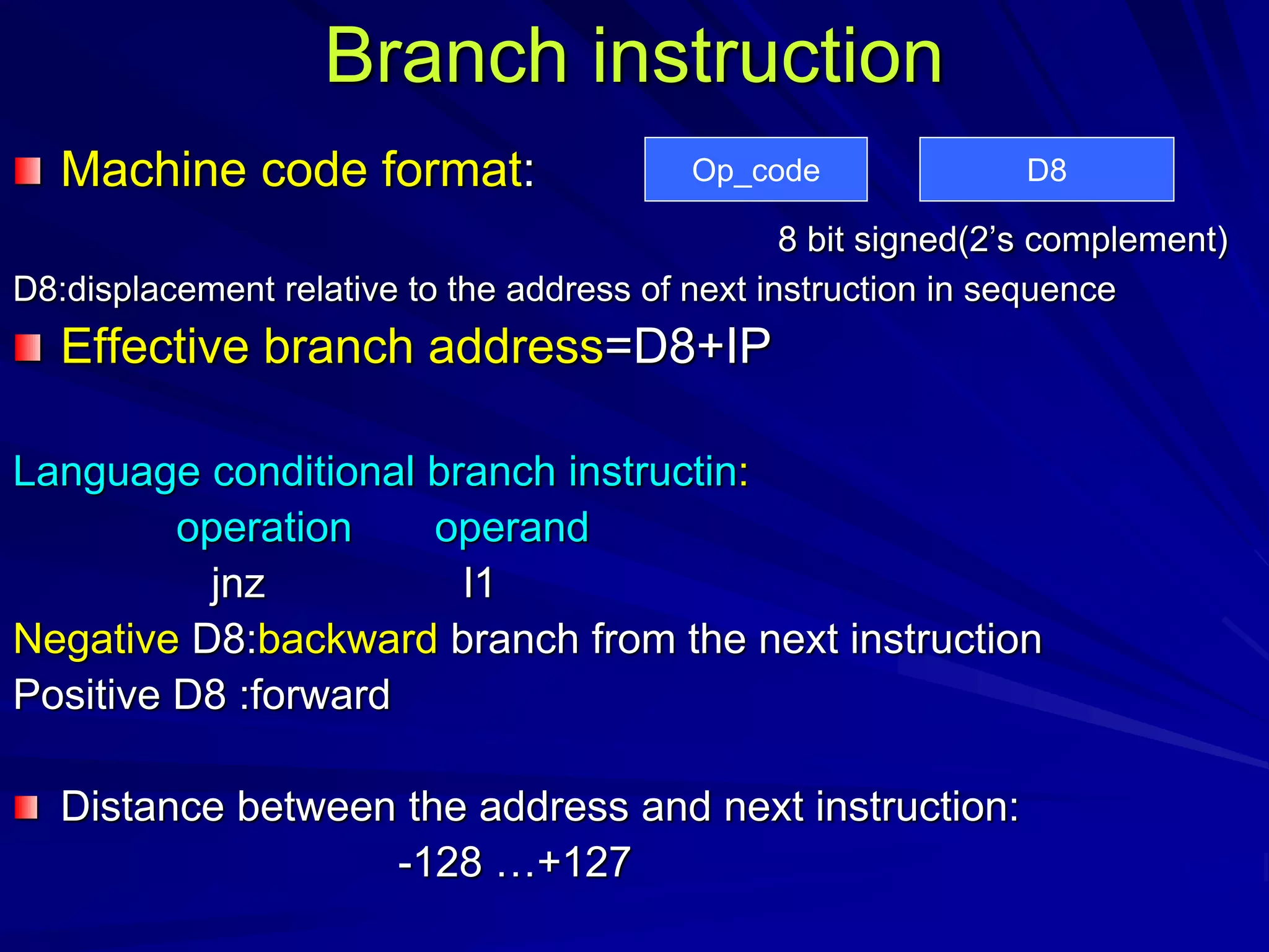
![Branch instruction)conditional)
Branch address=[updated PC]+ offset
Offset: the distance from the word that follows the branch
instruction op_code word
8 bit offset : 8 bit in op_code :+127…-128 bytes
16 bit offset :+32… -32 k
1000 LOOP ADD.W (A2)+,D0
1002 SUB.W #1,D1
1004 BGT LOOP
1006
Op_code offset
Op_code word
Op_code word
Op code -6](https://image.slidesharecdn.com/processors-150829185042-lva1-app6891/75/16-bit-microprocessors-14-2048.jpg)
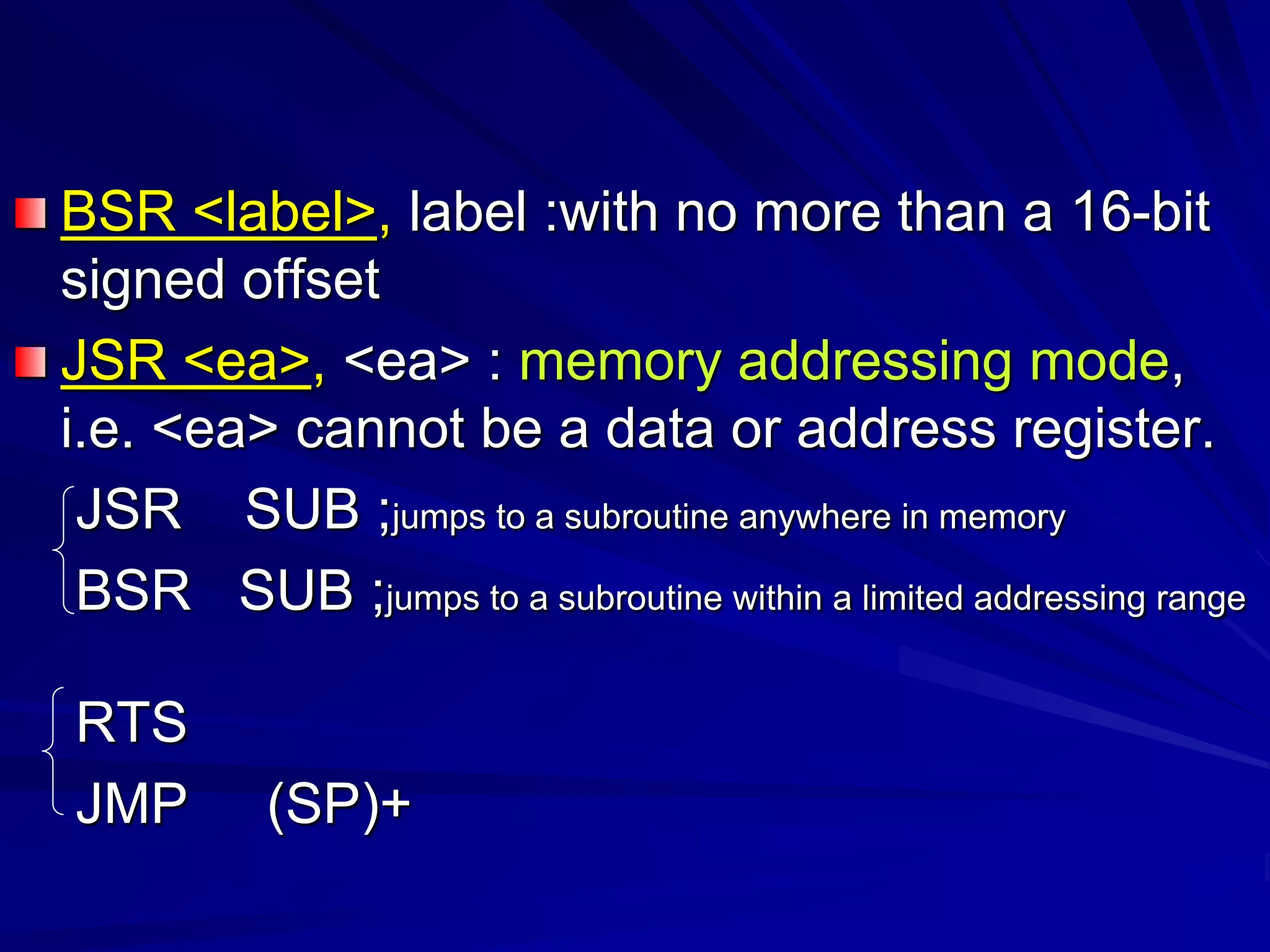
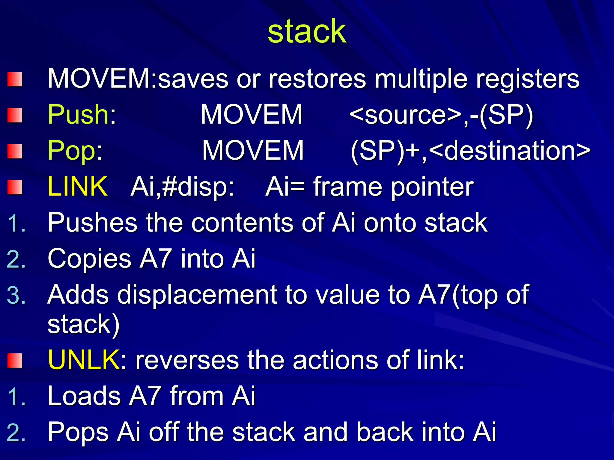
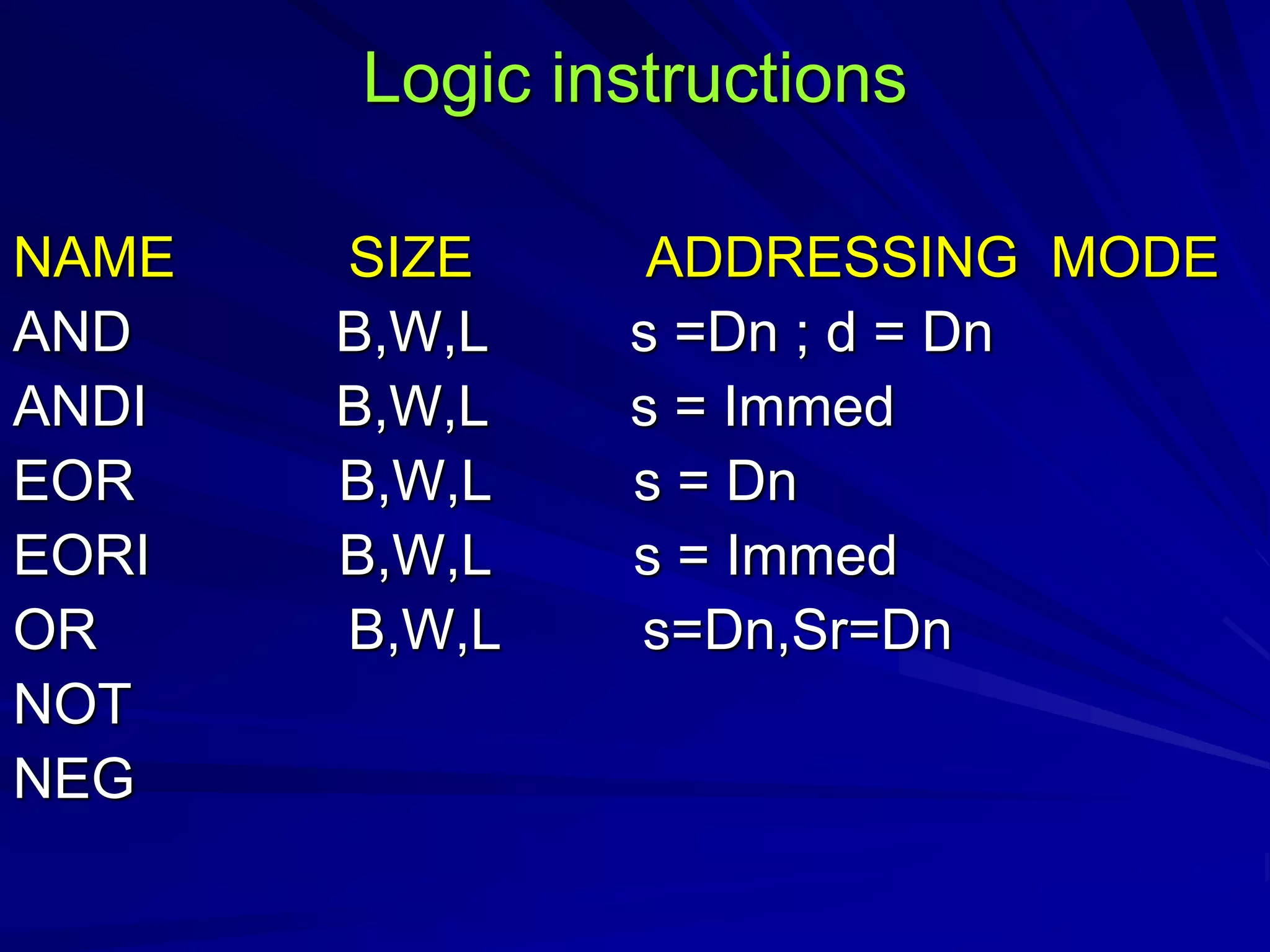
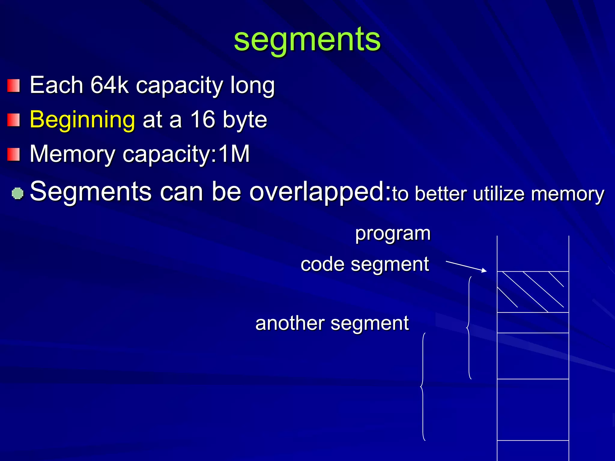
![…
MOVE.L P2,-(A7)
MOVE.L P1,-(A7)
BSR SUB1
2014 MOVE.L (A7),RES [D0]
ADDI.L #8,A7 [D1]
… [D2]
2100 SUB1 LINK A6,#0 [A0]
MOVEM.L D0-D2/A0,A7 [A6]
MOVEA.L 8(A6),A0 2014
… P1
UNLK A6 P2
RTS](https://image.slidesharecdn.com/processors-150829185042-lva1-app6891/75/16-bit-microprocessors-23-2048.jpg)
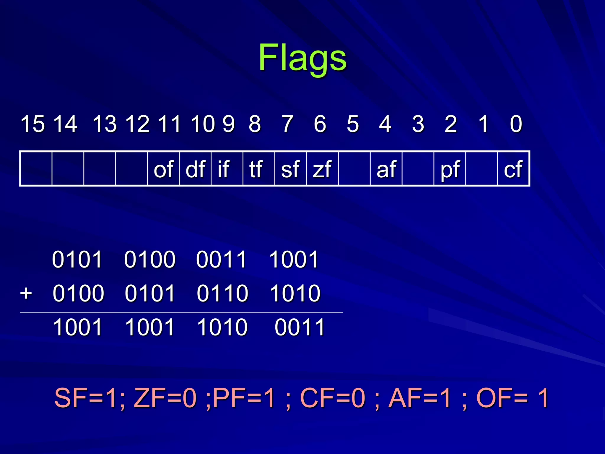
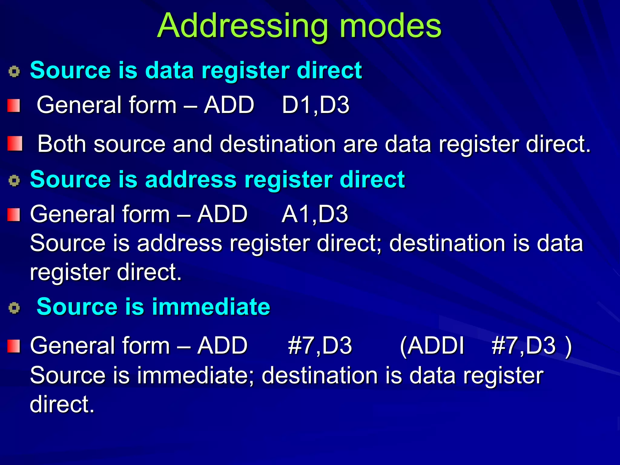
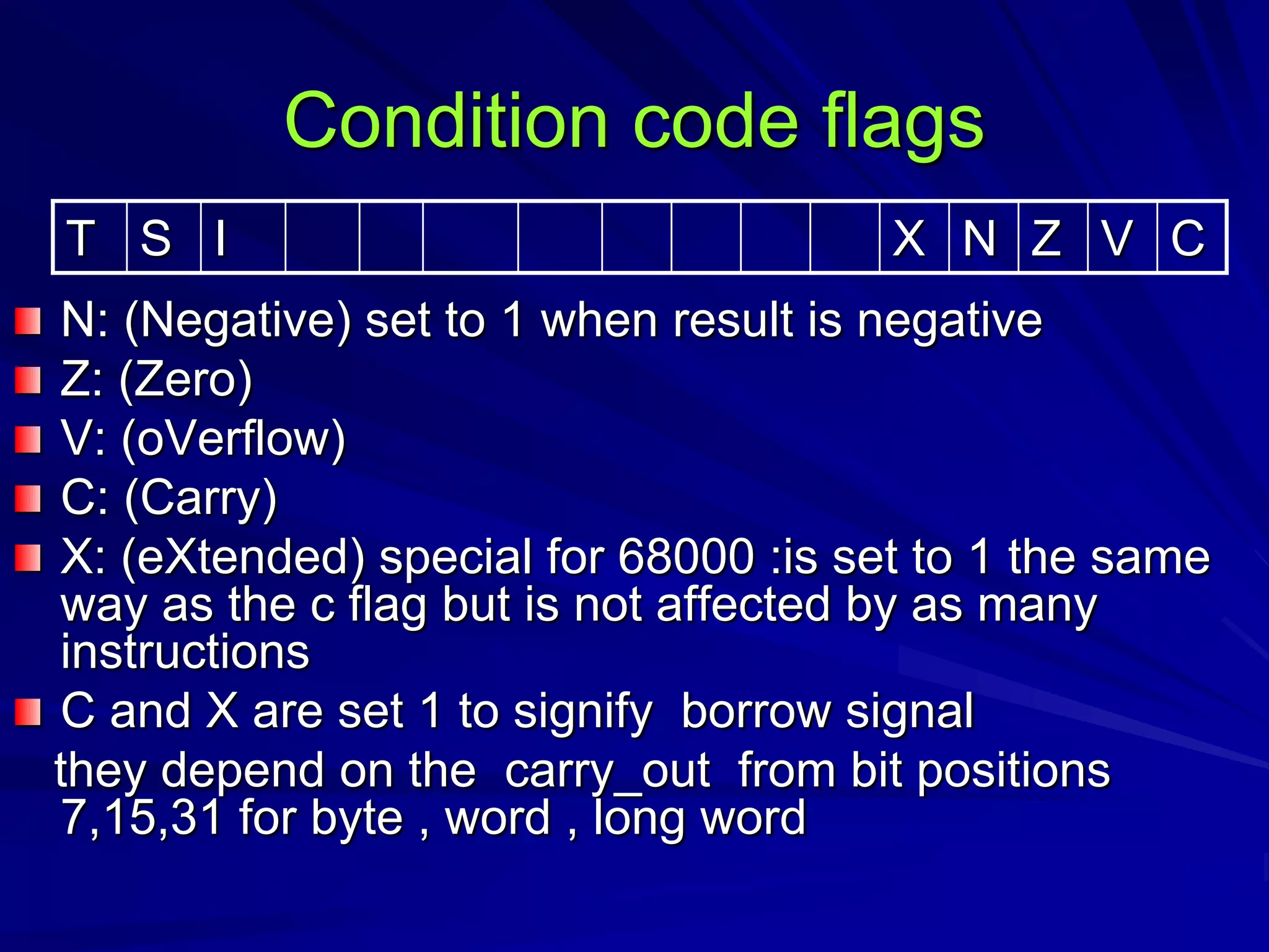
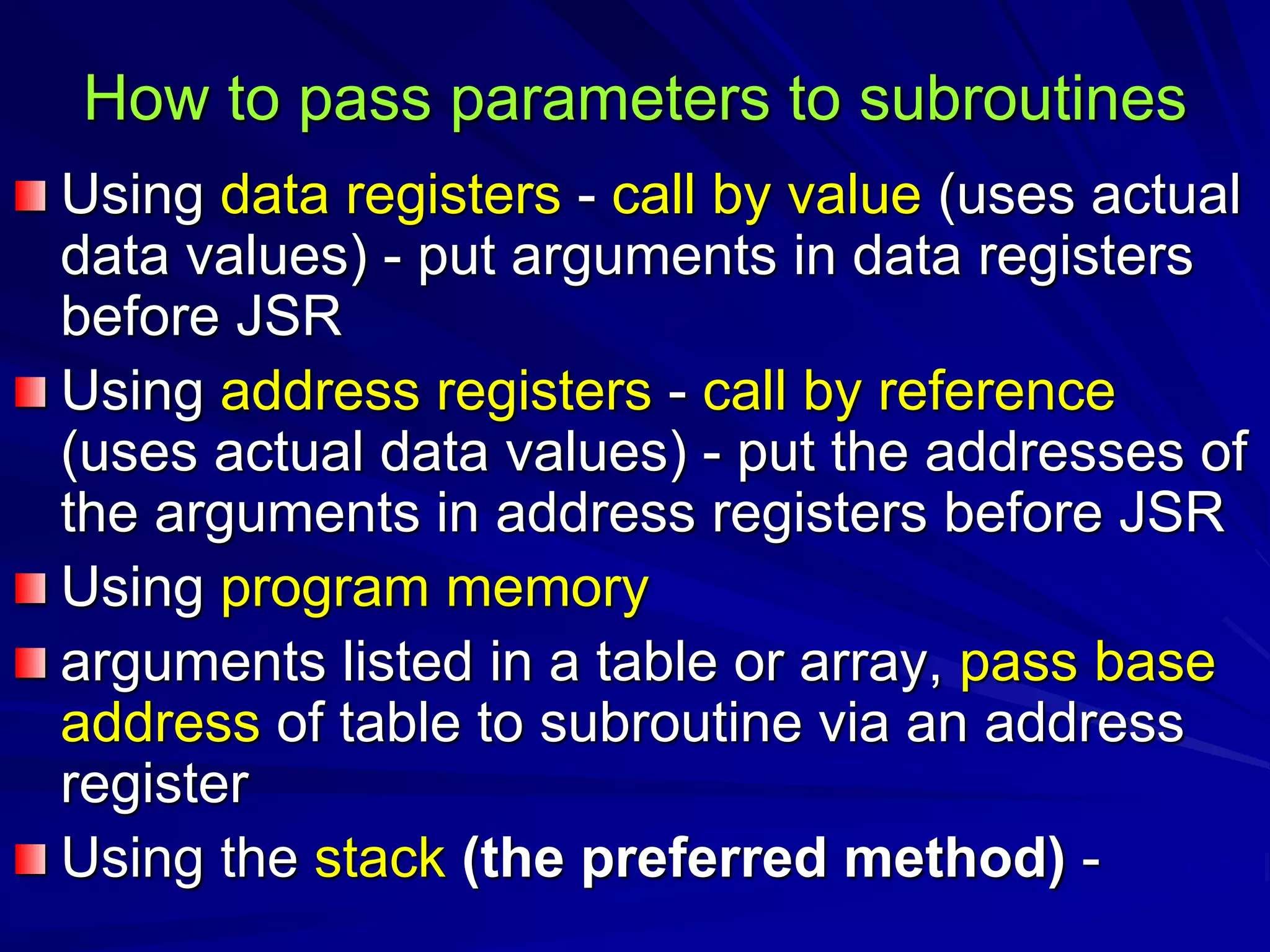
![Addressing modes
Instruction instruction memory instruction register
a) Immediate b) direct c) register
Mov ax,50 mov ax,place mov ax,bx
Instruction register memory
d) register indirect EA= BX
DI,SI
mov bx,offset place
mov ax,[bx]
datum EA datum register datum
register EA datum](https://image.slidesharecdn.com/processors-150829185042-lva1-app6891/75/16-bit-microprocessors-31-2048.jpg)
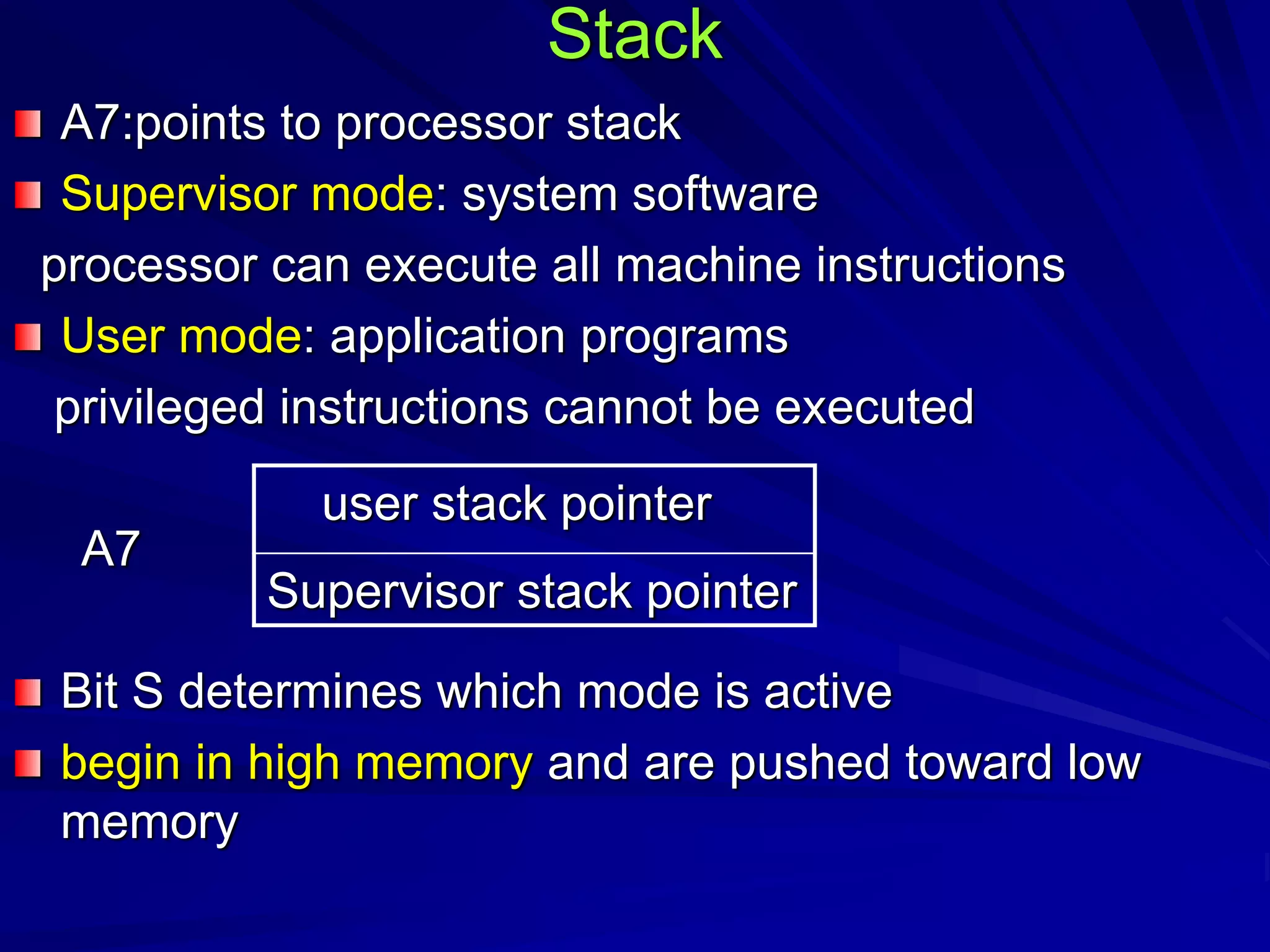
![Addressing modes
instruction
memory
EA
register
mov al,list+1
e) register relative
instruction register
index:si,di
base:bp,bx
register
f) based index
mov al,[bx+si]
address
+
datum
register displacement
Base reg. displacement
Base address
+ datum
index](https://image.slidesharecdn.com/processors-150829185042-lva1-app6891/75/16-bit-microprocessors-32-2048.jpg)
![g)relative base address
BX SI
mov al,[bx+si+3] EA= BP + DI + displacement
index
Base addr
+
Base reg Index reg displacement
datum](https://image.slidesharecdn.com/processors-150829185042-lva1-app6891/75/16-bit-microprocessors-33-2048.jpg)
![Example:
0050 AGAIN: INC CX
0052 ADD AX,[BX]
0054 JNZ AGAIN
0056 NEXT: MOV RESULT,CX
0050 effective branch address
- 0056 (IP)when jnz branch decision is made
-6](https://image.slidesharecdn.com/processors-150829185042-lva1-app6891/75/16-bit-microprocessors-35-2048.jpg)
![Name addressing symbol addressing function
Immediate #value operand=value
Absolute short value EA=sign extended w value
Absolute long value EA=value
Register Rn EA=Rn
Register indirect (An) EA=[An]
Autoincrement (An)+ EA=[An]
Auodecrement (An)- EA=[An]
Indexed basic w value (An) EA=w value +[An]
Indexed full w value (An,Rk,s) EA=B value +[An]+[Rk]
relative basic w value or label EA=w value +[pc]
Relative full B value (pc,Rk,s) EA=B value +[pc]+[Rk]](https://image.slidesharecdn.com/processors-150829185042-lva1-app6891/75/16-bit-microprocessors-38-2048.jpg)

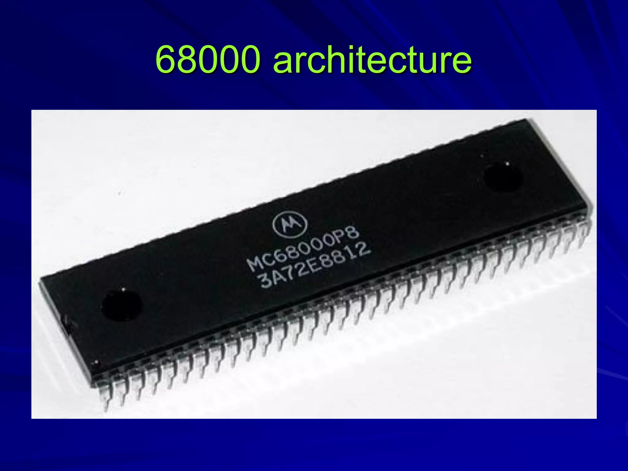
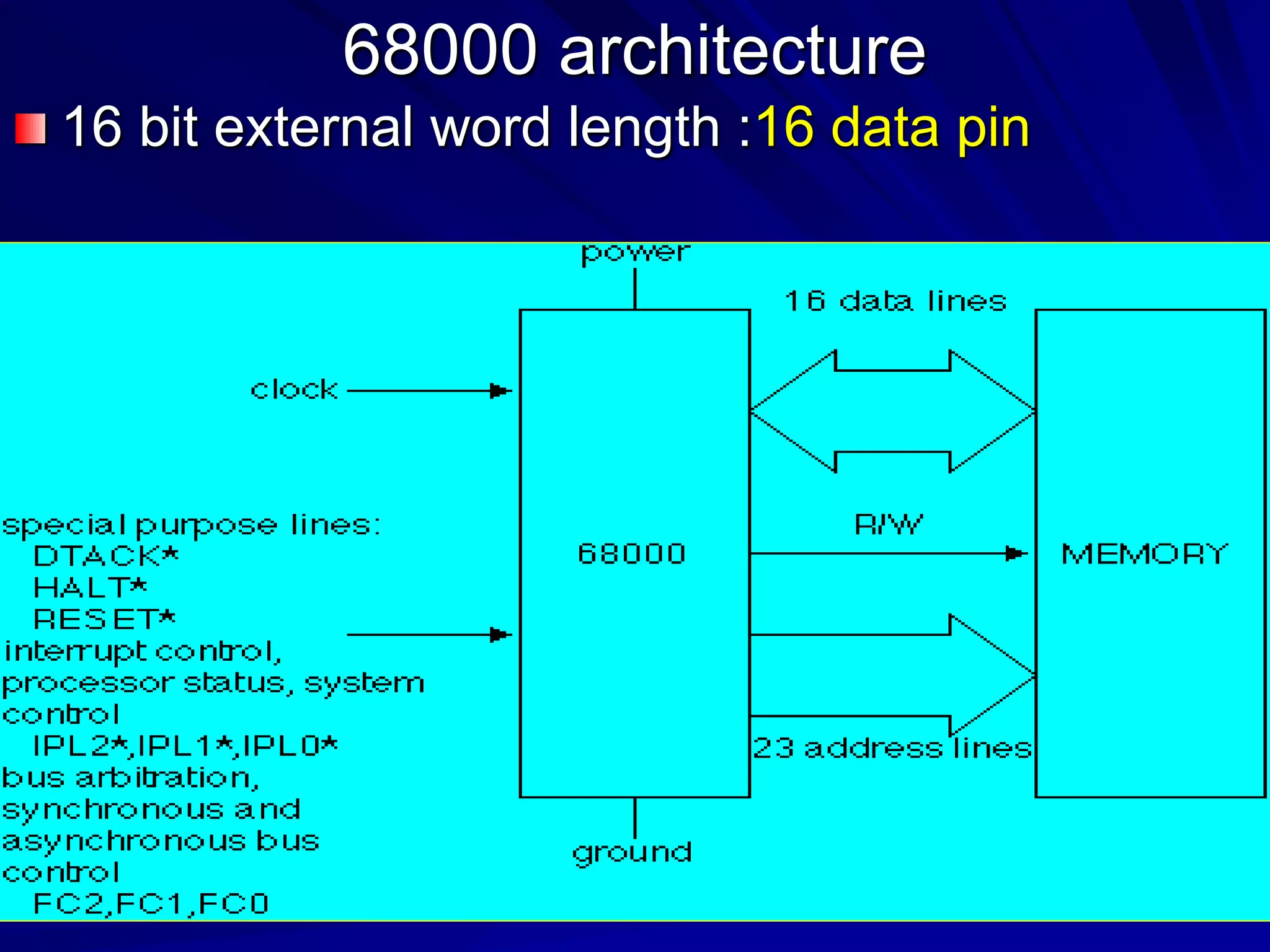
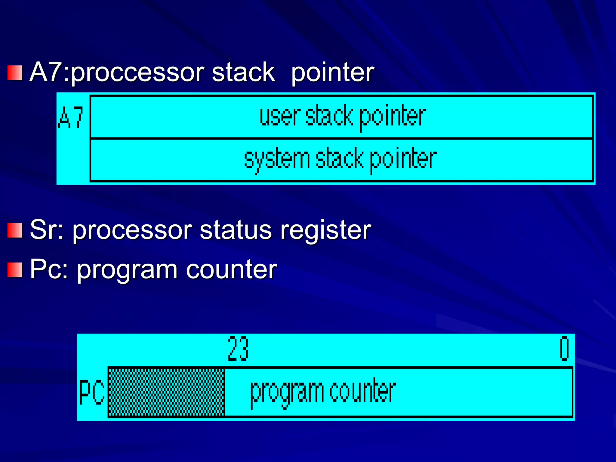
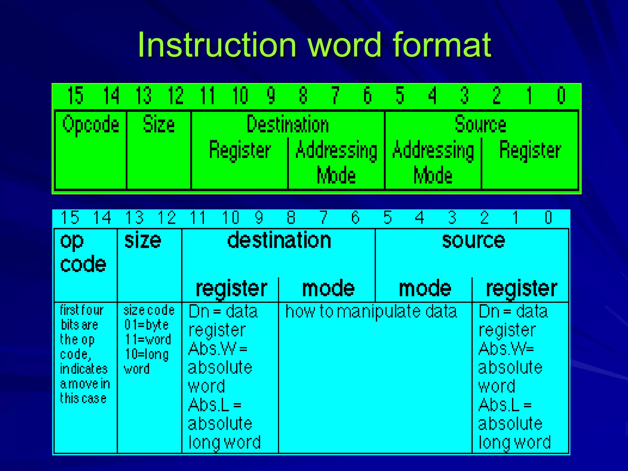
This document discusses the 16-bit 68000 microprocessor architecture. It describes the 68000's 16-bit external data bus, 32-bit registers including 8 data registers and 7 address registers. It covers the register organization, 24-bit address space of 16MB, and functions of registers like the program counter, stack pointer, and status register. The document explains the instruction word format and different instruction types. It details the addressing modes like direct, register indirect, autoincrement, autodecrement, and absolute. Assembly language syntax and directives like ORG, EQU, and DS are outlined. Logic instructions, condition codes, conditional and unconditional branching, subroutines, and the stack are summarized. The document also provides