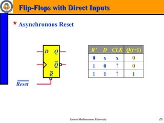
The document covers digital logic design, specifically synchronous sequential logic and its components such as latches and flip-flops. It explains various types of sequential circuits, including their operation, state equations, and characteristic tables. Additionally, it discusses controlled latches, the differentiation between edge-triggered and level-triggered devices, and the analysis of clocked sequential circuits.


![Eastern Mediterranean University
Eastern Mediterranean University 34
34
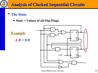
Analysis of Clocked Sequential Circuits
Analysis of Clocked Sequential Circuits
State Equations
D Q
Q
CLK
D Q
Q
A
B
y
x
A(t+1) = DA
= A(t) x(t)+B(t) x(t)
= A x + B x
B(t+1) = DB
= A’(t) x(t)
= A’ x
y(t) = [A(t)+ B(t)] x’(t)
= (A + B) x’](https://image.slidesharecdn.com/chapter5synchronoussequentialcircuit-241126214637-731aaf16/85/Chapter_5_Synchronous_Sequential_Circuit-ppt-34-320.jpg)


![Attack surfaces and attack tress[inform]](https://cdn.slidesharecdn.com/ss_thumbnails/lecture03-260108015941-a4dee53b-thumbnail.jpg?width=640&height=640&fit=bounds)


