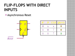
The document discusses synchronous sequential logic in digital logic design, focusing on the function and utility of flip-flops with asynchronous inputs, specifically preset and clear commands. It covers the analysis of clocked sequential circuits, including state equations, transition tables, and state diagrams, illustrating the interactions between present state, input, next state, and output. Examples using D flip-flops are provided to demonstrate how inputs affect the state transitions in digital circuits.


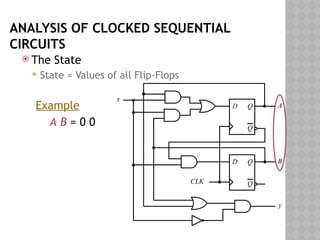
![ANALYSIS OF CLOCKED SEQUENTIAL
CIRCUITS
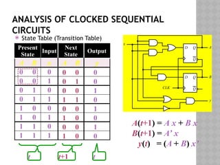
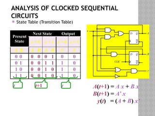
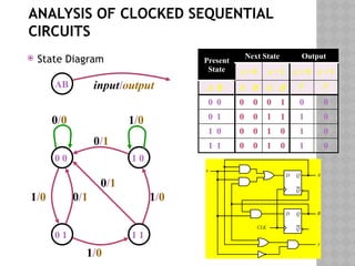
State Equations
D Q
Q
CLK
D Q
Q
A
B
y
x
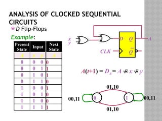
A(t+1) = DA
= A(t) x(t)+B(t) x(t)
= A x + B x
B(t+1) = DB
= A’(t) x(t)
= A’ x
y(t) = [A(t)+ B(t)] x’(t)
= (A + B) x’](https://image.slidesharecdn.com/lec25-26-241001175405-9978f7da/85/Digital-Logic-Design-Synchronous-logic-circuits-7-320.jpg)