Downloaded 767 times
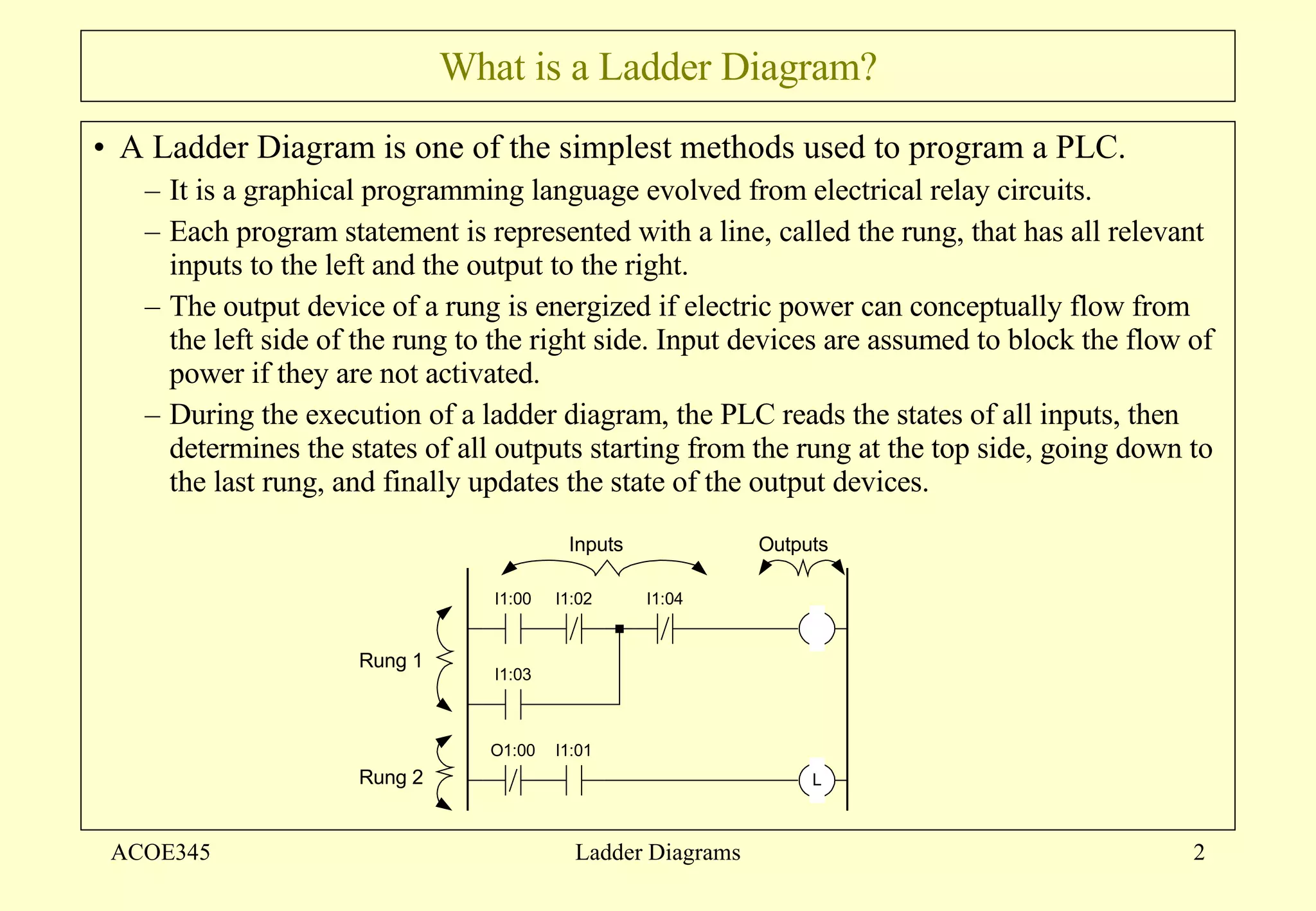
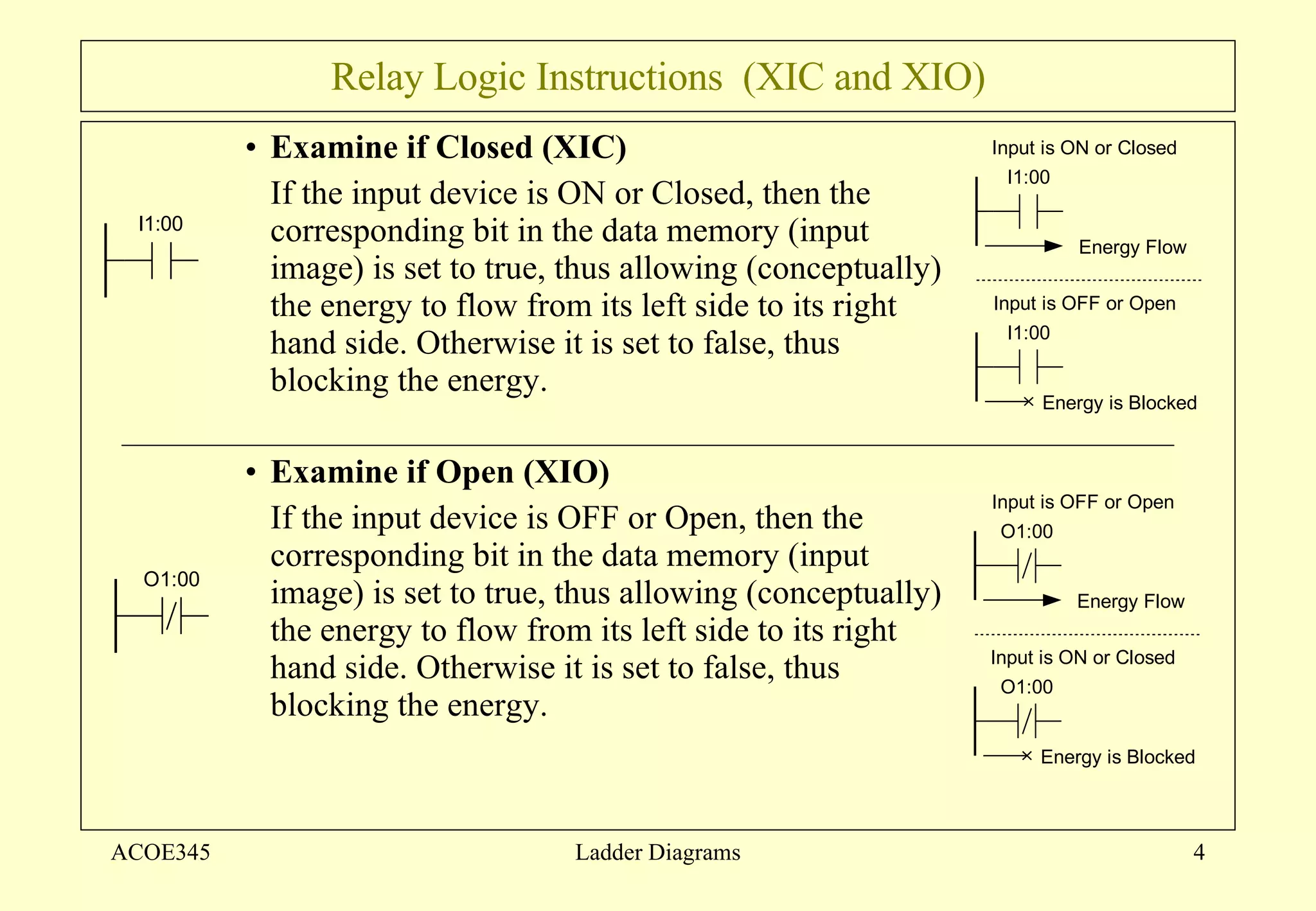
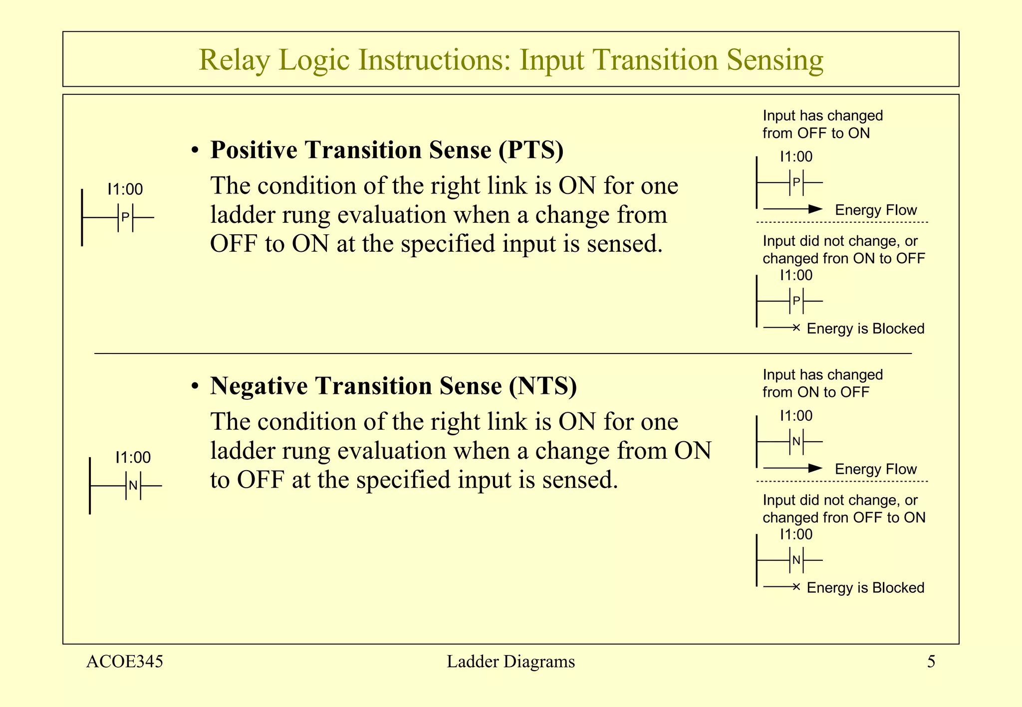
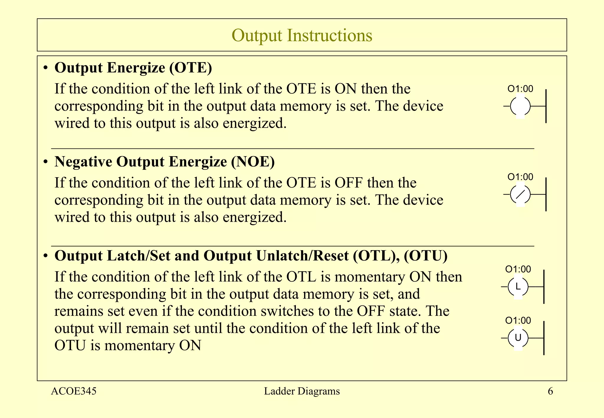
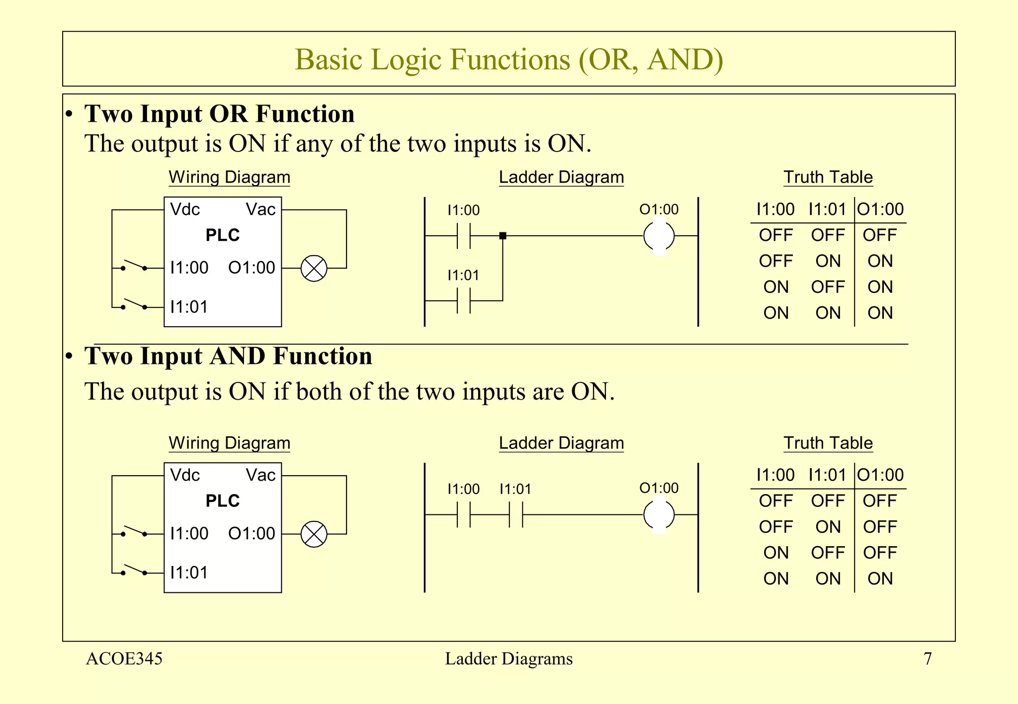
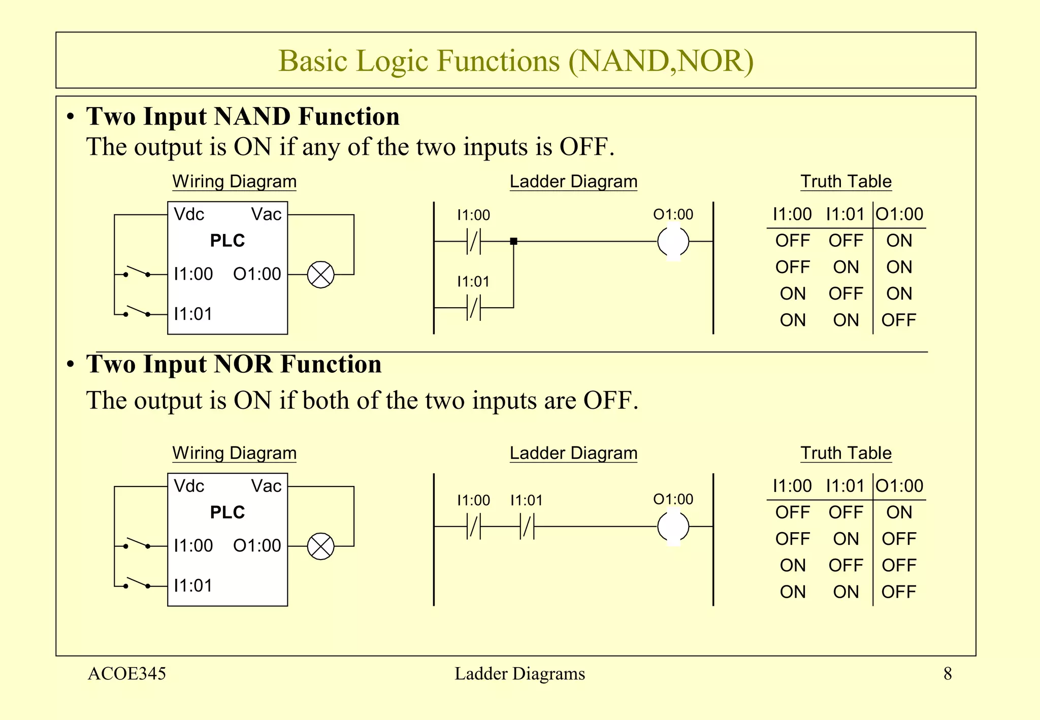
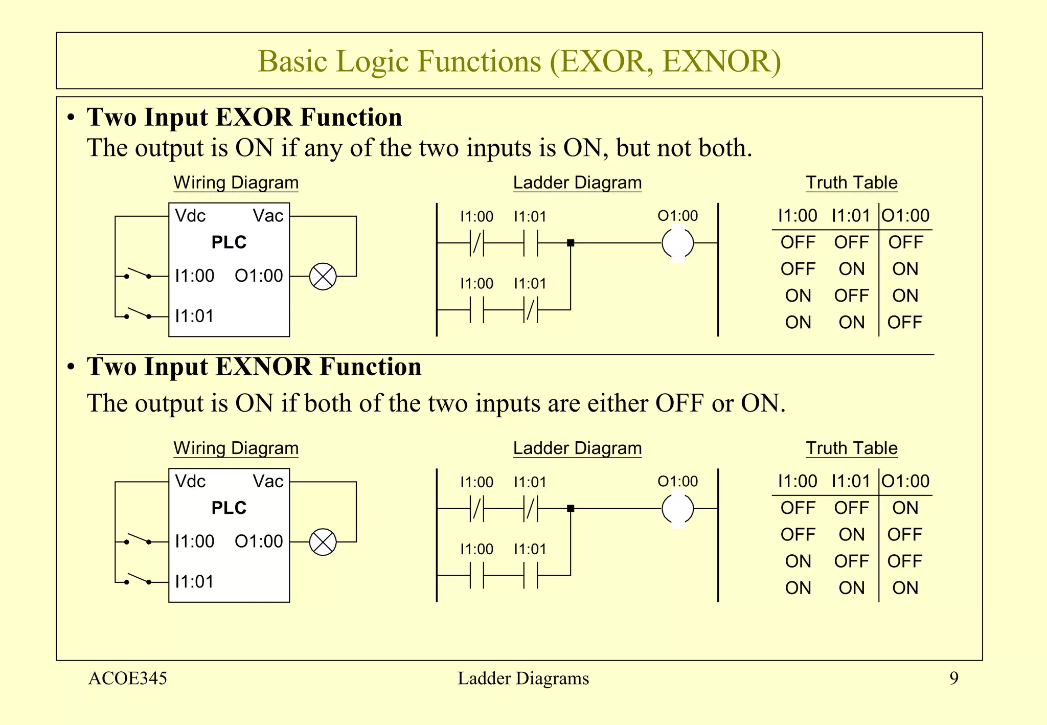
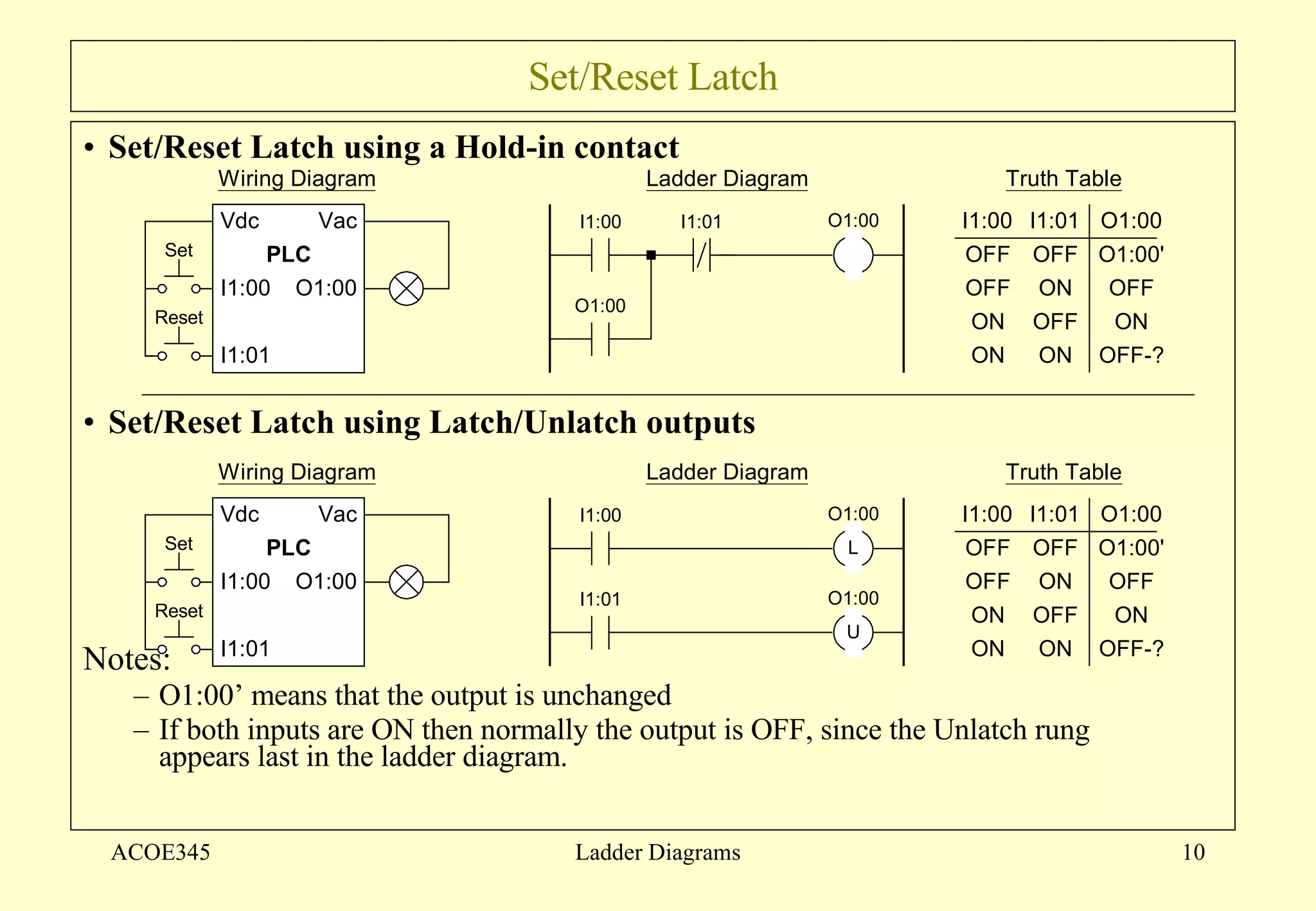
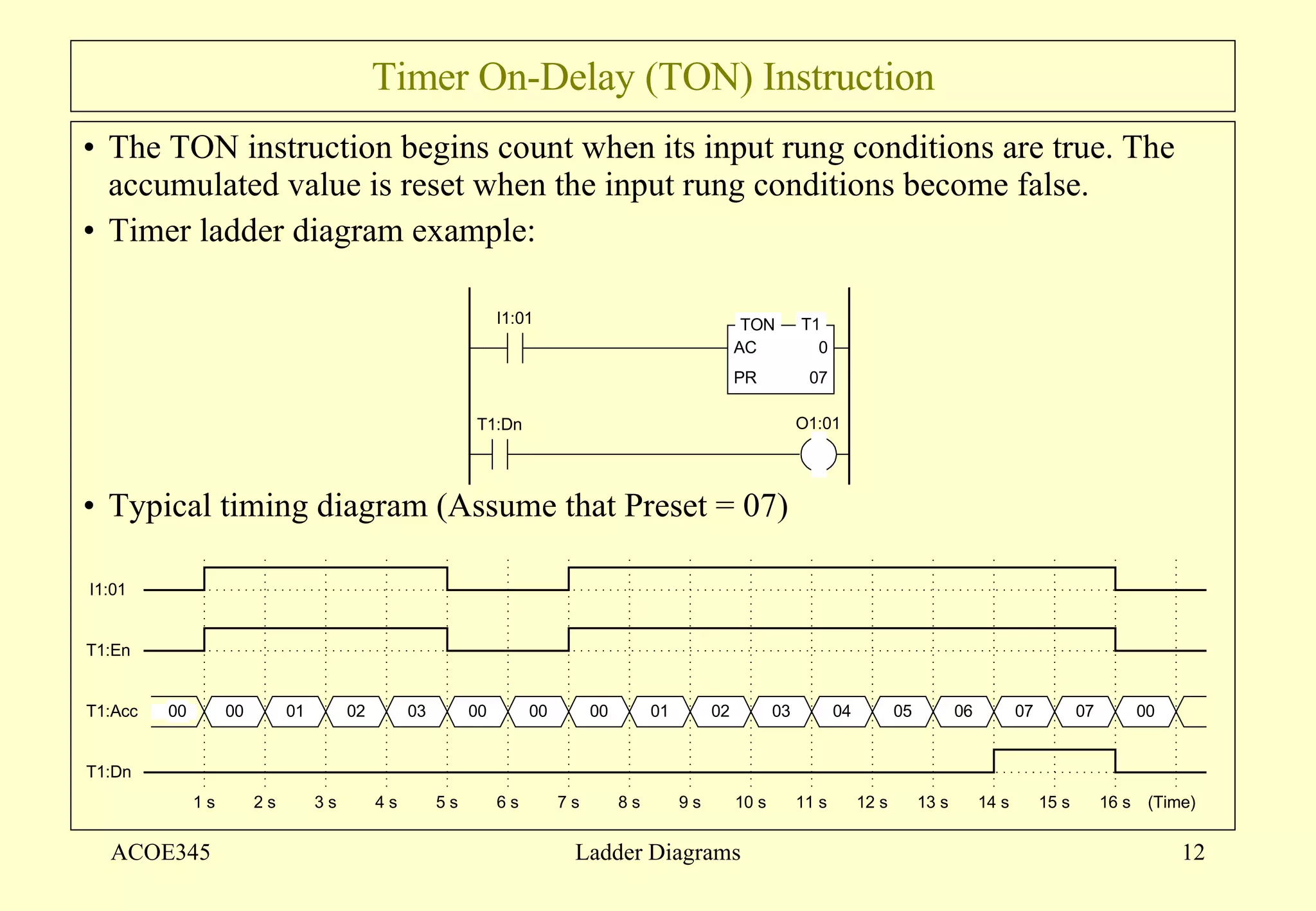
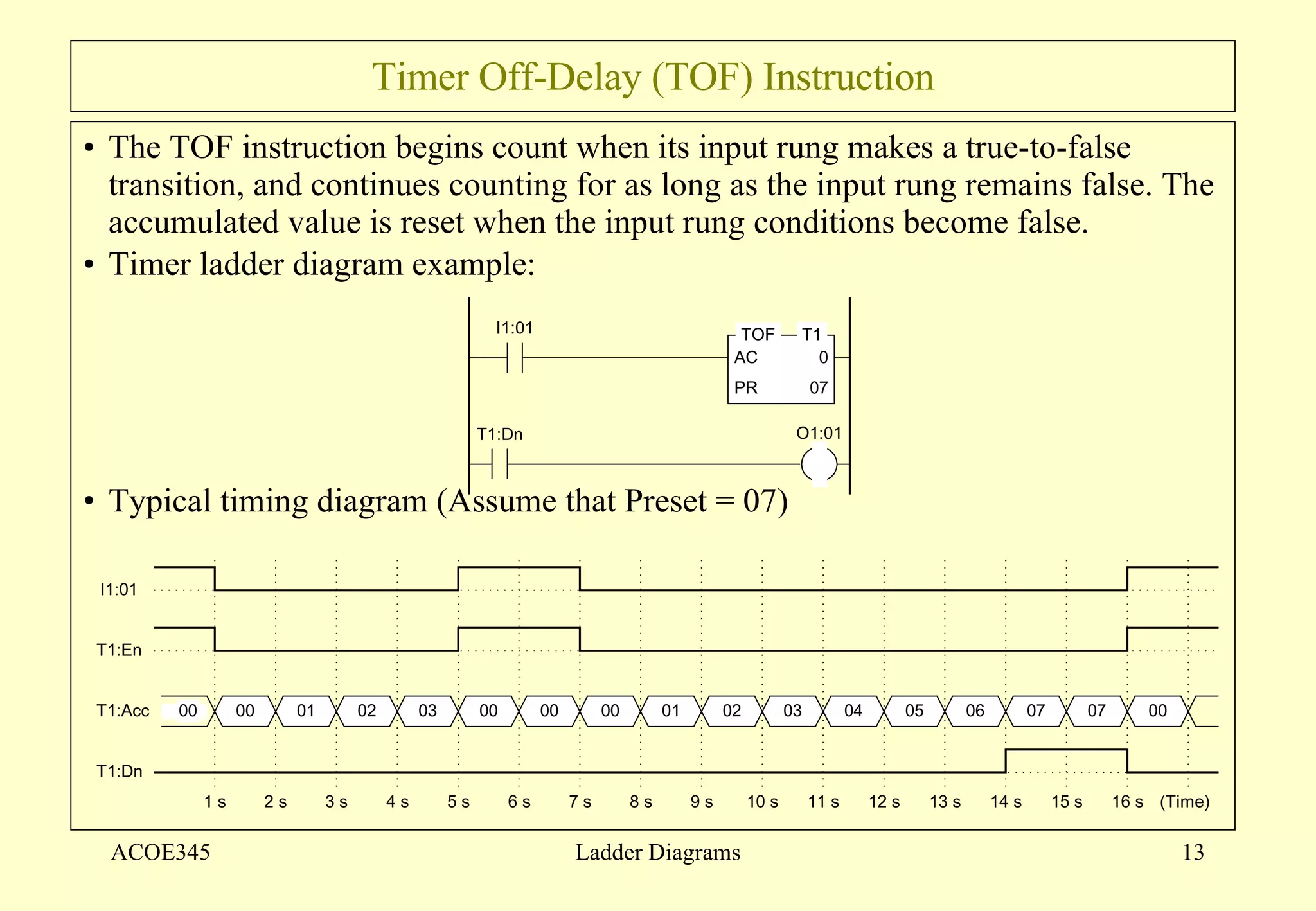
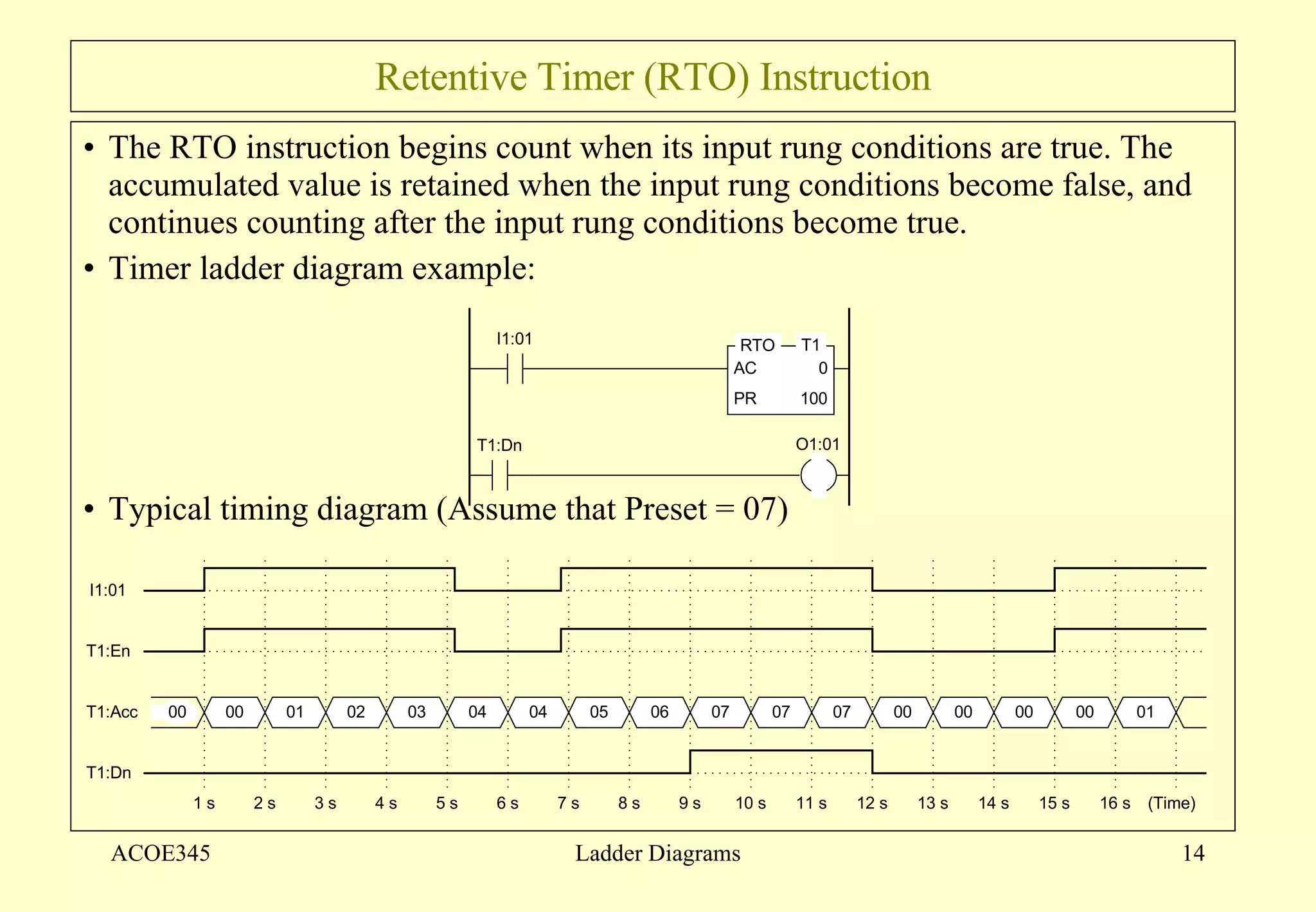

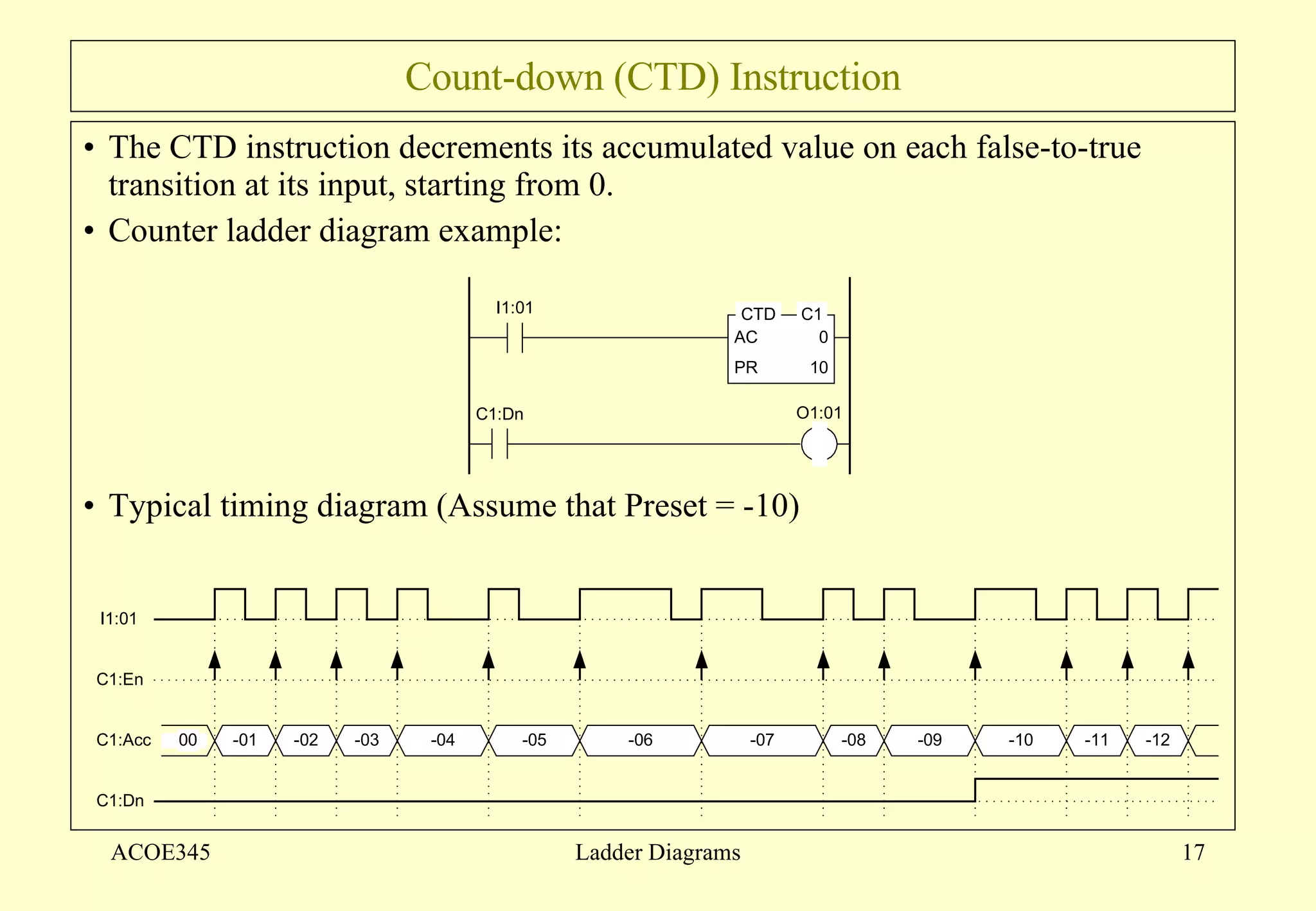
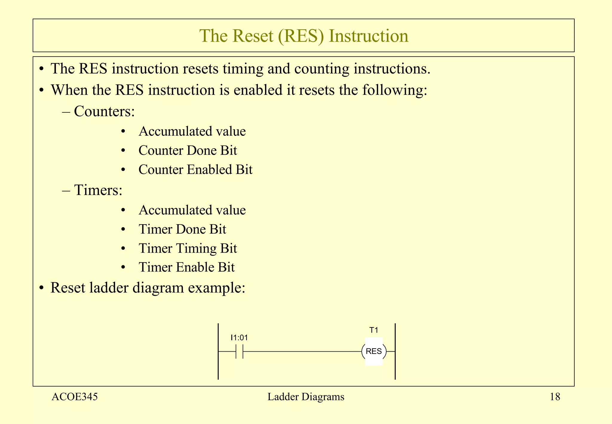

The document introduces ladder diagrams and their basic components and logic. Ladder diagrams are a graphical programming language used to program programmable logic controllers (PLCs). Each rung represents a program statement with inputs on the left and outputs on the right. The PLC executes the ladder diagram by reading input states and determining output states from top to bottom. The document also describes common logic components like contacts, coils, timers, and counters used in ladder diagrams.