SlideShare a Scribd company logo
1 of 8
Download to read offline
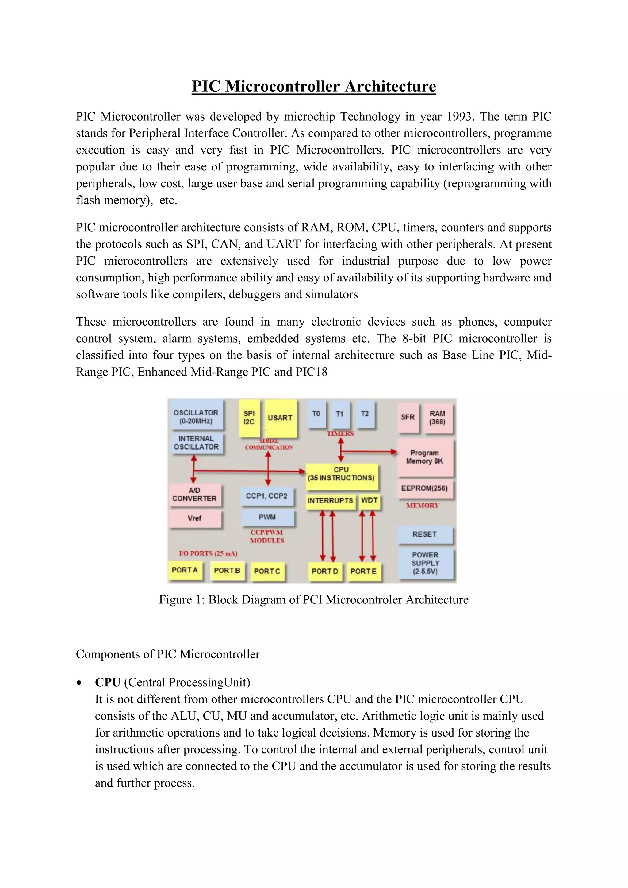
PIC Microcontroller Architecture
PIC Microcontroller was developed by microchip Technology in year 1993. The term PIC
stands for Peripheral Interface Controller. As compared to other microcontrollers, programme
execution is easy and very fast in PIC Microcontrollers. PIC microcontrollers are very
popular due to their ease of programming, wide availability, easy to interfacing with other
peripherals, low cost, large user base and serial programming capability (reprogramming with
flash memory), etc.
PIC microcontroller architecture consists of RAM, ROM, CPU, timers, counters and supports
the protocols such as SPI, CAN, and UART for interfacing with other peripherals. At present
PIC microcontrollers are extensively used for industrial purpose due to low power
consumption, high performance ability and easy of availability of its supporting hardware and
software tools like compilers, debuggers and simulators
These microcontrollers are found in many electronic devices such as phones, computer
control system, alarm systems, embedded systems etc. The 8-bit PIC microcontroller is
classified into four types on the basis of internal architecture such as Base Line PIC, Mid-
Range PIC, Enhanced Mid-Range PIC and PIC18
Figure 1: Block Diagram of PCI Microcontroler Architecture
Components of PIC Microcontroller
 CPU (Central ProcessingUnit)
It is not different from other microcontrollers CPU and the PIC microcontroller CPU
consists of the ALU, CU, MU and accumulator, etc. Arithmetic logic unit is mainly used
for arithmetic operations and to take logical decisions. Memory is used for storing the
instructions after processing. To control the internal and external peripherals, control unit
is used which are connected to the CPU and the accumulator is used for storing the results
and further process.
 Memory Organization:
Programme Memory: It contains the written program after we burned it in
microcontroller. Program Counter executes commands stored in the program memory,
one after the other. Pic microcontroller can have 8K words x 14 bits of Flash program
memory that can be electrically erased and reprogrammed. Whenever we burn program
into the micro, we erase an old program and write a new one.
Data Memory:
It is a RAM type which is used to store the data temporarily in its registers. The RAM
memory is classified into banks. Each bank extends up to 7Fh (128 bytes). Number of
banks may vary depending on the microcontroller. PIC16F84 has only two banks. Banks
contain Special Function Registers (SFR) and General Purpose Registers (GPR). The
lower locations of each bank are reserved for the Special Function Registers and upper
locations are for General Purpose Registers.
Figure 2: Memory Organization of PIC Microcontroller
The memory module in the PIC Microcontroller architecture consists of random Access
Memory (RAM), Read Only Memory (ROM), and Stack
Random Access Memory (RAM): RAM is an unstable memory which is used to store the
data temporarily in its registers. The RAM memory is classified into two banks, and each
bank consists of so many registers. The RAM registers are classified into two types:
o Special Function Registers (SFR): These registers are used for special purposes
only as the name SFR implies. These registers will perform according to the
functions assigned to them , and they cannot be used as normal registers. For
example, if you cannot use the STATUS register for storing the data, these
registers are used for showing the operation or status of the program. So, user
cannot change the function of the SFR; the function is given by the retailer at the
time of manufacturing. Three important SFRs for programming are:
 STATUS register : It changes the bank
 PORT registers : It assigns logic values 0 or 1 to the ports
 TRIS registers : It is a data direction register for input and output
o General Purpose Registers (GPR): These registers are used for general purpose
only as the name implies. For example, if we want to multiply two numbers by
using the PIC microcontroller. Generally, we use registers for multiplying and
storing the numbers in other registers. So these registers don’t have any special
function,- CPU can easily access the data in the registers.
Read Only Memory (ROM): Read only memory is a stable memory which is used to store the
data permanently. In PIC microcontroller architecture, the architecture ROM stores the
instructions or program, according to the program the microcontroller acts. The ROM is also
called as program memory, wherein the user will write the program for microcontroller and
saves it permanently, and finally the program is executed by the CPU. The microcontroller
performance depends on the instruction, which is executed by the CPU.
o Electrically Erasable Programmable Read Only Memory (EEPROM): In the normal
ROM, we can write the program for only once we cannot use again the
microcontroller for multiple times. But, in the EEPROM, we can program the ROM
multiple times.
o Flash Memory: Flash memory is also programmable read only memory (PROM) in
which we can read, write and erase the program thousands of times. Generally, the
PIC microcontroller uses this type of ROM.
Stack: When an interrupt occurs, first the PIC microcontroller has to execute the interrupt and
the existing process address. Then that is being executed is stored in the stack. After
completing the execution of the interrupt, the microcontroller calls the process with the help
of address, which is stored in the stack and get executes the process.
 I/O Ports (Port A, Port B, Port C, Port D, & Port E)
Let us take PIC16 series, it consists of five ports, such as Port A, Port B, Port C, Port D
and Port E.
Port A: This port is 7-bit wide and can be used for both input and output. The status of
TRISA register decided whether it is used as input or output port.
Port B: It is an 8-bit port. This port also can be used as input and output. Moreover in
input mode four of its bits are variable according to the interrupt signals.
Port C: It is also an 8-bit port and can be used as both input and output port which is
determined by the status of the TRISC register.
Port D: This 8-bit port, unlike Port A, B and C is not an input/output port, but is used as
acts as a slave port for the connection to the microprocessor When in I/O mode Port D all
pins should have Schmitt Trigger buffers.
Port E: It is a 3-bit port which is used as the additional feature of the control signals to the
A/D converter
 BUS: BUS is used to transfer and receive the data from one peripheral to another. It is
classified into two types such as data bus and address.
Data Bus: It is used for only transfer or receive the data.
Address Bus: Address bus is used to transmit the memory address from the peripherals to the
CPU. I/O pins are used to interface the external peripherals; UART and USART both are
serial communication protocols which are used for interfacing serial devices like GSM, GPS,
Bluetooth, IR , etc.
Figure 3: Bus
 A/D & D/A Converters: The main intention of this analog to digital converter is to
convert analog voltage values to digital voltage values. A/D module of PIC
microcontroller consists of 5 inputs for 28 pin devices and 8 inputs for 40 pin devices.
The operation of the analog to digital converter is controlled by ADCON0 and ADCON1
special registers. The upper bits of the converter are stored in register ADRESH and
lower bits of the converter are stored in register ADRESL. For this operation, it requires
5V of an analog reference voltage.
Figure 4: A/D converter System
There are no analog outputs in PIC Microcontroller. To get analog output we have to use
external Digital-to-Analog Converter (DAC). It can convert 8 bits of digital number from
the eight digital outputs of PIC microcontroller.
 Timers/Counters: Timers and counters are important as timers can tell the time and
count. PIC microcontroller can have up to four timers (depending upon the family)
Timer0, Timer1, Timer2 and Timer3. Timer0 and Timer2 are of 8-bits while the Timer1
and Timer3 are of 16-bits, which can also be used as a counter. These timers work
according to the selected modes.
 Interrupts: PIC microcontroller consists of 20 internal interrupts and three external
interrupt sources which are associated with different peripherals like ADC, USART,
Timers, and so on.
 Serial Communications: Serial communication is the method of transferring data one bit
at a time sequentially over a communication channel.
o USART: The name USART stands for Universal synchronous and Asynchronous
Receiver and Transmitter which is a serial communication for two protocols. It is used
for transmitting and receiving the data bit by bit over a single wire with respect to
clock pulses. The PIC microcontroller has two pins TXD and RXD. These pins are
used for transmitting and receiving the data serially.
o SPI Protocol: The term SPI stands for Serial Peripheral Interface. This protocol is
used to send data between PIC microcontroller and other peripherals such as SD
cards, sensors and shift registers. PIC microcontroller support three wire SPI
communications between two devices on a common clock source. The data rate of
SPI protocol is more than that of the USART.
o I2C Protocol: The term I2C stands for Inter Integrated Circuit, and it is a serial
protocol which is used to connect low speed devices such as EEPROMS,
microcontrollers, A/D converters, etc. PIC microcontroller support two wires
Interface or I2C communication between two devices which can work as both Master
and Slave device.
 Oscillators: Oscillators are used for timing generation. Pic microcontrollers consist of
external oscillators like RC oscillators or crystal oscillators. Where the crystal oscillator is
connected between the two oscillator pins. The value of the capacitor is connected to
every pin that decides the mode of the operation of the oscillator. The modes are crystal
mode, high-speed mode and the low-power mode. In case of RC oscillators, the value of
the resistor & capacitor determine the clock frequency and the range of clock frequency is
30KHz to 4MHz.
 CCP Module: The name CCP module stands for capture/compare/PWM where it
works in three modes such as capture mode, compare mode and PWM mode.
o Capture Mode: Capture mode captures the time of arrival of a signal, or in other
words, when the CCP pin goes high, it captures the value of the Timer1.
o Compare Mode: Compare mode acts as an analog comparator. When the timer1 value
reaches a certain reference value, then it generates an output.
o PWM Mode: PWM mode provides pulse width modulated output with a 10-bit
resolution and programmable duty cycle.
PIN Diagram of PIC microcontroller and its explanation
Figure 5: PIN Diagram of PIC Microcontroller
Table1: Pin Description of PIC Microcontroller
Pin Number Pin Name Description
1. MCLR̅̅̅̅̅̅̅̅/VPP
MCLR is used during programming, mostly connected to
programmer like PicKit
2. RA0/AN0 Analog pin 0 or 0th
pin of PORTA
3. RA1/AN1 Analog pin 1 or 1st
pin of PORTA
4. RA2/AN2/Vref- Analog pin 2 or 2nd
pin of PORTA
5. RA3/AN3/Vref+ Analog pin 3 or 3rd
pin of PORTA
6. RA4/T0CKI/C1out 4th
pin of PORTA
7. RA5/AN4/SS/C2out Analog pin 4 or 5th
pin of PORTA
8. RE0/RD/AN5 Analog pin 5 or 0th
pin of PORTE
9. RE1/WR/AN6 Analog pin 6 or 1st
pin of PORTE
10. RE2/CS/AN7 7th
pin of PORTE
11. Vdd Ground pin of MCU
12. Vss Positive pin of MCU (+5V)
13. OSC1/CLKI External Oscillator/clock input pin
14. OSC2/CLKO External Oscillator/clock output pin
15. RC0/T1OSO/T1CKI 0th
pin of PORT C
16. RC1/T1OSI/CCP2 1st
pin of PORTC or Timer/PWM pin
17. RC2/CCP1 2nd
pin of PORTC or Timer/PWM pin
18. RC3/SCK/SCL 3rd
pin of PORTC
19. RD0/PSP0 0th
pin of PORTD
20. RD1/PSPI 1st
pin of PORTD
21. RD2/PSP2 2nd
pin of PORTD
22. RD3/PSP3 3rd
pin of PORTD
23. RC4/SDI/SDA 4th
pin of PORTC or Serial Data in pin
24. RC5/SDO 5th
pin of PORTC or Serial Data Out pin
25. RC6/Tx/CK 6th
pin of PORTC or Transmitter pin of Microcontroller
26. RC7/Rx/DT 7th
pin of PORTC or Receiver pin of Microcontroller
27. RD4/PSP4 4th
pin of PORTD
28. RD5/PSP5 5th
pin of PORTD
29. RD6/PSP6 6th
pin of PORTD
30. RD7/PSP7 7th
pin of PORTD
31. Vss Positive pin of MCU (+5V)
32. Vdd Ground pin of MCU
33. RB0/INT 0th
pin of PORTB or External Interrupt pin
34. RB1 1st
pin of PORTB
35. RB2 2nd
pin of PORTB
36. RB3/PGM 3rd
pin of PORTB or connected to programmer
37. RB4 4th
pin of PORTB
38. RB5 5th
pin of PORTB
39. RB6/PGC 6th
pin of PORTB or connected to programmer
40. RB7/PGD 7th
pin of PORTB or connected to programmer
References
1. https://www.watelectronics.com/pic-microcontroller-architecture-and-applications/
2. https://www.electronicshub.org/pic-microcontroller-architecture/
3. https://www.elprocus.com/introduction-to-pic-microcontrollers-and-its-architecture/
4. https://microcontrollerslab.com/pic-microcontroller-architecture/
5. https://components101.com/pic16f877a-pin-diagram-description-features-datasheet

More Related Content

What's hot

8051 microcontroller
8051 microcontroller 8051 microcontroller
8051 microcontroller Gaurav Verma
 
Introduction to ARM LPC2148
Introduction to ARM LPC2148Introduction to ARM LPC2148
Introduction to ARM LPC2148Veera Kumar
 
Introduction to arm processor
Introduction to arm processorIntroduction to arm processor
Introduction to arm processorRAMPRAKASHT1
 
Memory & I/O interfacing
Memory & I/O  interfacingMemory & I/O  interfacing
Memory & I/O interfacingdeval patel
 
8051 Addressing Modes
8051 Addressing Modes8051 Addressing Modes
8051 Addressing ModesSenthil Kumar
 
Microcontroller pic 16f877 addressing modes instructions and programming
Microcontroller pic 16f877 addressing modes instructions and programmingMicrocontroller pic 16f877 addressing modes instructions and programming
Microcontroller pic 16f877 addressing modes instructions and programmingNilesh Bhaskarrao Bahadure
 
Interfacing with peripherals: analog to digital converters and digital to ana...
Interfacing with peripherals: analog to digital converters and digital to ana...Interfacing with peripherals: analog to digital converters and digital to ana...
Interfacing with peripherals: analog to digital converters and digital to ana...NimeshSingh27
 
8051 Microcontroller ppt
8051 Microcontroller ppt8051 Microcontroller ppt
8051 Microcontroller pptRahul Kumar
 
Arm architecture
Arm architectureArm architecture
Arm architectureMinYeop Na
 
Architecture of 8051
Architecture of 8051Architecture of 8051
Architecture of 8051hello_priti
 
PIC16F877A interfacing with LCD
PIC16F877A interfacing with LCDPIC16F877A interfacing with LCD
PIC16F877A interfacing with LCDsunil polo
 
Lect 2 ARM processor architecture
Lect 2 ARM processor architectureLect 2 ARM processor architecture
Lect 2 ARM processor architectureDr.YNM
 
8051 microcontroller and embedded system
8051 microcontroller and embedded system8051 microcontroller and embedded system
8051 microcontroller and embedded systemsb108ec
 
MICROCONTROLLER 8051- Architecture & Pin Configuration
MICROCONTROLLER 8051- Architecture & Pin Configuration MICROCONTROLLER 8051- Architecture & Pin Configuration
MICROCONTROLLER 8051- Architecture & Pin Configuration AKHIL MADANKAR
 

What's hot (20)

Embedded c
Embedded cEmbedded c
Embedded c
 
8051 microcontroller
8051 microcontroller 8051 microcontroller
8051 microcontroller
 
Introduction to ARM LPC2148
Introduction to ARM LPC2148Introduction to ARM LPC2148
Introduction to ARM LPC2148
 
Serial Communication in 8051
Serial Communication in 8051Serial Communication in 8051
Serial Communication in 8051
 
Introduction to arm processor
Introduction to arm processorIntroduction to arm processor
Introduction to arm processor
 
ARM- Programmer's Model
ARM- Programmer's ModelARM- Programmer's Model
ARM- Programmer's Model
 
ARM Processor
ARM ProcessorARM Processor
ARM Processor
 
Memory & I/O interfacing
Memory & I/O  interfacingMemory & I/O  interfacing
Memory & I/O interfacing
 
8051 Addressing Modes
8051 Addressing Modes8051 Addressing Modes
8051 Addressing Modes
 
ARM Architecture
ARM ArchitectureARM Architecture
ARM Architecture
 
Microcontroller pic 16f877 addressing modes instructions and programming
Microcontroller pic 16f877 addressing modes instructions and programmingMicrocontroller pic 16f877 addressing modes instructions and programming
Microcontroller pic 16f877 addressing modes instructions and programming
 
Interfacing with peripherals: analog to digital converters and digital to ana...
Interfacing with peripherals: analog to digital converters and digital to ana...Interfacing with peripherals: analog to digital converters and digital to ana...
Interfacing with peripherals: analog to digital converters and digital to ana...
 
8051 Microcontroller ppt
8051 Microcontroller ppt8051 Microcontroller ppt
8051 Microcontroller ppt
 
Arm architecture
Arm architectureArm architecture
Arm architecture
 
Architecture of 8051
Architecture of 8051Architecture of 8051
Architecture of 8051
 
PIC16F877A interfacing with LCD
PIC16F877A interfacing with LCDPIC16F877A interfacing with LCD
PIC16F877A interfacing with LCD
 
Lect 2 ARM processor architecture
Lect 2 ARM processor architectureLect 2 ARM processor architecture
Lect 2 ARM processor architecture
 
8051 microcontroller and embedded system
8051 microcontroller and embedded system8051 microcontroller and embedded system
8051 microcontroller and embedded system
 
MICROCONTROLLER 8051- Architecture & Pin Configuration
MICROCONTROLLER 8051- Architecture & Pin Configuration MICROCONTROLLER 8051- Architecture & Pin Configuration
MICROCONTROLLER 8051- Architecture & Pin Configuration
 
UART
UARTUART
UART
 

Similar to Pic microcontroller architecture

UNIT-V (PIC16F877-Microcontrollers).pdf
UNIT-V (PIC16F877-Microcontrollers).pdfUNIT-V (PIC16F877-Microcontrollers).pdf
UNIT-V (PIC16F877-Microcontrollers).pdfdhiyasrinivasan112
 
Overview of Microcontroller and ATMega32 microcontroller
Overview of Microcontroller and ATMega32 microcontrollerOverview of Microcontroller and ATMega32 microcontroller
Overview of Microcontroller and ATMega32 microcontrollerRup Chowdhury
 
AN INTEGRATED FOUR-PORT DC-DC CONVERTER-CEI0080
AN INTEGRATED FOUR-PORT DC-DC CONVERTER-CEI0080AN INTEGRATED FOUR-PORT DC-DC CONVERTER-CEI0080
AN INTEGRATED FOUR-PORT DC-DC CONVERTER-CEI0080Vivek Venugopal
 
Chp4 introduction to the pic microcontroller copy
Chp4 introduction to the pic microcontroller   copyChp4 introduction to the pic microcontroller   copy
Chp4 introduction to the pic microcontroller copymkazree
 
SYBSC IT SEM IV EMBEDDED SYSTEMS UNIT III The 8051 Microcontrollers
SYBSC IT SEM IV EMBEDDED SYSTEMS UNIT III  The 8051 MicrocontrollersSYBSC IT SEM IV EMBEDDED SYSTEMS UNIT III  The 8051 Microcontrollers
SYBSC IT SEM IV EMBEDDED SYSTEMS UNIT III The 8051 MicrocontrollersArti Parab Academics
 
embedded system and microcontroller
 embedded system and microcontroller embedded system and microcontroller
embedded system and microcontrollerSHILPA Sillobhargav
 
EE6008 MCBSD - Introduction to PIC Micro controller
EE6008 MCBSD - Introduction to PIC Micro controller EE6008 MCBSD - Introduction to PIC Micro controller
EE6008 MCBSD - Introduction to PIC Micro controller pavihari
 
Pic microcontroller [autosaved] [autosaved]
Pic microcontroller [autosaved] [autosaved]Pic microcontroller [autosaved] [autosaved]
Pic microcontroller [autosaved] [autosaved]gauravholani
 
INDUSTRIAL TRAINING REPORT EMBEDDED SYSTEM.pptx
INDUSTRIAL TRAINING REPORT EMBEDDED SYSTEM.pptxINDUSTRIAL TRAINING REPORT EMBEDDED SYSTEM.pptx
INDUSTRIAL TRAINING REPORT EMBEDDED SYSTEM.pptxMeghdeepSingh
 
EMBEDDED SYSTEMS AND IOT lab manual for enginnering students
EMBEDDED SYSTEMS AND IOT lab manual for enginnering studentsEMBEDDED SYSTEMS AND IOT lab manual for enginnering students
EMBEDDED SYSTEMS AND IOT lab manual for enginnering studentseceprinter6
 
Introduction to 8085 Microprocessors
Introduction to 8085 MicroprocessorsIntroduction to 8085 Microprocessors
Introduction to 8085 MicroprocessorsVeerakumar S
 
PIC MICROCONTROLLERS -CLASS NOTES
PIC MICROCONTROLLERS -CLASS NOTESPIC MICROCONTROLLERS -CLASS NOTES
PIC MICROCONTROLLERS -CLASS NOTESDr.YNM
 
Module 5 embedded systems,8051
Module 5 embedded systems,8051Module 5 embedded systems,8051
Module 5 embedded systems,8051Deepak John
 
microprocessor8085 power point presentation
microprocessor8085 power point presentationmicroprocessor8085 power point presentation
microprocessor8085 power point presentationrohitkuarm5667
 

Similar to Pic microcontroller architecture (20)

UNIT-V (PIC16F877-Microcontrollers).pdf
UNIT-V (PIC16F877-Microcontrollers).pdfUNIT-V (PIC16F877-Microcontrollers).pdf
UNIT-V (PIC16F877-Microcontrollers).pdf
 
Overview of Microcontroller and ATMega32 microcontroller
Overview of Microcontroller and ATMega32 microcontrollerOverview of Microcontroller and ATMega32 microcontroller
Overview of Microcontroller and ATMega32 microcontroller
 
AN INTEGRATED FOUR-PORT DC-DC CONVERTER-CEI0080
AN INTEGRATED FOUR-PORT DC-DC CONVERTER-CEI0080AN INTEGRATED FOUR-PORT DC-DC CONVERTER-CEI0080
AN INTEGRATED FOUR-PORT DC-DC CONVERTER-CEI0080
 
Chp4 introduction to the pic microcontroller copy
Chp4 introduction to the pic microcontroller   copyChp4 introduction to the pic microcontroller   copy
Chp4 introduction to the pic microcontroller copy
 
SYBSC IT SEM IV EMBEDDED SYSTEMS UNIT III The 8051 Microcontrollers
SYBSC IT SEM IV EMBEDDED SYSTEMS UNIT III  The 8051 MicrocontrollersSYBSC IT SEM IV EMBEDDED SYSTEMS UNIT III  The 8051 Microcontrollers
SYBSC IT SEM IV EMBEDDED SYSTEMS UNIT III The 8051 Microcontrollers
 
embedded system and microcontroller
 embedded system and microcontroller embedded system and microcontroller
embedded system and microcontroller
 
Ee6008 mcbsd notes
Ee6008 mcbsd notesEe6008 mcbsd notes
Ee6008 mcbsd notes
 
EE6008 MBSD
EE6008  MBSDEE6008  MBSD
EE6008 MBSD
 
EE6008 MCBSD - Introduction to PIC Micro controller
EE6008 MCBSD - Introduction to PIC Micro controller EE6008 MCBSD - Introduction to PIC Micro controller
EE6008 MCBSD - Introduction to PIC Micro controller
 
Pic microcontroller [autosaved] [autosaved]
Pic microcontroller [autosaved] [autosaved]Pic microcontroller [autosaved] [autosaved]
Pic microcontroller [autosaved] [autosaved]
 
INDUSTRIAL TRAINING REPORT EMBEDDED SYSTEM.pptx
INDUSTRIAL TRAINING REPORT EMBEDDED SYSTEM.pptxINDUSTRIAL TRAINING REPORT EMBEDDED SYSTEM.pptx
INDUSTRIAL TRAINING REPORT EMBEDDED SYSTEM.pptx
 
EMBEDDED SYSTEMS AND IOT lab manual for enginnering students
EMBEDDED SYSTEMS AND IOT lab manual for enginnering studentsEMBEDDED SYSTEMS AND IOT lab manual for enginnering students
EMBEDDED SYSTEMS AND IOT lab manual for enginnering students
 
Introduction to 8085 Microprocessors
Introduction to 8085 MicroprocessorsIntroduction to 8085 Microprocessors
Introduction to 8085 Microprocessors
 
Presentation
PresentationPresentation
Presentation
 
89s52 2
89s52 289s52 2
89s52 2
 
PIC MICROCONTROLLERS -CLASS NOTES
PIC MICROCONTROLLERS -CLASS NOTESPIC MICROCONTROLLERS -CLASS NOTES
PIC MICROCONTROLLERS -CLASS NOTES
 
002079
002079002079
002079
 
Module 5 embedded systems,8051
Module 5 embedded systems,8051Module 5 embedded systems,8051
Module 5 embedded systems,8051
 
microprocessor8085 power point presentation
microprocessor8085 power point presentationmicroprocessor8085 power point presentation
microprocessor8085 power point presentation
 
Pic full note
Pic full notePic full note
Pic full note
 

More from Jamia Hamdard

More from Jamia Hamdard (8)

Unit v
Unit vUnit v
Unit v
 
Embedded system software
Embedded system softwareEmbedded system software
Embedded system software
 
Wireless sensor network
Wireless sensor networkWireless sensor network
Wireless sensor network
 
Registers
RegistersRegisters
Registers
 
Programming
ProgrammingProgramming
Programming
 
Interrupts
InterruptsInterrupts
Interrupts
 
Instructions
InstructionsInstructions
Instructions
 
Introduction to vlsi design
Introduction to vlsi designIntroduction to vlsi design
Introduction to vlsi design
 

Recently uploaded

Arduino_CSE ece ppt for working and principal of arduino.ppt
Arduino_CSE ece ppt for working and principal of arduino.pptArduino_CSE ece ppt for working and principal of arduino.ppt
Arduino_CSE ece ppt for working and principal of arduino.pptSAURABHKUMAR892774
 
Study on Air-Water & Water-Water Heat Exchange in a Finned Tube Exchanger
Study on Air-Water & Water-Water Heat Exchange in a Finned Tube ExchangerStudy on Air-Water & Water-Water Heat Exchange in a Finned Tube Exchanger
Study on Air-Water & Water-Water Heat Exchange in a Finned Tube ExchangerAnamika Sarkar
 
Software and Systems Engineering Standards: Verification and Validation of Sy...
Software and Systems Engineering Standards: Verification and Validation of Sy...Software and Systems Engineering Standards: Verification and Validation of Sy...
Software and Systems Engineering Standards: Verification and Validation of Sy...VICTOR MAESTRE RAMIREZ
 
pipeline in computer architecture design
pipeline in computer architecture  designpipeline in computer architecture  design
pipeline in computer architecture designssuser87fa0c1
 
INFLUENCE OF NANOSILICA ON THE PROPERTIES OF CONCRETE
INFLUENCE OF NANOSILICA ON THE PROPERTIES OF CONCRETEINFLUENCE OF NANOSILICA ON THE PROPERTIES OF CONCRETE
INFLUENCE OF NANOSILICA ON THE PROPERTIES OF CONCRETEroselinkalist12
 
main PPT.pptx of girls hostel security using rfid
main PPT.pptx of girls hostel security using rfidmain PPT.pptx of girls hostel security using rfid
main PPT.pptx of girls hostel security using rfidNikhilNagaraju
 
Work Experience-Dalton Park.pptxfvvvvvvv
Work Experience-Dalton Park.pptxfvvvvvvvWork Experience-Dalton Park.pptxfvvvvvvv
Work Experience-Dalton Park.pptxfvvvvvvvLewisJB
 
Introduction-To-Agricultural-Surveillance-Rover.pptx
Introduction-To-Agricultural-Surveillance-Rover.pptxIntroduction-To-Agricultural-Surveillance-Rover.pptx
Introduction-To-Agricultural-Surveillance-Rover.pptxk795866
 
CCS355 Neural Network & Deep Learning UNIT III notes and Question bank .pdf
CCS355 Neural Network & Deep Learning UNIT III notes and Question bank .pdfCCS355 Neural Network & Deep Learning UNIT III notes and Question bank .pdf
CCS355 Neural Network & Deep Learning UNIT III notes and Question bank .pdfAsst.prof M.Gokilavani
 
Churning of Butter, Factors affecting .
Churning of Butter, Factors affecting  .Churning of Butter, Factors affecting  .
Churning of Butter, Factors affecting .Satyam Kumar
 
CCS355 Neural Network & Deep Learning Unit II Notes with Question bank .pdf
CCS355 Neural Network & Deep Learning Unit II Notes with Question bank .pdfCCS355 Neural Network & Deep Learning Unit II Notes with Question bank .pdf
CCS355 Neural Network & Deep Learning Unit II Notes with Question bank .pdfAsst.prof M.Gokilavani
 
complete construction, environmental and economics information of biomass com...
complete construction, environmental and economics information of biomass com...complete construction, environmental and economics information of biomass com...
complete construction, environmental and economics information of biomass com...asadnawaz62
 
Oxy acetylene welding presentation note.
Oxy acetylene welding presentation note.Oxy acetylene welding presentation note.
Oxy acetylene welding presentation note.eptoze12
 
Gfe Mayur Vihar Call Girls Service WhatsApp -> 9999965857 Available 24x7 ^ De...
Gfe Mayur Vihar Call Girls Service WhatsApp -> 9999965857 Available 24x7 ^ De...Gfe Mayur Vihar Call Girls Service WhatsApp -> 9999965857 Available 24x7 ^ De...
Gfe Mayur Vihar Call Girls Service WhatsApp -> 9999965857 Available 24x7 ^ De...srsj9000
 
DATA ANALYTICS PPT definition usage example
DATA ANALYTICS PPT definition usage exampleDATA ANALYTICS PPT definition usage example
DATA ANALYTICS PPT definition usage examplePragyanshuParadkar1
 
CCS355 Neural Networks & Deep Learning Unit 1 PDF notes with Question bank .pdf
CCS355 Neural Networks & Deep Learning Unit 1 PDF notes with Question bank .pdfCCS355 Neural Networks & Deep Learning Unit 1 PDF notes with Question bank .pdf
CCS355 Neural Networks & Deep Learning Unit 1 PDF notes with Question bank .pdfAsst.prof M.Gokilavani
 
Gurgaon ✡️9711147426✨Call In girls Gurgaon Sector 51 escort service
Gurgaon ✡️9711147426✨Call In girls Gurgaon Sector 51 escort serviceGurgaon ✡️9711147426✨Call In girls Gurgaon Sector 51 escort service
Gurgaon ✡️9711147426✨Call In girls Gurgaon Sector 51 escort servicejennyeacort
 
Biology for Computer Engineers Course Handout.pptx
Biology for Computer Engineers Course Handout.pptxBiology for Computer Engineers Course Handout.pptx
Biology for Computer Engineers Course Handout.pptxDeepakSakkari2
 

Recently uploaded (20)

Arduino_CSE ece ppt for working and principal of arduino.ppt
Arduino_CSE ece ppt for working and principal of arduino.pptArduino_CSE ece ppt for working and principal of arduino.ppt
Arduino_CSE ece ppt for working and principal of arduino.ppt
 
young call girls in Green Park🔝 9953056974 🔝 escort Service
young call girls in Green Park🔝 9953056974 🔝 escort Serviceyoung call girls in Green Park🔝 9953056974 🔝 escort Service
young call girls in Green Park🔝 9953056974 🔝 escort Service
 
Study on Air-Water & Water-Water Heat Exchange in a Finned Tube Exchanger
Study on Air-Water & Water-Water Heat Exchange in a Finned Tube ExchangerStudy on Air-Water & Water-Water Heat Exchange in a Finned Tube Exchanger
Study on Air-Water & Water-Water Heat Exchange in a Finned Tube Exchanger
 
Software and Systems Engineering Standards: Verification and Validation of Sy...
Software and Systems Engineering Standards: Verification and Validation of Sy...Software and Systems Engineering Standards: Verification and Validation of Sy...
Software and Systems Engineering Standards: Verification and Validation of Sy...
 
pipeline in computer architecture design
pipeline in computer architecture  designpipeline in computer architecture  design
pipeline in computer architecture design
 
INFLUENCE OF NANOSILICA ON THE PROPERTIES OF CONCRETE
INFLUENCE OF NANOSILICA ON THE PROPERTIES OF CONCRETEINFLUENCE OF NANOSILICA ON THE PROPERTIES OF CONCRETE
INFLUENCE OF NANOSILICA ON THE PROPERTIES OF CONCRETE
 
main PPT.pptx of girls hostel security using rfid
main PPT.pptx of girls hostel security using rfidmain PPT.pptx of girls hostel security using rfid
main PPT.pptx of girls hostel security using rfid
 
Work Experience-Dalton Park.pptxfvvvvvvv
Work Experience-Dalton Park.pptxfvvvvvvvWork Experience-Dalton Park.pptxfvvvvvvv
Work Experience-Dalton Park.pptxfvvvvvvv
 
Introduction-To-Agricultural-Surveillance-Rover.pptx
Introduction-To-Agricultural-Surveillance-Rover.pptxIntroduction-To-Agricultural-Surveillance-Rover.pptx
Introduction-To-Agricultural-Surveillance-Rover.pptx
 
CCS355 Neural Network & Deep Learning UNIT III notes and Question bank .pdf
CCS355 Neural Network & Deep Learning UNIT III notes and Question bank .pdfCCS355 Neural Network & Deep Learning UNIT III notes and Question bank .pdf
CCS355 Neural Network & Deep Learning UNIT III notes and Question bank .pdf
 
Churning of Butter, Factors affecting .
Churning of Butter, Factors affecting  .Churning of Butter, Factors affecting  .
Churning of Butter, Factors affecting .
 
CCS355 Neural Network & Deep Learning Unit II Notes with Question bank .pdf
CCS355 Neural Network & Deep Learning Unit II Notes with Question bank .pdfCCS355 Neural Network & Deep Learning Unit II Notes with Question bank .pdf
CCS355 Neural Network & Deep Learning Unit II Notes with Question bank .pdf
 
complete construction, environmental and economics information of biomass com...
complete construction, environmental and economics information of biomass com...complete construction, environmental and economics information of biomass com...
complete construction, environmental and economics information of biomass com...
 
Oxy acetylene welding presentation note.
Oxy acetylene welding presentation note.Oxy acetylene welding presentation note.
Oxy acetylene welding presentation note.
 
Gfe Mayur Vihar Call Girls Service WhatsApp -> 9999965857 Available 24x7 ^ De...
Gfe Mayur Vihar Call Girls Service WhatsApp -> 9999965857 Available 24x7 ^ De...Gfe Mayur Vihar Call Girls Service WhatsApp -> 9999965857 Available 24x7 ^ De...
Gfe Mayur Vihar Call Girls Service WhatsApp -> 9999965857 Available 24x7 ^ De...
 
young call girls in Rajiv Chowk🔝 9953056974 🔝 Delhi escort Service
young call girls in Rajiv Chowk🔝 9953056974 🔝 Delhi escort Serviceyoung call girls in Rajiv Chowk🔝 9953056974 🔝 Delhi escort Service
young call girls in Rajiv Chowk🔝 9953056974 🔝 Delhi escort Service
 
DATA ANALYTICS PPT definition usage example
DATA ANALYTICS PPT definition usage exampleDATA ANALYTICS PPT definition usage example
DATA ANALYTICS PPT definition usage example
 
CCS355 Neural Networks & Deep Learning Unit 1 PDF notes with Question bank .pdf
CCS355 Neural Networks & Deep Learning Unit 1 PDF notes with Question bank .pdfCCS355 Neural Networks & Deep Learning Unit 1 PDF notes with Question bank .pdf
CCS355 Neural Networks & Deep Learning Unit 1 PDF notes with Question bank .pdf
 
Gurgaon ✡️9711147426✨Call In girls Gurgaon Sector 51 escort service
Gurgaon ✡️9711147426✨Call In girls Gurgaon Sector 51 escort serviceGurgaon ✡️9711147426✨Call In girls Gurgaon Sector 51 escort service
Gurgaon ✡️9711147426✨Call In girls Gurgaon Sector 51 escort service
 
Biology for Computer Engineers Course Handout.pptx
Biology for Computer Engineers Course Handout.pptxBiology for Computer Engineers Course Handout.pptx
Biology for Computer Engineers Course Handout.pptx
 

Pic microcontroller architecture

  • 1. PIC Microcontroller Architecture PIC Microcontroller was developed by microchip Technology in year 1993. The term PIC stands for Peripheral Interface Controller. As compared to other microcontrollers, programme execution is easy and very fast in PIC Microcontrollers. PIC microcontrollers are very popular due to their ease of programming, wide availability, easy to interfacing with other peripherals, low cost, large user base and serial programming capability (reprogramming with flash memory), etc. PIC microcontroller architecture consists of RAM, ROM, CPU, timers, counters and supports the protocols such as SPI, CAN, and UART for interfacing with other peripherals. At present PIC microcontrollers are extensively used for industrial purpose due to low power consumption, high performance ability and easy of availability of its supporting hardware and software tools like compilers, debuggers and simulators These microcontrollers are found in many electronic devices such as phones, computer control system, alarm systems, embedded systems etc. The 8-bit PIC microcontroller is classified into four types on the basis of internal architecture such as Base Line PIC, Mid- Range PIC, Enhanced Mid-Range PIC and PIC18 Figure 1: Block Diagram of PCI Microcontroler Architecture Components of PIC Microcontroller  CPU (Central ProcessingUnit) It is not different from other microcontrollers CPU and the PIC microcontroller CPU consists of the ALU, CU, MU and accumulator, etc. Arithmetic logic unit is mainly used for arithmetic operations and to take logical decisions. Memory is used for storing the instructions after processing. To control the internal and external peripherals, control unit is used which are connected to the CPU and the accumulator is used for storing the results and further process.
  • 2.  Memory Organization: Programme Memory: It contains the written program after we burned it in microcontroller. Program Counter executes commands stored in the program memory, one after the other. Pic microcontroller can have 8K words x 14 bits of Flash program memory that can be electrically erased and reprogrammed. Whenever we burn program into the micro, we erase an old program and write a new one. Data Memory: It is a RAM type which is used to store the data temporarily in its registers. The RAM memory is classified into banks. Each bank extends up to 7Fh (128 bytes). Number of banks may vary depending on the microcontroller. PIC16F84 has only two banks. Banks contain Special Function Registers (SFR) and General Purpose Registers (GPR). The lower locations of each bank are reserved for the Special Function Registers and upper locations are for General Purpose Registers. Figure 2: Memory Organization of PIC Microcontroller The memory module in the PIC Microcontroller architecture consists of random Access Memory (RAM), Read Only Memory (ROM), and Stack Random Access Memory (RAM): RAM is an unstable memory which is used to store the data temporarily in its registers. The RAM memory is classified into two banks, and each bank consists of so many registers. The RAM registers are classified into two types: o Special Function Registers (SFR): These registers are used for special purposes only as the name SFR implies. These registers will perform according to the functions assigned to them , and they cannot be used as normal registers. For example, if you cannot use the STATUS register for storing the data, these registers are used for showing the operation or status of the program. So, user cannot change the function of the SFR; the function is given by the retailer at the time of manufacturing. Three important SFRs for programming are:  STATUS register : It changes the bank  PORT registers : It assigns logic values 0 or 1 to the ports  TRIS registers : It is a data direction register for input and output o General Purpose Registers (GPR): These registers are used for general purpose only as the name implies. For example, if we want to multiply two numbers by
  • 3. using the PIC microcontroller. Generally, we use registers for multiplying and storing the numbers in other registers. So these registers don’t have any special function,- CPU can easily access the data in the registers. Read Only Memory (ROM): Read only memory is a stable memory which is used to store the data permanently. In PIC microcontroller architecture, the architecture ROM stores the instructions or program, according to the program the microcontroller acts. The ROM is also called as program memory, wherein the user will write the program for microcontroller and saves it permanently, and finally the program is executed by the CPU. The microcontroller performance depends on the instruction, which is executed by the CPU. o Electrically Erasable Programmable Read Only Memory (EEPROM): In the normal ROM, we can write the program for only once we cannot use again the microcontroller for multiple times. But, in the EEPROM, we can program the ROM multiple times. o Flash Memory: Flash memory is also programmable read only memory (PROM) in which we can read, write and erase the program thousands of times. Generally, the PIC microcontroller uses this type of ROM. Stack: When an interrupt occurs, first the PIC microcontroller has to execute the interrupt and the existing process address. Then that is being executed is stored in the stack. After completing the execution of the interrupt, the microcontroller calls the process with the help of address, which is stored in the stack and get executes the process.  I/O Ports (Port A, Port B, Port C, Port D, & Port E) Let us take PIC16 series, it consists of five ports, such as Port A, Port B, Port C, Port D and Port E. Port A: This port is 7-bit wide and can be used for both input and output. The status of TRISA register decided whether it is used as input or output port. Port B: It is an 8-bit port. This port also can be used as input and output. Moreover in input mode four of its bits are variable according to the interrupt signals. Port C: It is also an 8-bit port and can be used as both input and output port which is determined by the status of the TRISC register. Port D: This 8-bit port, unlike Port A, B and C is not an input/output port, but is used as acts as a slave port for the connection to the microprocessor When in I/O mode Port D all pins should have Schmitt Trigger buffers. Port E: It is a 3-bit port which is used as the additional feature of the control signals to the A/D converter
  • 4.  BUS: BUS is used to transfer and receive the data from one peripheral to another. It is classified into two types such as data bus and address. Data Bus: It is used for only transfer or receive the data. Address Bus: Address bus is used to transmit the memory address from the peripherals to the CPU. I/O pins are used to interface the external peripherals; UART and USART both are serial communication protocols which are used for interfacing serial devices like GSM, GPS, Bluetooth, IR , etc. Figure 3: Bus  A/D & D/A Converters: The main intention of this analog to digital converter is to convert analog voltage values to digital voltage values. A/D module of PIC microcontroller consists of 5 inputs for 28 pin devices and 8 inputs for 40 pin devices. The operation of the analog to digital converter is controlled by ADCON0 and ADCON1 special registers. The upper bits of the converter are stored in register ADRESH and lower bits of the converter are stored in register ADRESL. For this operation, it requires 5V of an analog reference voltage. Figure 4: A/D converter System There are no analog outputs in PIC Microcontroller. To get analog output we have to use external Digital-to-Analog Converter (DAC). It can convert 8 bits of digital number from the eight digital outputs of PIC microcontroller.
  • 5.  Timers/Counters: Timers and counters are important as timers can tell the time and count. PIC microcontroller can have up to four timers (depending upon the family) Timer0, Timer1, Timer2 and Timer3. Timer0 and Timer2 are of 8-bits while the Timer1 and Timer3 are of 16-bits, which can also be used as a counter. These timers work according to the selected modes.  Interrupts: PIC microcontroller consists of 20 internal interrupts and three external interrupt sources which are associated with different peripherals like ADC, USART, Timers, and so on.  Serial Communications: Serial communication is the method of transferring data one bit at a time sequentially over a communication channel. o USART: The name USART stands for Universal synchronous and Asynchronous Receiver and Transmitter which is a serial communication for two protocols. It is used for transmitting and receiving the data bit by bit over a single wire with respect to clock pulses. The PIC microcontroller has two pins TXD and RXD. These pins are used for transmitting and receiving the data serially. o SPI Protocol: The term SPI stands for Serial Peripheral Interface. This protocol is used to send data between PIC microcontroller and other peripherals such as SD cards, sensors and shift registers. PIC microcontroller support three wire SPI communications between two devices on a common clock source. The data rate of SPI protocol is more than that of the USART. o I2C Protocol: The term I2C stands for Inter Integrated Circuit, and it is a serial protocol which is used to connect low speed devices such as EEPROMS, microcontrollers, A/D converters, etc. PIC microcontroller support two wires Interface or I2C communication between two devices which can work as both Master and Slave device.  Oscillators: Oscillators are used for timing generation. Pic microcontrollers consist of external oscillators like RC oscillators or crystal oscillators. Where the crystal oscillator is connected between the two oscillator pins. The value of the capacitor is connected to every pin that decides the mode of the operation of the oscillator. The modes are crystal mode, high-speed mode and the low-power mode. In case of RC oscillators, the value of the resistor & capacitor determine the clock frequency and the range of clock frequency is 30KHz to 4MHz.  CCP Module: The name CCP module stands for capture/compare/PWM where it works in three modes such as capture mode, compare mode and PWM mode. o Capture Mode: Capture mode captures the time of arrival of a signal, or in other words, when the CCP pin goes high, it captures the value of the Timer1.
  • 6. o Compare Mode: Compare mode acts as an analog comparator. When the timer1 value reaches a certain reference value, then it generates an output. o PWM Mode: PWM mode provides pulse width modulated output with a 10-bit resolution and programmable duty cycle. PIN Diagram of PIC microcontroller and its explanation
  • 7. Figure 5: PIN Diagram of PIC Microcontroller Table1: Pin Description of PIC Microcontroller Pin Number Pin Name Description 1. MCLR̅̅̅̅̅̅̅̅/VPP MCLR is used during programming, mostly connected to programmer like PicKit 2. RA0/AN0 Analog pin 0 or 0th pin of PORTA 3. RA1/AN1 Analog pin 1 or 1st pin of PORTA 4. RA2/AN2/Vref- Analog pin 2 or 2nd pin of PORTA 5. RA3/AN3/Vref+ Analog pin 3 or 3rd pin of PORTA 6. RA4/T0CKI/C1out 4th pin of PORTA 7. RA5/AN4/SS/C2out Analog pin 4 or 5th pin of PORTA 8. RE0/RD/AN5 Analog pin 5 or 0th pin of PORTE 9. RE1/WR/AN6 Analog pin 6 or 1st pin of PORTE 10. RE2/CS/AN7 7th pin of PORTE 11. Vdd Ground pin of MCU 12. Vss Positive pin of MCU (+5V) 13. OSC1/CLKI External Oscillator/clock input pin 14. OSC2/CLKO External Oscillator/clock output pin 15. RC0/T1OSO/T1CKI 0th pin of PORT C 16. RC1/T1OSI/CCP2 1st pin of PORTC or Timer/PWM pin 17. RC2/CCP1 2nd pin of PORTC or Timer/PWM pin 18. RC3/SCK/SCL 3rd pin of PORTC 19. RD0/PSP0 0th pin of PORTD 20. RD1/PSPI 1st pin of PORTD 21. RD2/PSP2 2nd pin of PORTD 22. RD3/PSP3 3rd pin of PORTD 23. RC4/SDI/SDA 4th pin of PORTC or Serial Data in pin
  • 8. 24. RC5/SDO 5th pin of PORTC or Serial Data Out pin 25. RC6/Tx/CK 6th pin of PORTC or Transmitter pin of Microcontroller 26. RC7/Rx/DT 7th pin of PORTC or Receiver pin of Microcontroller 27. RD4/PSP4 4th pin of PORTD 28. RD5/PSP5 5th pin of PORTD 29. RD6/PSP6 6th pin of PORTD 30. RD7/PSP7 7th pin of PORTD 31. Vss Positive pin of MCU (+5V) 32. Vdd Ground pin of MCU 33. RB0/INT 0th pin of PORTB or External Interrupt pin 34. RB1 1st pin of PORTB 35. RB2 2nd pin of PORTB 36. RB3/PGM 3rd pin of PORTB or connected to programmer 37. RB4 4th pin of PORTB 38. RB5 5th pin of PORTB 39. RB6/PGC 6th pin of PORTB or connected to programmer 40. RB7/PGD 7th pin of PORTB or connected to programmer References 1. https://www.watelectronics.com/pic-microcontroller-architecture-and-applications/ 2. https://www.electronicshub.org/pic-microcontroller-architecture/ 3. https://www.elprocus.com/introduction-to-pic-microcontrollers-and-its-architecture/ 4. https://microcontrollerslab.com/pic-microcontroller-architecture/ 5. https://components101.com/pic16f877a-pin-diagram-description-features-datasheet