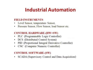
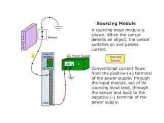
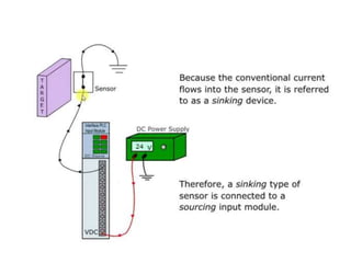
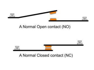
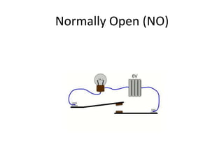
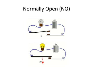
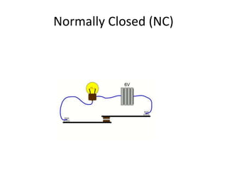
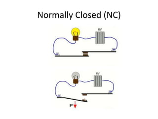
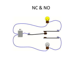
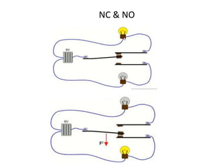
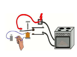
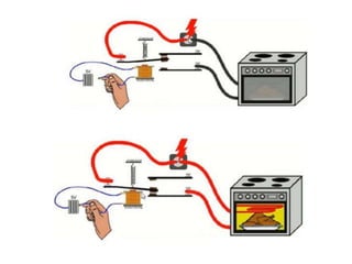
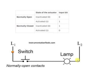
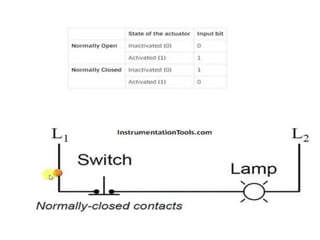
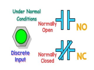
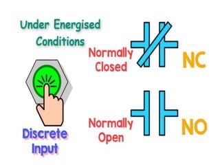
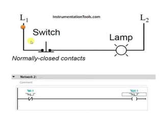
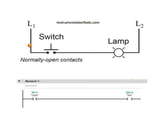
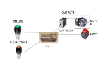
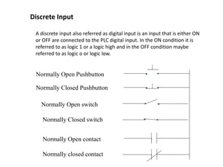
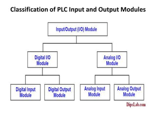
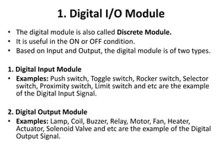
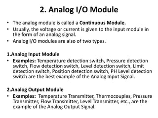
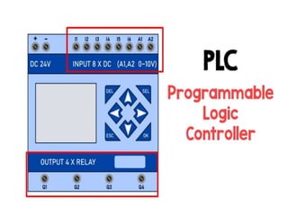
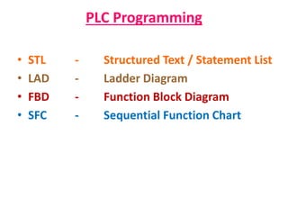
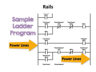
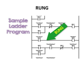
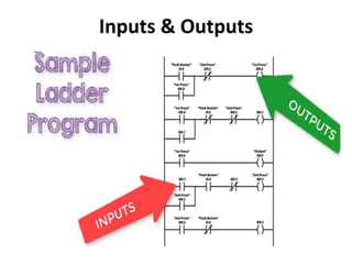
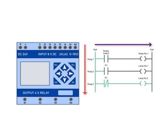
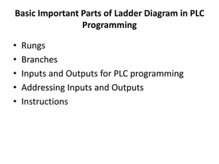
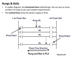
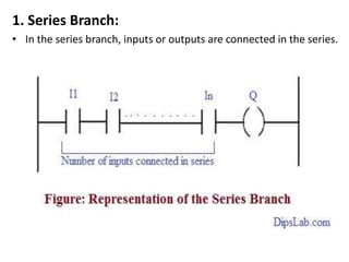
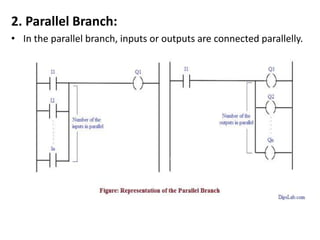
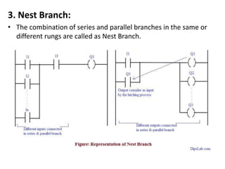
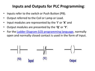
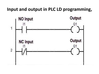
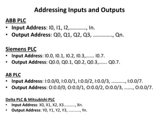
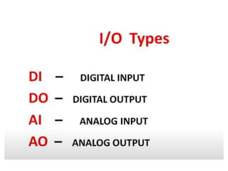
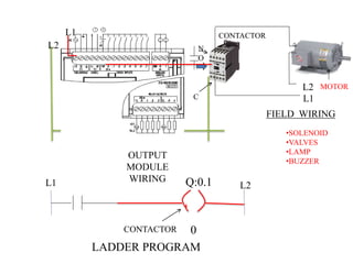
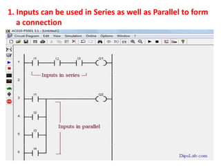
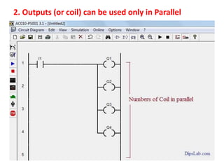
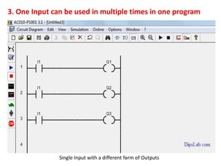
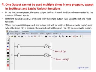
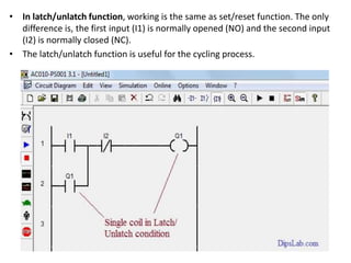
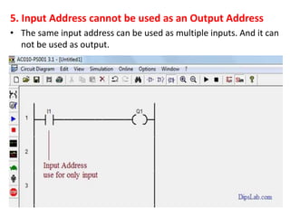
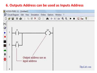
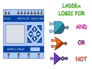
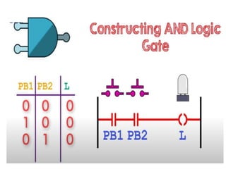
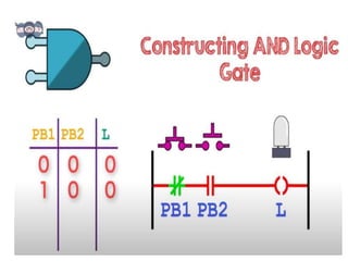
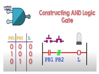
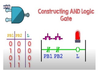
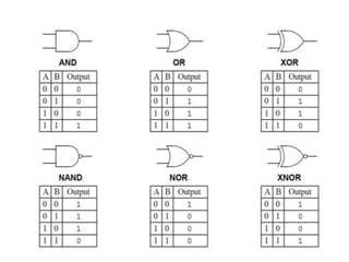
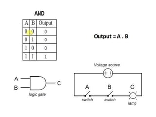
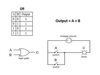
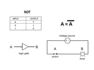
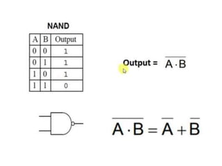
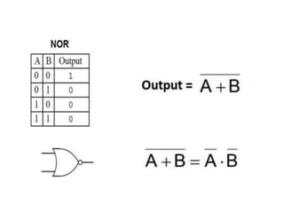
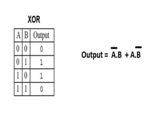
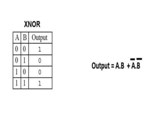
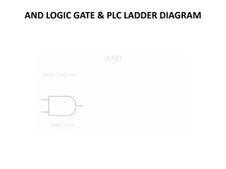
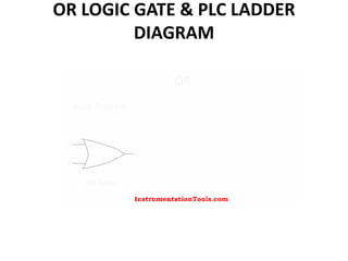
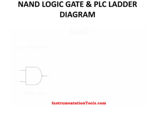
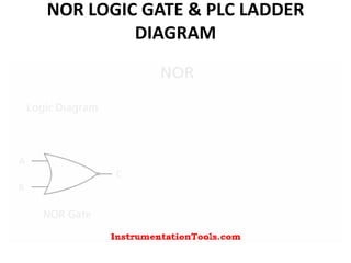
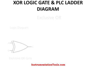
Industrial Automation
Normally Open (NO)
Normally Open (NO)
Normally Closed (NC)
NC & NO
NC & NO
PLC
INPUTS
OUTPUTS
MOTO
R
LAMP
CONTACTOR
PUSHBUTTONS
A discrete input also referred as digital input is an input that is either ON
or OFF are connected to the PLC digital input. In the ON condition it is
referred to as logic 1 or a logic high and in the OFF condition maybe
referred to as logic o or logic low.
Discrete Input
Normally Open Pushbutton
Normally Closed Pushbutton
Normally Open switch
Normally Closed switch
Normally Open contact
Normally closed contact
Classification of PLC Input and Output Modules
1. Digital I/O Module
• The digital module is also called Discrete Module.
• It is useful in the ON or OFF condition.
• Based on Input and Output, the digital module is of two types.
1. Digital Input Module
• Examples: Push switch, Toggle switch, Rocker switch, Selector
switch, Proximity switch, Limit switch and etc are the example
of the Digital Input Signal.
2. Digital Output Module
• Examples: Lamp, Coil, Buzzer, Relay, Motor, Fan, Heater,
Actuator, Solenoid Valve and etc are the example of the Digital
Output Signal.
2. Analog I/O Module
• The analog module is called a Continuous Module.
• Usually, the voltage or current is given to the input module in
the form of an analog signal.
• Analog I/O modules are also of two types.
1.Analog Input Module
• Examples: Temperature detection switch, Pressure detection
switch, Flow detection switch, Level detection switch, Limit
detection switch, Position detection switch, PH Level detection
switch are the best example of the Analog Input Signal.
2.Analog Output Module
• Examples: Temperature Transmitter, Thermocouples, Pressure
Transmitter, Flow Transmitter, Level Transmitter, etc., are the
example of the Analog Output Signal.
PLC Programming
PLC Programming
• STL - Structured Text / Statement List
• LAD - Ladder Diagram
• FBD - Function Block Diagram
• SFC - Sequential Function Chart
Rails
RUNG
Inputs & Outputs
Basic Important Parts of Ladder Diagram in PLC
Programming
• Rungs
• Branches
• Inputs and Outputs for PLC programming
• Addressing Inputs and Outputs
• Instructions
Rungs & Rails
• In Ladder diagram, the horizontal lines called Rungs. You can put as many
numbers of rungs as per your project requirements.
• The vertical lines show the power supply or flow.
1. Series Branch:
• In the series branch, inputs or outputs are connected in the series.
2. Parallel Branch:
• In the parallel branch, inputs or outputs are connected parallelly.
3. Nest Branch:
• The combination of series and parallel branches in the same or
different rungs are called as Nest Branch.
Inputs and Outputs for PLC Programming:
• Inputs refer to the switch or Push Button (PB).
• Output referred to the Coil or Lamp or Load.
• Input modules are represented by the ‘I‘ or ‘X‘ and
• Output modules are presented by the ‘Q‘ or ‘Y‘.
• For the Ladder Diagram (LD) programming language, normally
open and normally closed contact is used in the form of input.
Input and output in PLC LD programming,
Addressing Inputs and Outputs
ABB PLC
• Input Address: I0, I1, I2,…………, In.
• Output Address: Q0, Q1, Q2, Q3, ………….., Qn.
Siemens PLC
• Input Address: I0.0, I0.1, I0.2, I0.3,……. I0.7.
• Output Address: Q0.0, Q0.1, Q0.2, Q0.3,……. Q0.7.
AB PLC
• Input Address: I:0.0/0, I:0.0/1, I:0.0/2, I:0.0/3, ……….., I:0.0/7.
• Output Address: O:0.0/0, O:0.0/1, O:0.0/2, O:0.0/3, ……., O:0.0/7.
Delta PLC & Mitsubishi PLC
• Input Address: X0, X1, X2, X3……….., Xn.
• Output Address: Y0, Y1, Y2, Y3, ……….., Yn.
87
INPUT MODULE
WIRING DIAGRAM
LADDER PROGRAM
I:0.1
0
I= Input
Module
slot # in rack
Module
Terminal #
Siemens S7-1200
Address I:0.1
N.
O
C
L2
L1
L2
OUTPUT
MODULE
WIRING
MOTOR
CONTACTOR
Q:0.1
0
CONTACTOR
LADDER PROGRAM
L1 L2
FIELD WIRING
•SOLENOID
•VALVES
•LAMP
•BUZZER
L1
Advantage of the Ladder Diagram PLC Language
• The ladder diagram (LD) is a simple logic construction
and more reliable than an electronic circuit controller.
• Easy to learn and read the program.
• Every programming symbol performs specific actions.
• LD having good representation for discrete logic.
• Easy to troubleshoot.
• Shut down the power without the switch (i.e. hardware
devices).
1. Inputs can be used in Series as well as Parallel to form
a connection
2. Outputs (or coil) can be used only in Parallel
3. One Input can be used in multiple times in one program
Single Input with a different form of Outputs
4. One Output cannot be used multiple times in one program, except
in Set/Reset and Latch/ Unlatch functions
• In the function set/reset, the same output address is used. And it can be connected to the
same or different inputs.
• Different inputs (I1 and I2) are linked with the single output (Q1) using the set and reset
function.
• When the Input (I1) is pressed, the output coil will be set ( i.e. Q1 on activate mode). And
when the input (I2) is pressed, the output coil will be reset ( i.e. Q1 on deactivate mode).
• In latch/unlatch function, working is the same as set/reset function. The only
difference is, the first input (I1) is normally opened (NO) and the second input
(I2) is normally closed (NC).
• The latch/unlatch function is useful for the cycling process.
5. Input Address cannot be used as an Output Address
• The same input address can be used as multiple inputs. And it can
not be used as output.
6. Outputs Address can be used as Inputs Address
AND LOGIC GATE & PLC LADDER DIAGRAM
OR LOGIC GATE & PLC LADDER
DIAGRAM
NAND LOGIC GATE & PLC LADDER
DIAGRAM
NOR LOGIC GATE & PLC LADDER
DIAGRAM
XOR LOGIC GATE & PLC LADDER
DIAGRAM

BASIC COMPONENTS OF PLC NEW.ppt

  • 2.
  • 43.
  • 44.
  • 45.
  • 46.
  • 47.
  • 48.
  • 57.
  • 58.
    A discrete inputalso referred as digital input is an input that is either ON or OFF are connected to the PLC digital input. In the ON condition it is referred to as logic 1 or a logic high and in the OFF condition maybe referred to as logic o or logic low. Discrete Input Normally Open Pushbutton Normally Closed Pushbutton Normally Open switch Normally Closed switch Normally Open contact Normally closed contact
  • 59.
    Classification of PLCInput and Output Modules
  • 60.
    1. Digital I/OModule • The digital module is also called Discrete Module. • It is useful in the ON or OFF condition. • Based on Input and Output, the digital module is of two types. 1. Digital Input Module • Examples: Push switch, Toggle switch, Rocker switch, Selector switch, Proximity switch, Limit switch and etc are the example of the Digital Input Signal. 2. Digital Output Module • Examples: Lamp, Coil, Buzzer, Relay, Motor, Fan, Heater, Actuator, Solenoid Valve and etc are the example of the Digital Output Signal.
  • 61.
    2. Analog I/OModule • The analog module is called a Continuous Module. • Usually, the voltage or current is given to the input module in the form of an analog signal. • Analog I/O modules are also of two types. 1.Analog Input Module • Examples: Temperature detection switch, Pressure detection switch, Flow detection switch, Level detection switch, Limit detection switch, Position detection switch, PH Level detection switch are the best example of the Analog Input Signal. 2.Analog Output Module • Examples: Temperature Transmitter, Thermocouples, Pressure Transmitter, Flow Transmitter, Level Transmitter, etc., are the example of the Analog Output Signal.
  • 65.
  • 67.
    PLC Programming • STL- Structured Text / Statement List • LAD - Ladder Diagram • FBD - Function Block Diagram • SFC - Sequential Function Chart
  • 70.
  • 71.
  • 72.
  • 74.
    Basic Important Partsof Ladder Diagram in PLC Programming • Rungs • Branches • Inputs and Outputs for PLC programming • Addressing Inputs and Outputs • Instructions
  • 75.
    Rungs & Rails •In Ladder diagram, the horizontal lines called Rungs. You can put as many numbers of rungs as per your project requirements. • The vertical lines show the power supply or flow.
  • 76.
    1. Series Branch: •In the series branch, inputs or outputs are connected in the series.
  • 77.
    2. Parallel Branch: •In the parallel branch, inputs or outputs are connected parallelly.
  • 78.
    3. Nest Branch: •The combination of series and parallel branches in the same or different rungs are called as Nest Branch.
  • 79.
    Inputs and Outputsfor PLC Programming: • Inputs refer to the switch or Push Button (PB). • Output referred to the Coil or Lamp or Load. • Input modules are represented by the ‘I‘ or ‘X‘ and • Output modules are presented by the ‘Q‘ or ‘Y‘. • For the Ladder Diagram (LD) programming language, normally open and normally closed contact is used in the form of input.
  • 80.
    Input and outputin PLC LD programming,
  • 81.
    Addressing Inputs andOutputs ABB PLC • Input Address: I0, I1, I2,…………, In. • Output Address: Q0, Q1, Q2, Q3, ………….., Qn. Siemens PLC • Input Address: I0.0, I0.1, I0.2, I0.3,……. I0.7. • Output Address: Q0.0, Q0.1, Q0.2, Q0.3,……. Q0.7. AB PLC • Input Address: I:0.0/0, I:0.0/1, I:0.0/2, I:0.0/3, ……….., I:0.0/7. • Output Address: O:0.0/0, O:0.0/1, O:0.0/2, O:0.0/3, ……., O:0.0/7. Delta PLC & Mitsubishi PLC • Input Address: X0, X1, X2, X3……….., Xn. • Output Address: Y0, Y1, Y2, Y3, ……….., Yn.
  • 87.
    87 INPUT MODULE WIRING DIAGRAM LADDERPROGRAM I:0.1 0 I= Input Module slot # in rack Module Terminal # Siemens S7-1200 Address I:0.1
  • 88.
  • 89.
    Advantage of theLadder Diagram PLC Language • The ladder diagram (LD) is a simple logic construction and more reliable than an electronic circuit controller. • Easy to learn and read the program. • Every programming symbol performs specific actions. • LD having good representation for discrete logic. • Easy to troubleshoot. • Shut down the power without the switch (i.e. hardware devices).
  • 91.
    1. Inputs canbe used in Series as well as Parallel to form a connection
  • 92.
    2. Outputs (orcoil) can be used only in Parallel
  • 93.
    3. One Inputcan be used in multiple times in one program Single Input with a different form of Outputs
  • 94.
    4. One Outputcannot be used multiple times in one program, except in Set/Reset and Latch/ Unlatch functions • In the function set/reset, the same output address is used. And it can be connected to the same or different inputs. • Different inputs (I1 and I2) are linked with the single output (Q1) using the set and reset function. • When the Input (I1) is pressed, the output coil will be set ( i.e. Q1 on activate mode). And when the input (I2) is pressed, the output coil will be reset ( i.e. Q1 on deactivate mode).
  • 95.
    • In latch/unlatchfunction, working is the same as set/reset function. The only difference is, the first input (I1) is normally opened (NO) and the second input (I2) is normally closed (NC). • The latch/unlatch function is useful for the cycling process.
  • 96.
    5. Input Addresscannot be used as an Output Address • The same input address can be used as multiple inputs. And it can not be used as output.
  • 97.
    6. Outputs Addresscan be used as Inputs Address
  • 113.
    AND LOGIC GATE& PLC LADDER DIAGRAM
  • 114.
    OR LOGIC GATE& PLC LADDER DIAGRAM
  • 115.
    NAND LOGIC GATE& PLC LADDER DIAGRAM
  • 116.
    NOR LOGIC GATE& PLC LADDER DIAGRAM
  • 117.
    XOR LOGIC GATE& PLC LADDER DIAGRAM