INTRODUCTION
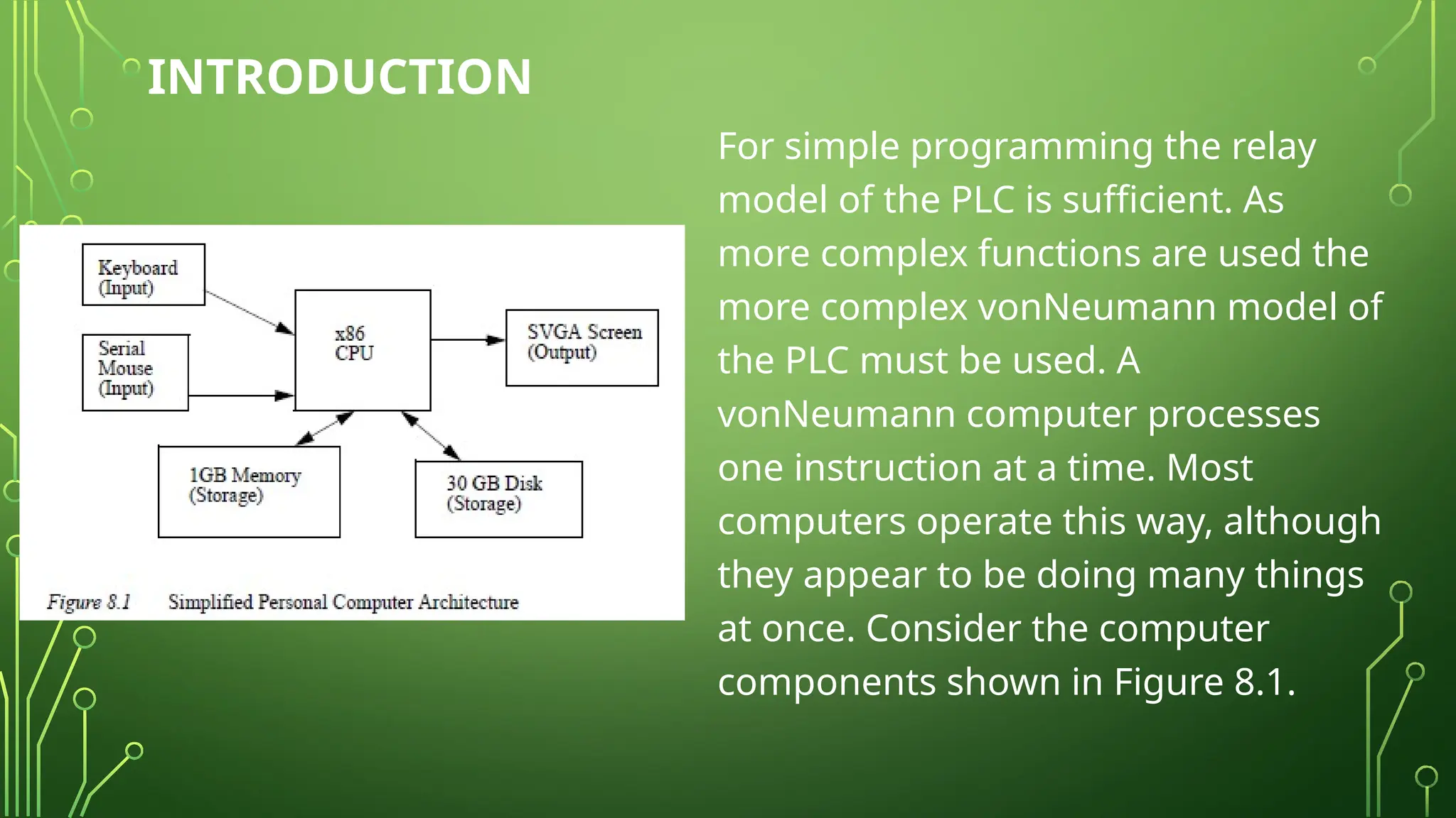
For simple programmingthe relay
model of the PLC is sufficient. As
more complex functions are used the
more complex vonNeumann model of
the PLC must be used. A
vonNeumann computer processes
one instruction at a time. Most
computers operate this way, although
they appear to be doing many things
at once. Consider the computer
components shown in Figure 8.1.
3.
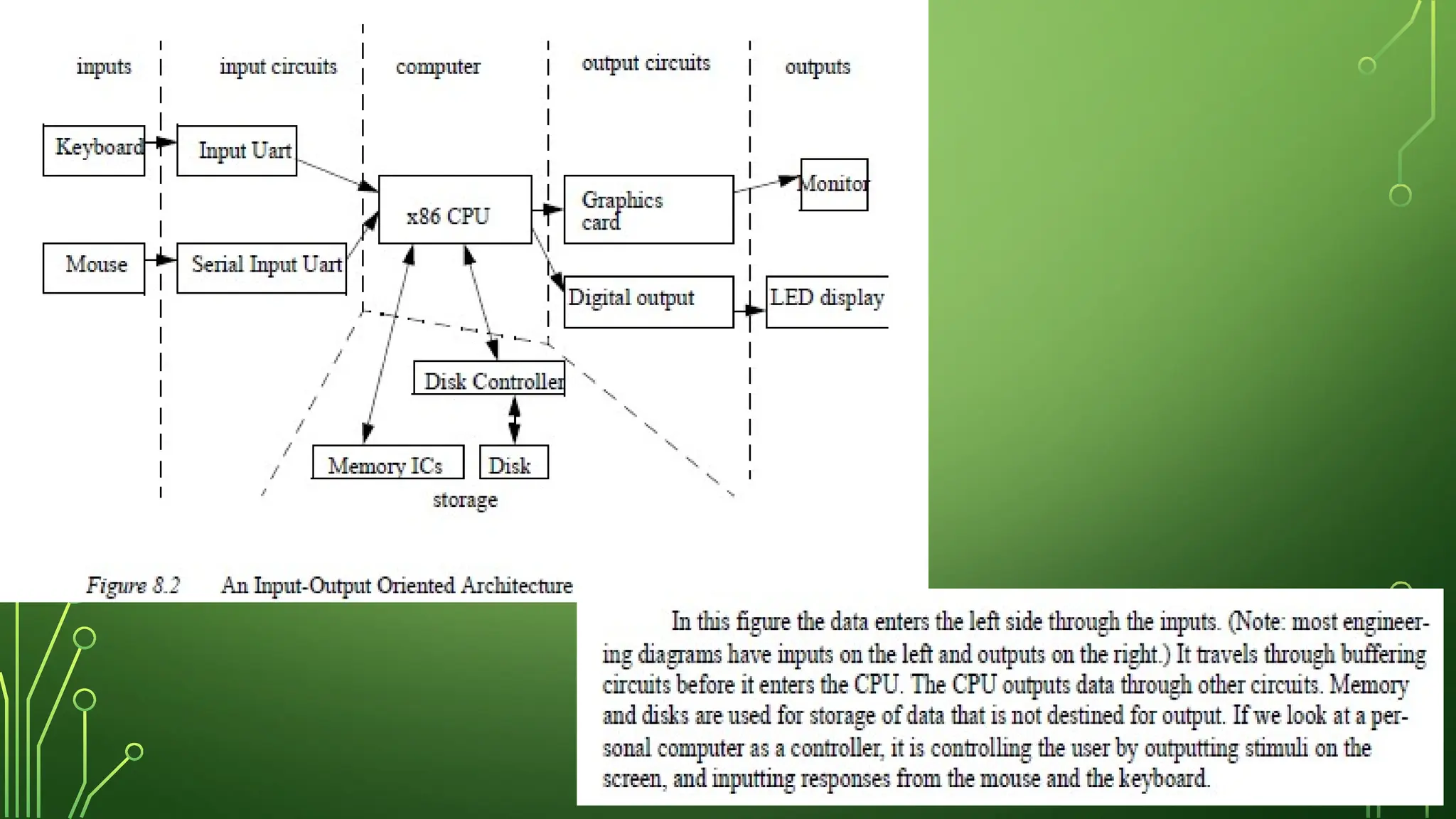
Input is obtainedfrom the keyboard and mouse,
output is sent to the screen, and the disk and
memory are used for both input and output for
storage. (Note: the directions of these arrows
are very important to engineers, always pay
attention to indicate where information is
flowing.) This figure can be redrawn as in Figure
8.2 to clarify the role of inputs and outputs.
All PLCs havefour basic stages of operations that are repeated many
times per second. Initially when turned on the first time it will check it’s
own hardware and software for faults. If there are no problems it will
copy all the input and copy their values into memory, this is called the
input scan. Using only the memory copy of the inputs the ladder logic
program will be solved once, this is called the logic scan. While solving
the ladder logic the output values are only changed in temporary
memory. When the ladder scan is done the outputs will updated using
the temporary values in memory, this is called the output scan. The
PLC now restarts the process by starting a self check for faults. This
process typically repeats 10 to 100 times per second as is shown in
Figure 8.3.
9.
The input andoutput scans often confuse the beginner, but
they are important. The input scan takes a snapshot of the
inputs, and solves the logic. This prevents potential
problems that might occur if an input that is used in
multiple places in the ladder logic program changed while
half way through a ladder scan. Thus changing the
behaviors of half of the ladder logic program. This problem
could have severe effects on complex programs that are
developed later in the book. One side effect of the input
scan is that if a change in input is too short in duration, it
might fall between input scans and be missed.
10.
When the PLCis initially turned on
the normal outputs will be turned
off. This does not affect the values
of the inputs.
11.
THE INPUT ANDOUTPUT SCANS
When the inputs to the PLC are scanned the physical input
values are copied into memory. When the outputs to a PLC are
scanned they are copied from memory to the physical outputs.
When the ladder logic is scanned it uses the values in memory,
not the actual input or output values. The primary reason for
doing this is so that if a program uses an input value in multiple
places, a change in the input value will not invalidate the logic.
Also, if output bits were changed as each bit was changed,
instead of all at once at the end of the scan the PLC would
operate much slower.
12.
THE LOGIC SCAN
Ladderlogic programs are modelled after relay
logic. In relay logic each element in the ladder
will switch as quickly as possible. But in a
program elements can only be examines one at
a time in a fixed sequence. Consider the ladder
logic in Figure 8.4, the ladder logic will be
interpreted left-to-right, top-to-bottom. In the
figure the ladder logic scan begins at the top
rung. At the end of the rung it interprets the top
output first, then the output branched below it.
On the second rung it solves branches, before
moving along the ladder logic rung.
13.
The logic scansequence become important when solving ladder logic programs which
use outputs as inputs, as we will see in Chapter 8. It also becomes important when
considering output usage. Consider Figure 8.5, the first line of ladder logic will examine
input A and set output X to have the same value. The second line will examine input B
and set the output X to have the opposite value. So the value of X was only equal to A
until the second line of ladder logic was scanned. Recall that during the logic scan the
outputs are only changed in memory, the actual outputs are only updated when the
ladder logic scan is complete. Therefore the output scan would update the real outputs
based upon the second line of ladder logic, and the first line of ladder logic would be
ineffective.
These lights arenormally used for debugging. Limited
buttons will also be provided for PLC hardware. The most
common will be a run/program switch that will be
switched to program when maintenance is being
conducted, and back to run when in production. This
switch normally requires a key to keep unauthorized
personnel from altering the PLC program or stopping
execution. A PLC will almost never have an on-off switch
or reset button on the front. This needs to be designed
into the remainder of the system.
SOFTWARE BASED PLCS
Thedropping cost of personal computers is increasing their
use in control, including the replacement of PLCs. Software
is installed that allows the personal computer to solve
ladder logic, read inputs from sensors and update outputs
to actuators. These are important to mention here because
they don’t obey the previous timing model. For example, if
the computer is running a game it may slow or halt the
computer. This issue and others are currently being
investigated and good solutions should be expected soon.
20.
SUMMARY
•A PLC andcomputer are similar with inputs, outputs,
memory, etc.
•The PLC continuously goes through a cycle including a sanity
check, input scan, logic scan, and output scan.
•While the logic is being scanned, changes in the inputs are
not detected, and the outputs are not updated.
•PLCs use RAM, and sometime EPROMs are used for
permanent programs.