Downloaded 14 times

A PLC is a specialized computer used to monitor industrial processes and control machinery. It can be programmed using ladder logic to read input signals from sensors and control outputs to actuators. A PLC system includes an input module to read sensors, an output module to control actuators, a power supply, and a CPU module containing a processor and memory. PLCs offer advantages over relay-based control systems like larger numbers of inputs/outputs, lower cost, easier programming and troubleshooting, and reliability. Common instructions include examine if closed/open to check inputs, and output energize/latch/unlatch to control outputs. Timers allow timing functions like delays and pulse widths to be programmed. PLCs repeatedly
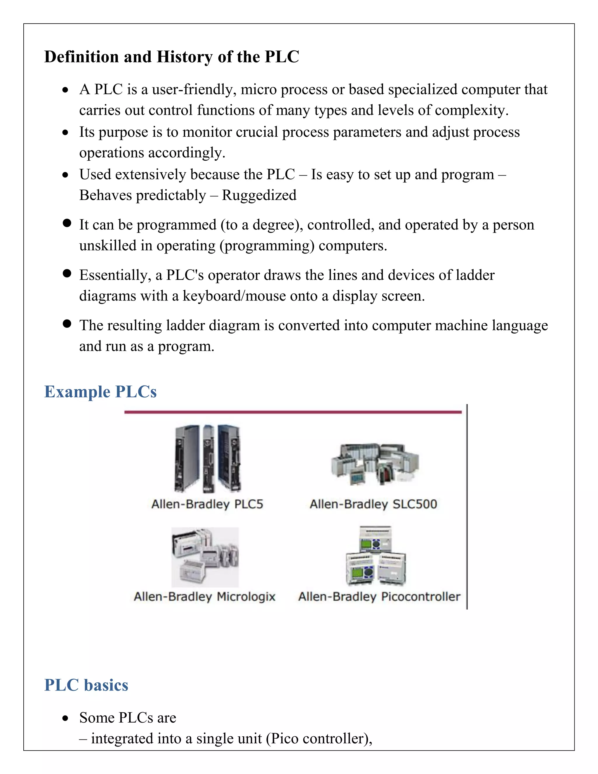
A PLC is a microprocessor-based computer for control functions. Types include integrated (Pico) and modular (PLC5, SLC500), each serving unique I/O functionalities.
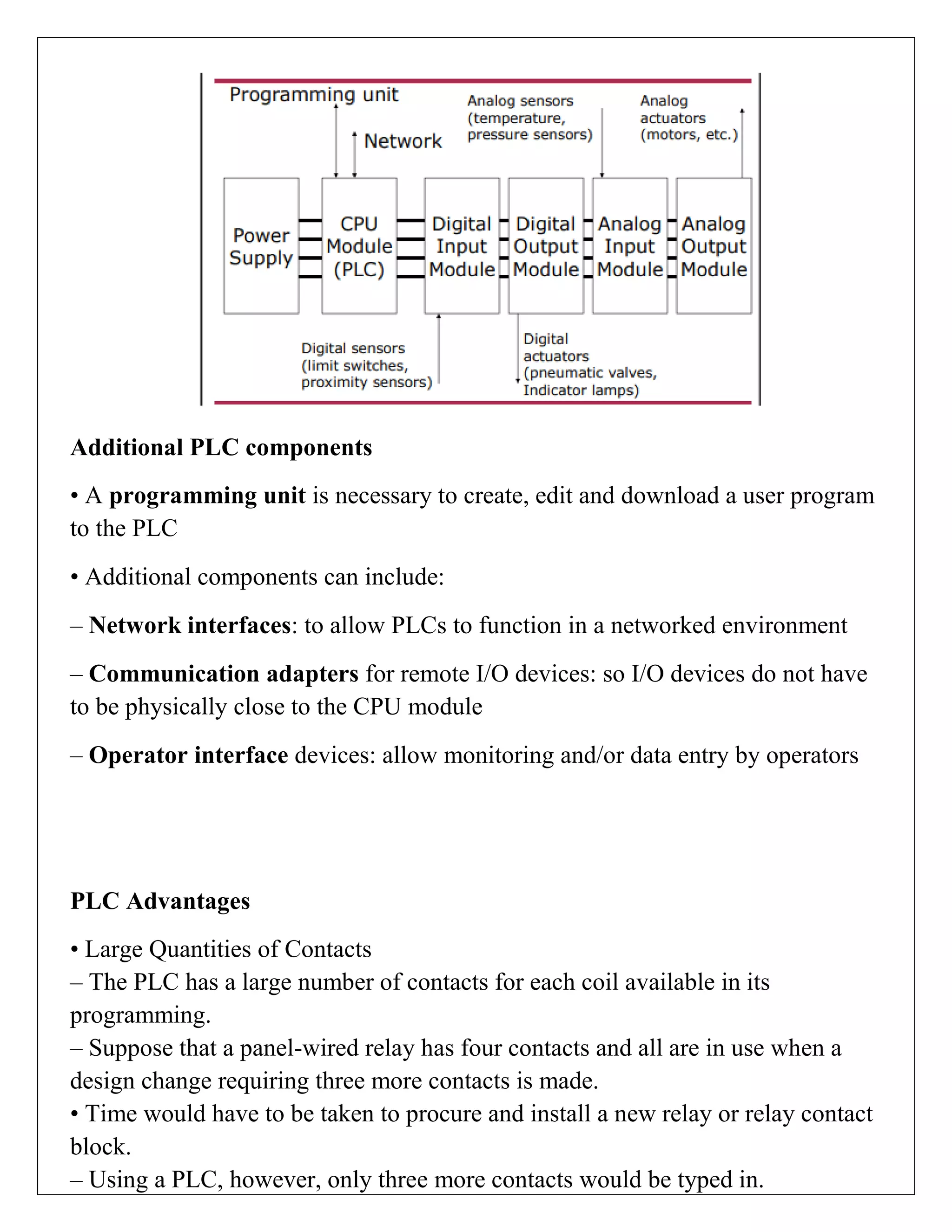
PLC systems include CPU, I/O modules, programming units, and interfaces. Advantages are lower costs, easy maintenance, and extensive input/output contacts.
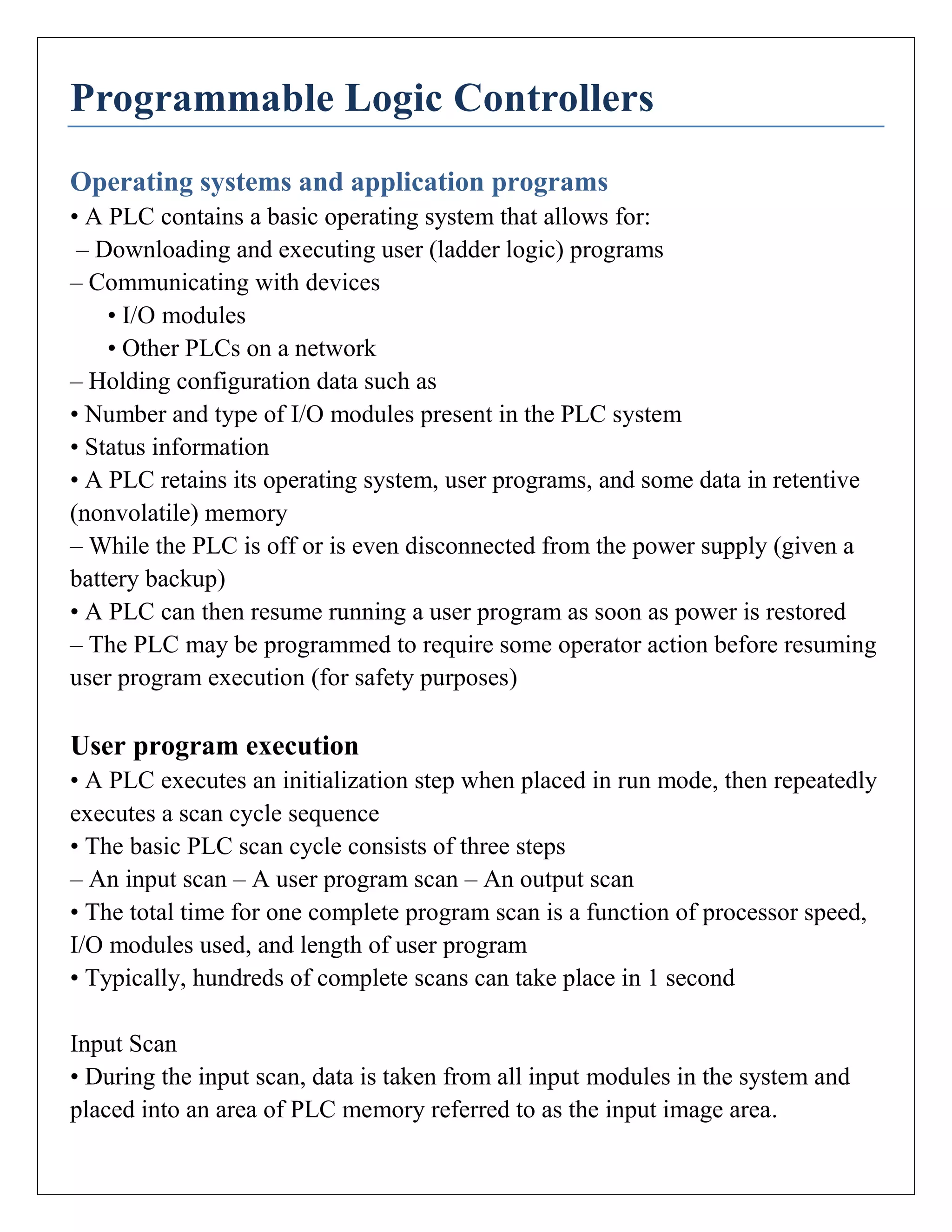
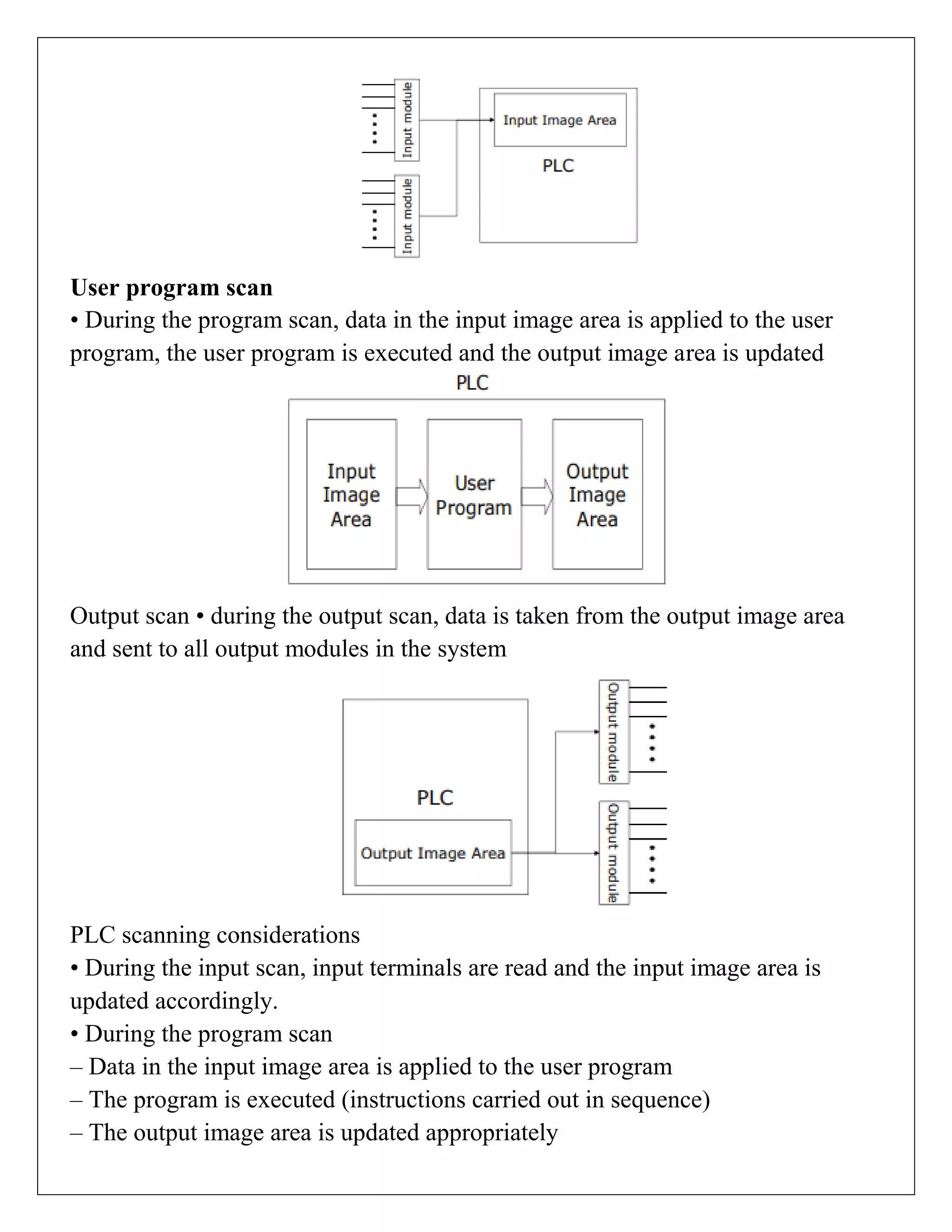
PLCs operate using a basic OS for executing programs via input, user program, and output scans, facilitating fast cycle times for robust automation.
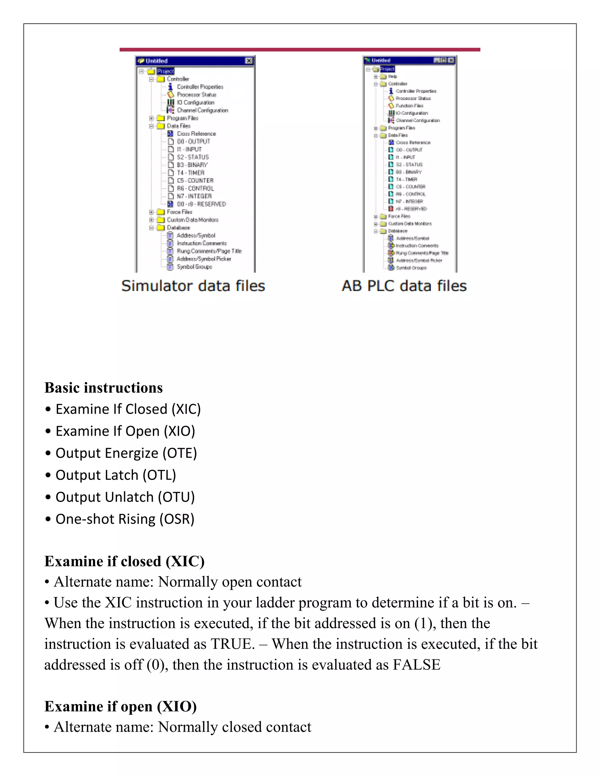
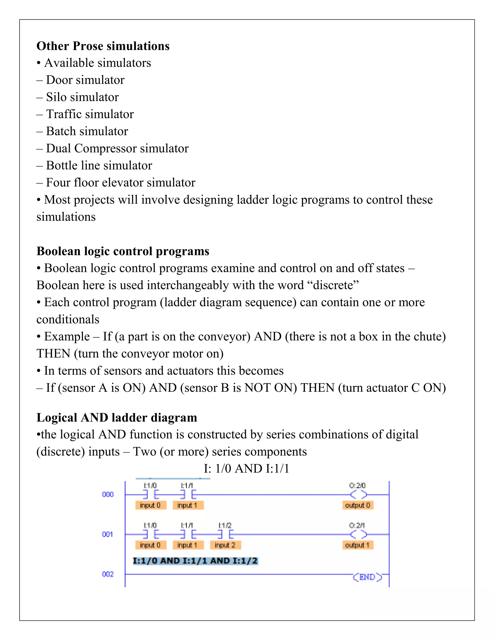
Basic PLC instructions include XIC, XIO, OTE, and others to control logic operations. These are fundamental to programming and create operational efficiency.
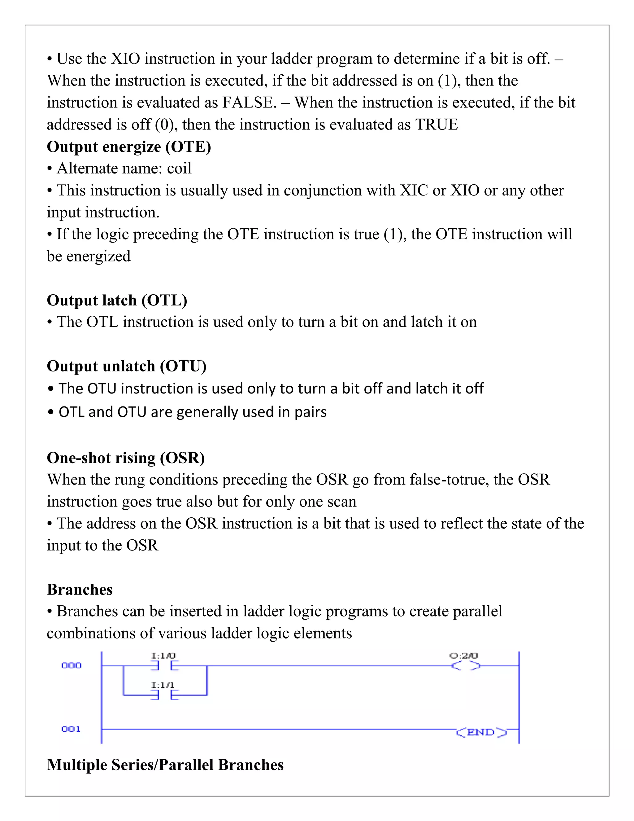
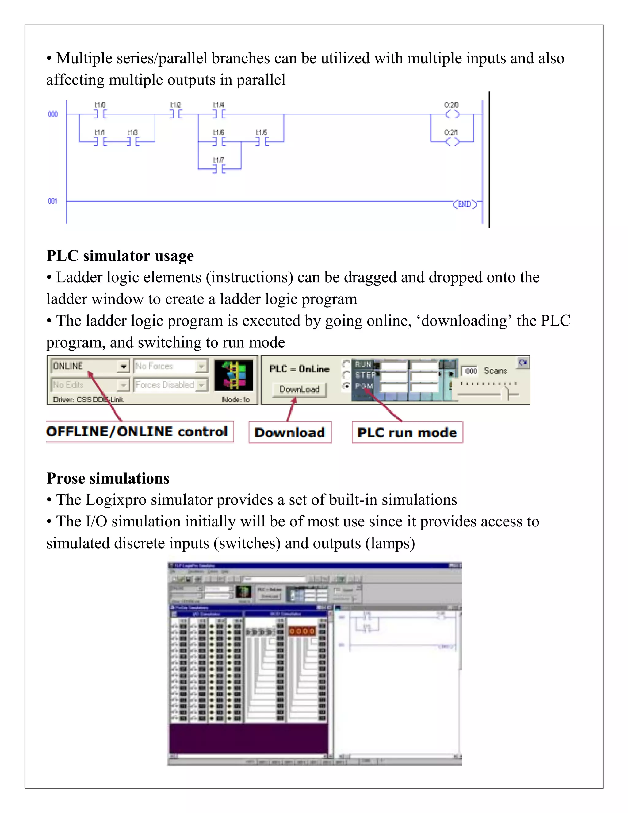
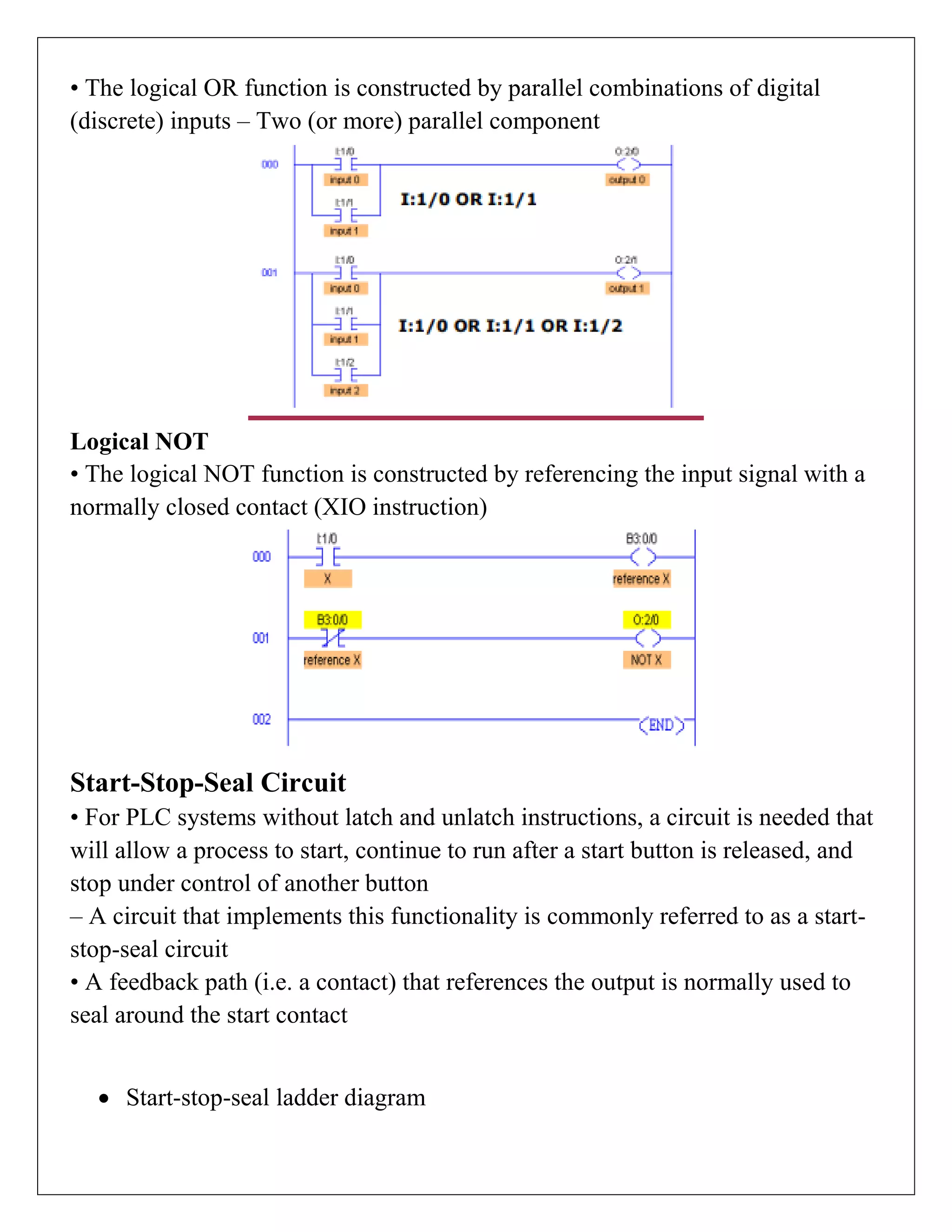
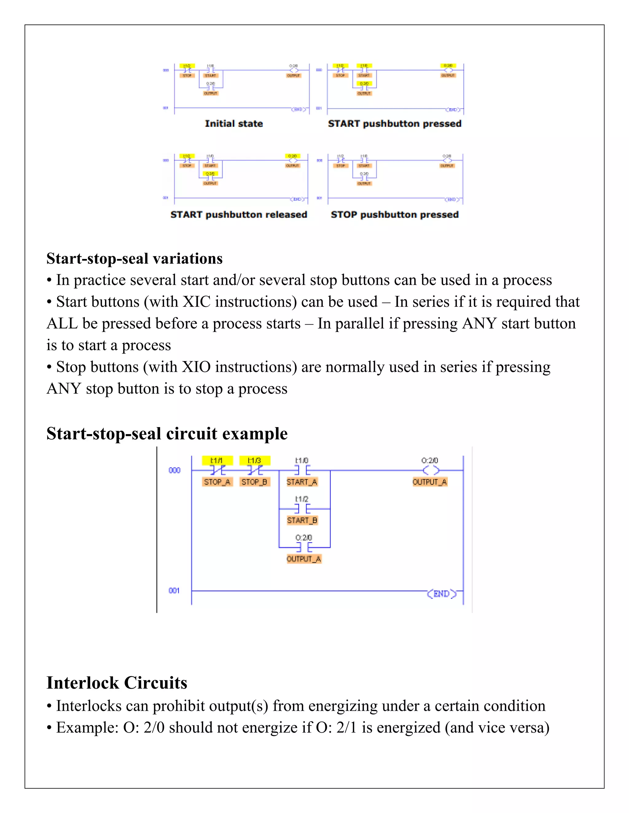
Multiple branches in PLCs allow for complex logic operations using series and parallel configurations, facilitating diverse process controls and interlocks.
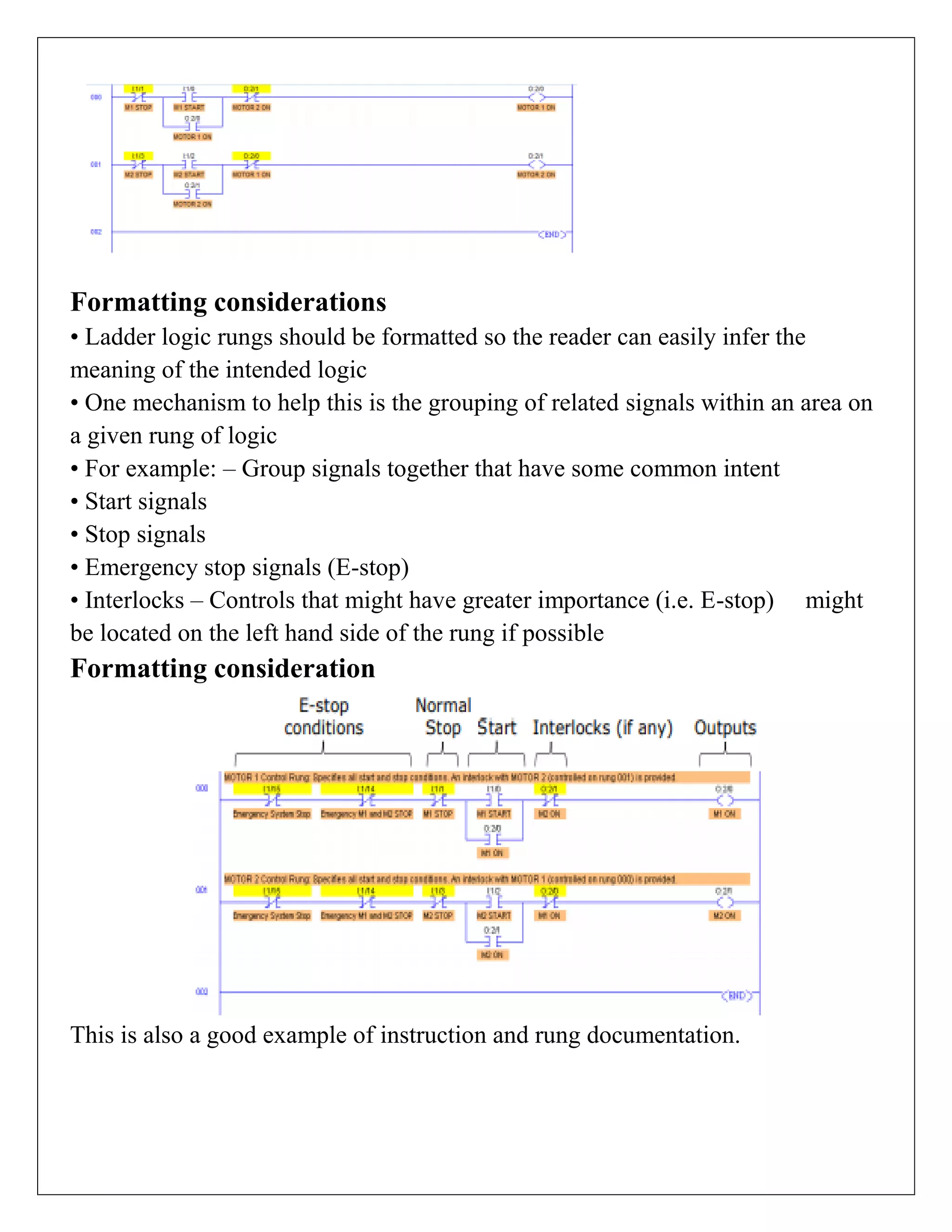
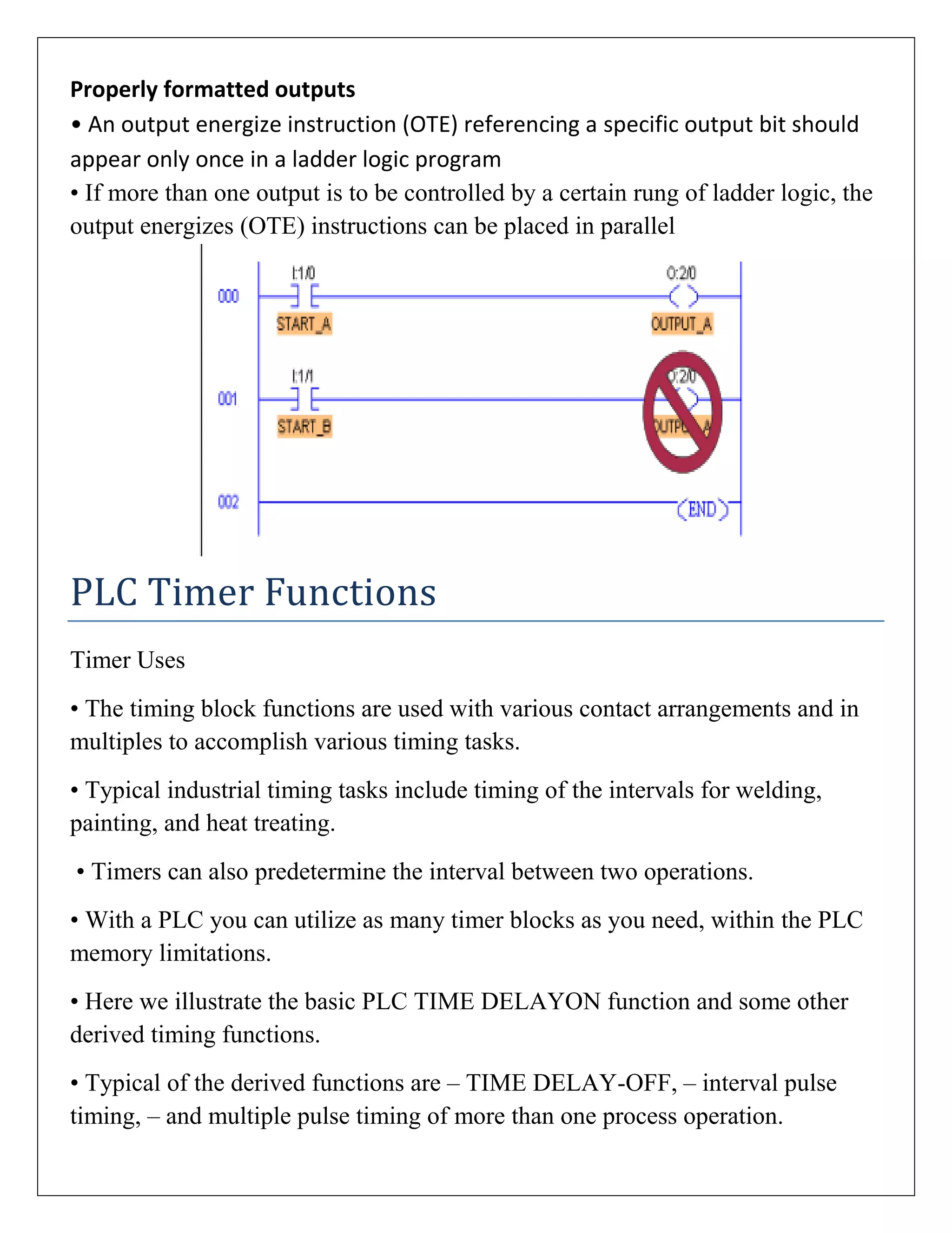
Proper formatting of ladder logic improves readability and ensures safety in operations, with guidelines for output instructions and documentation.
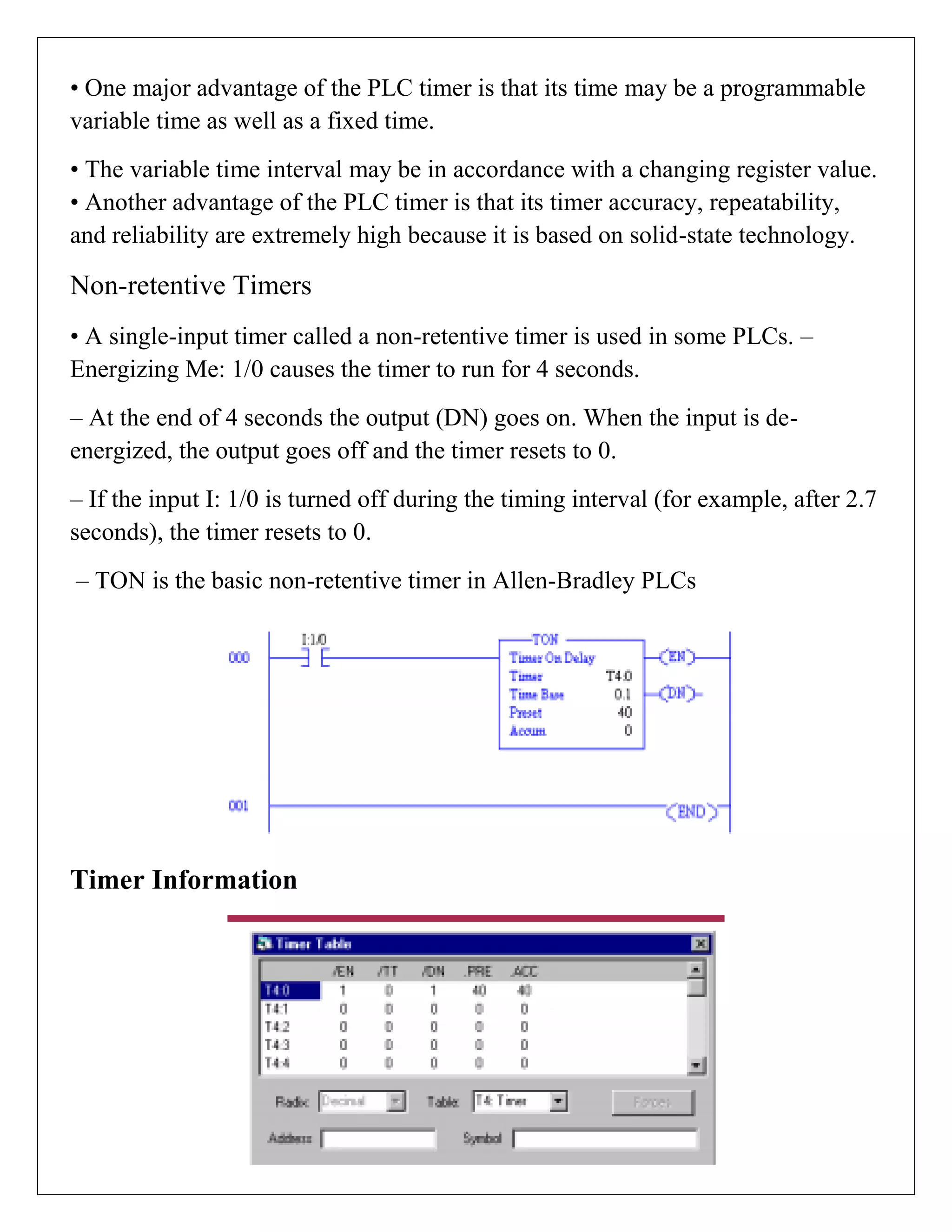
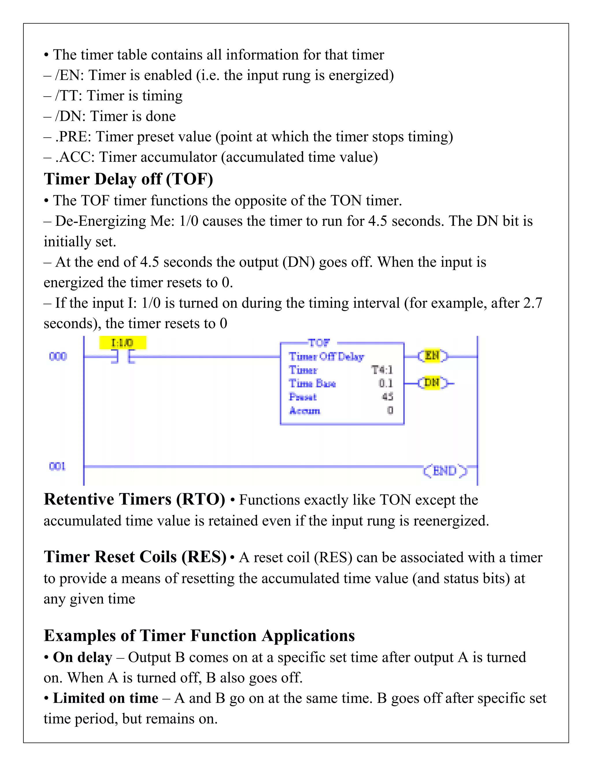
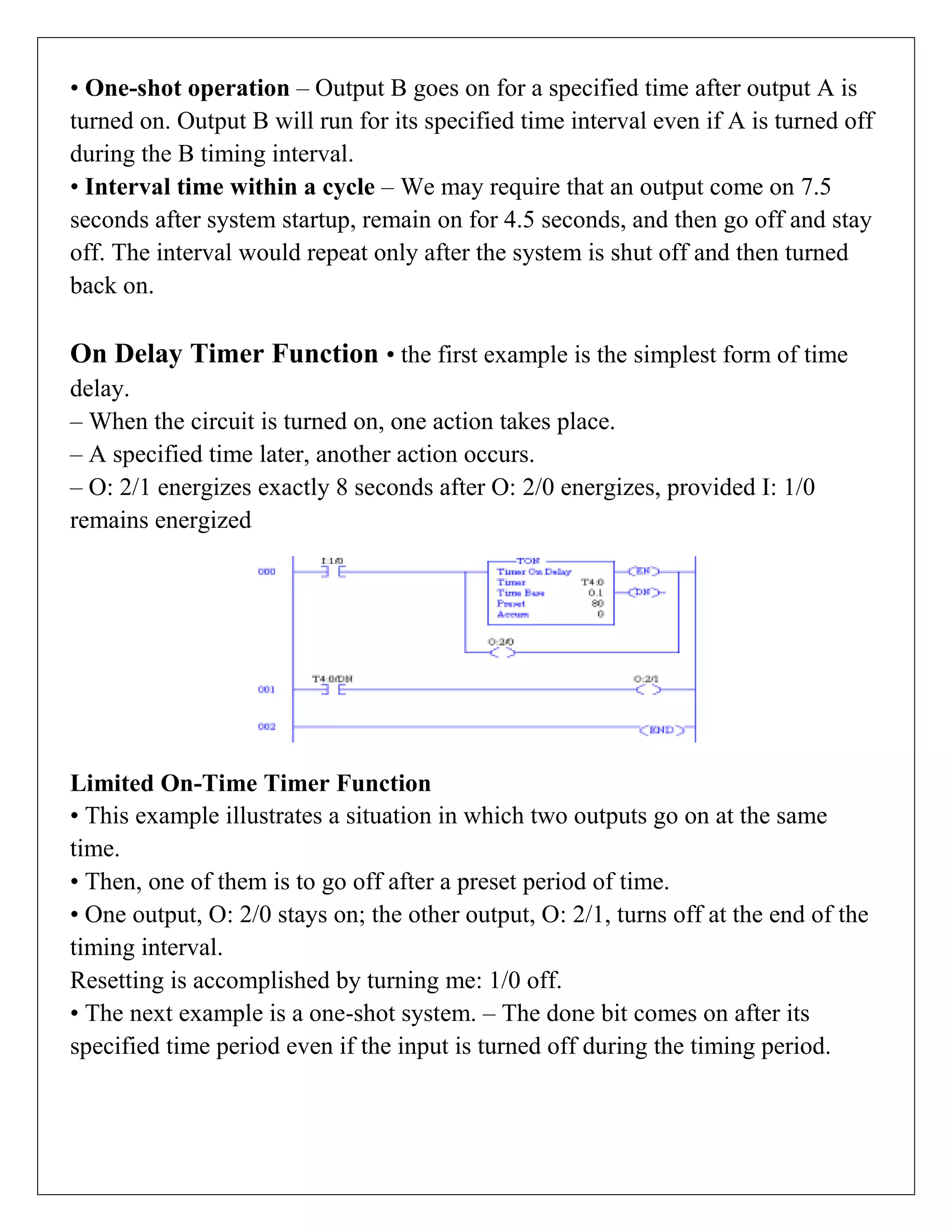
Timers in PLCs allow for set intervals and precise control of operations, with functions like ON delay and OFF delay enabling flexible process timing.
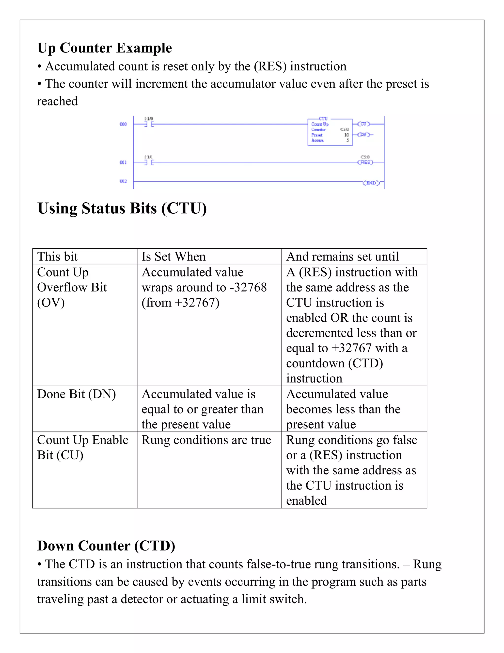
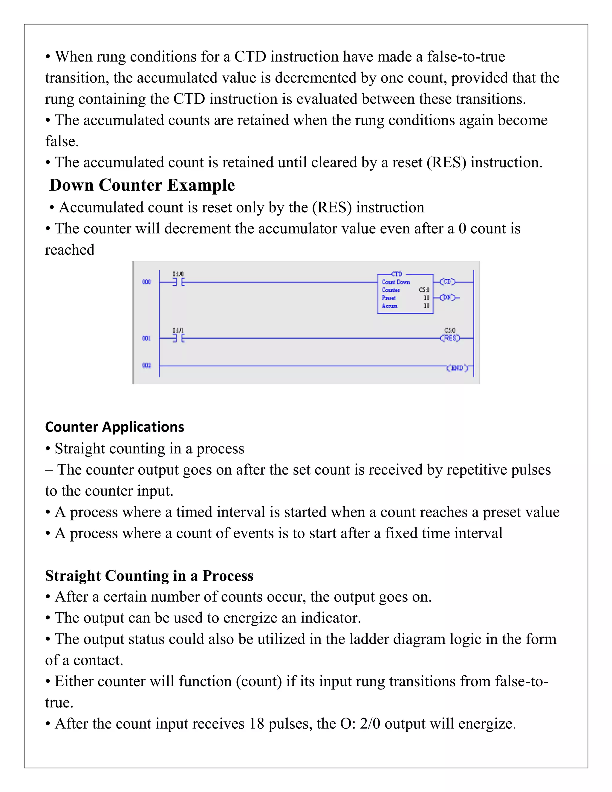
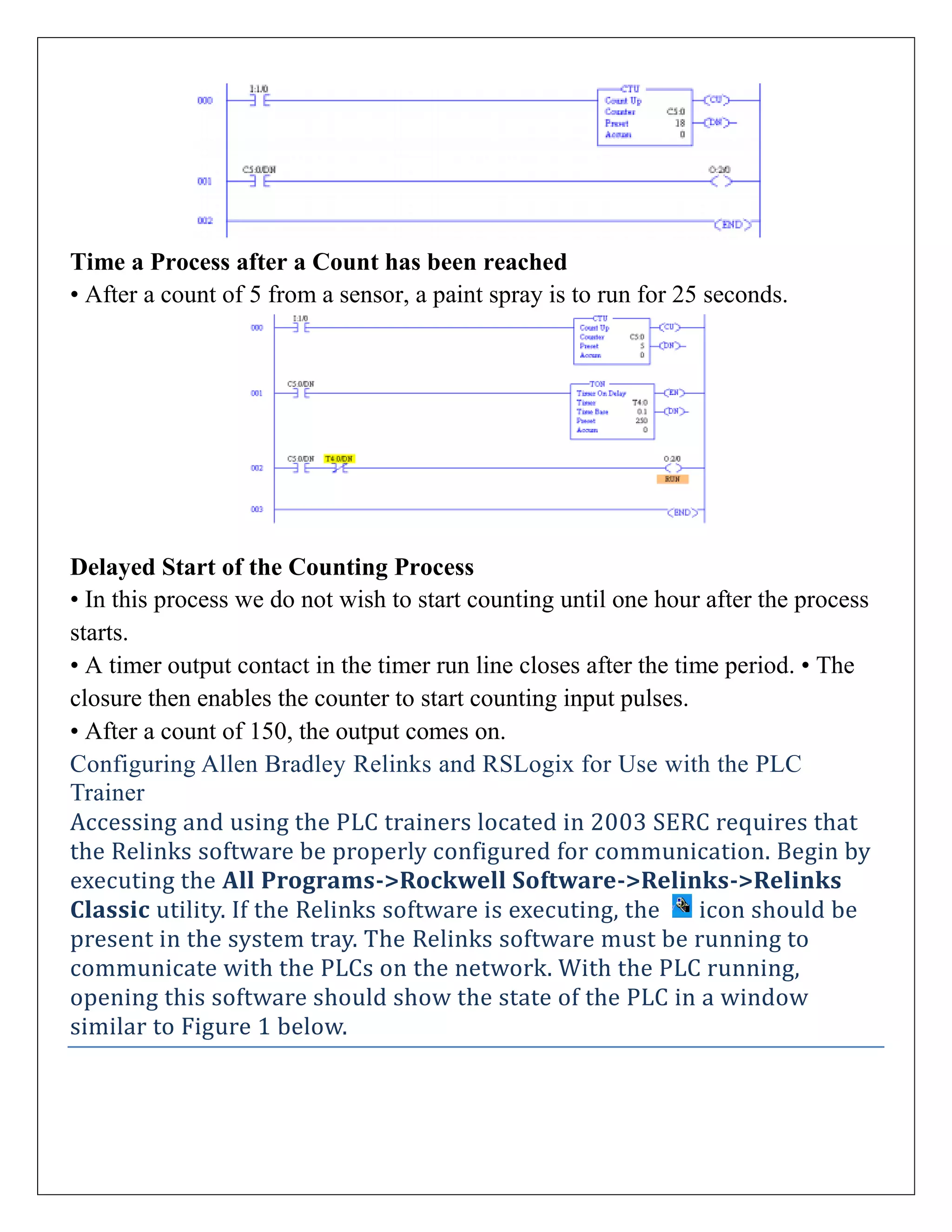
Counters operate similarly to timers, counting transitions for precise process tracking, useful in various applications affecting automation timing.
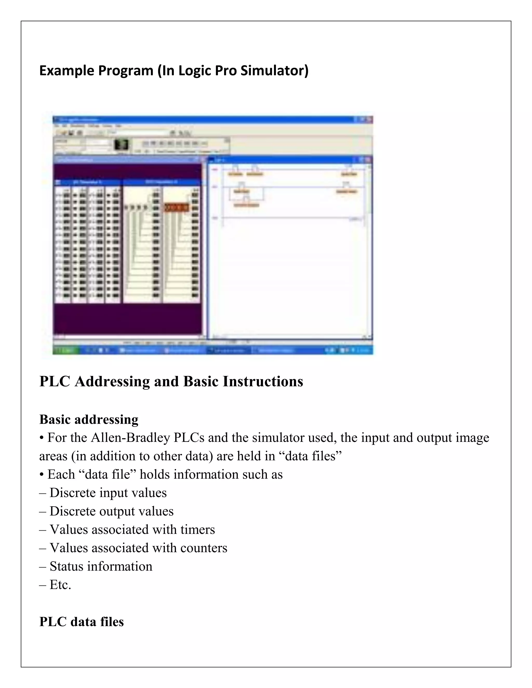
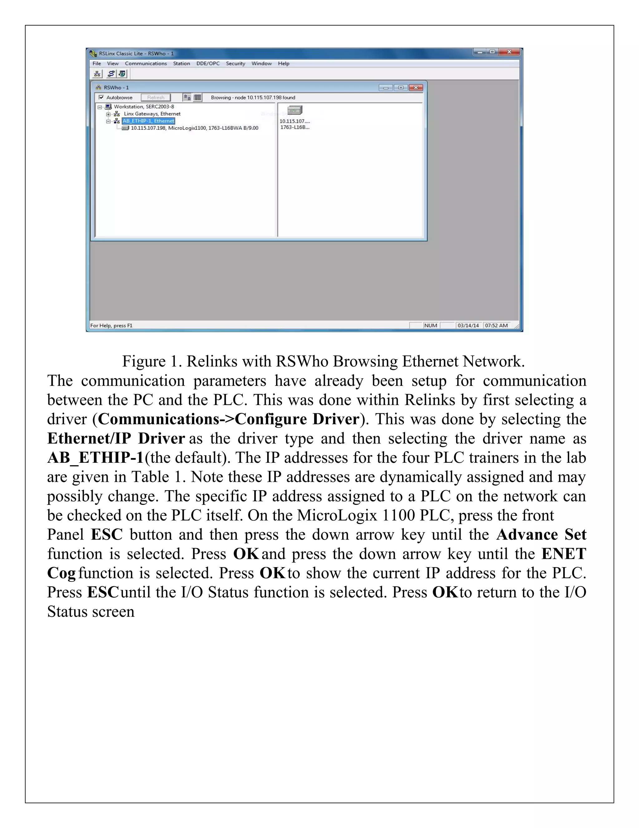
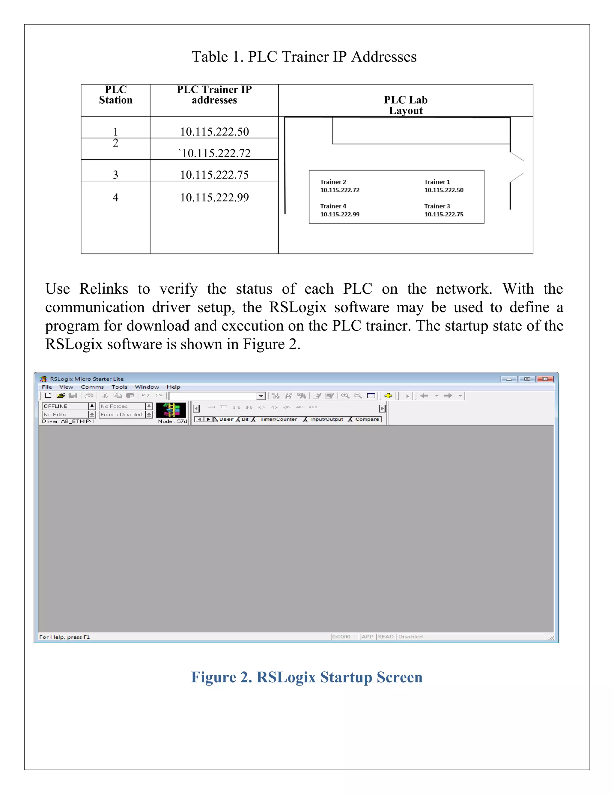
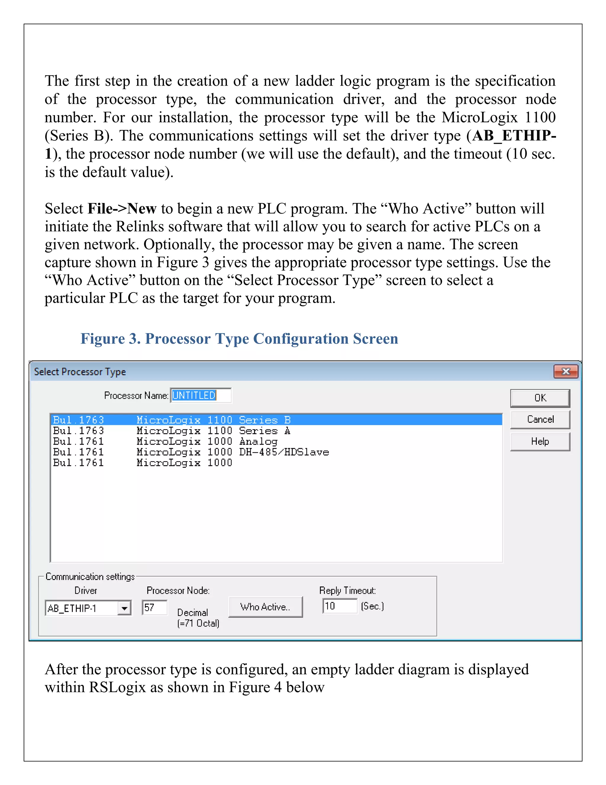
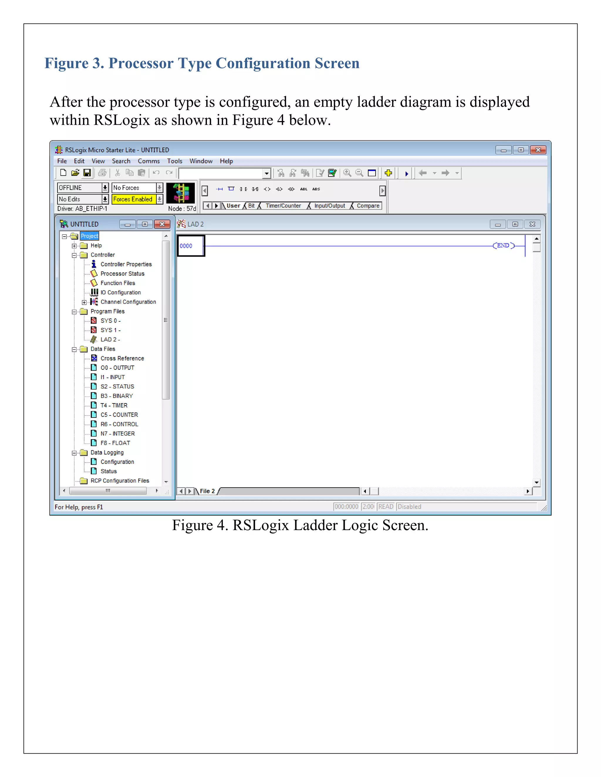
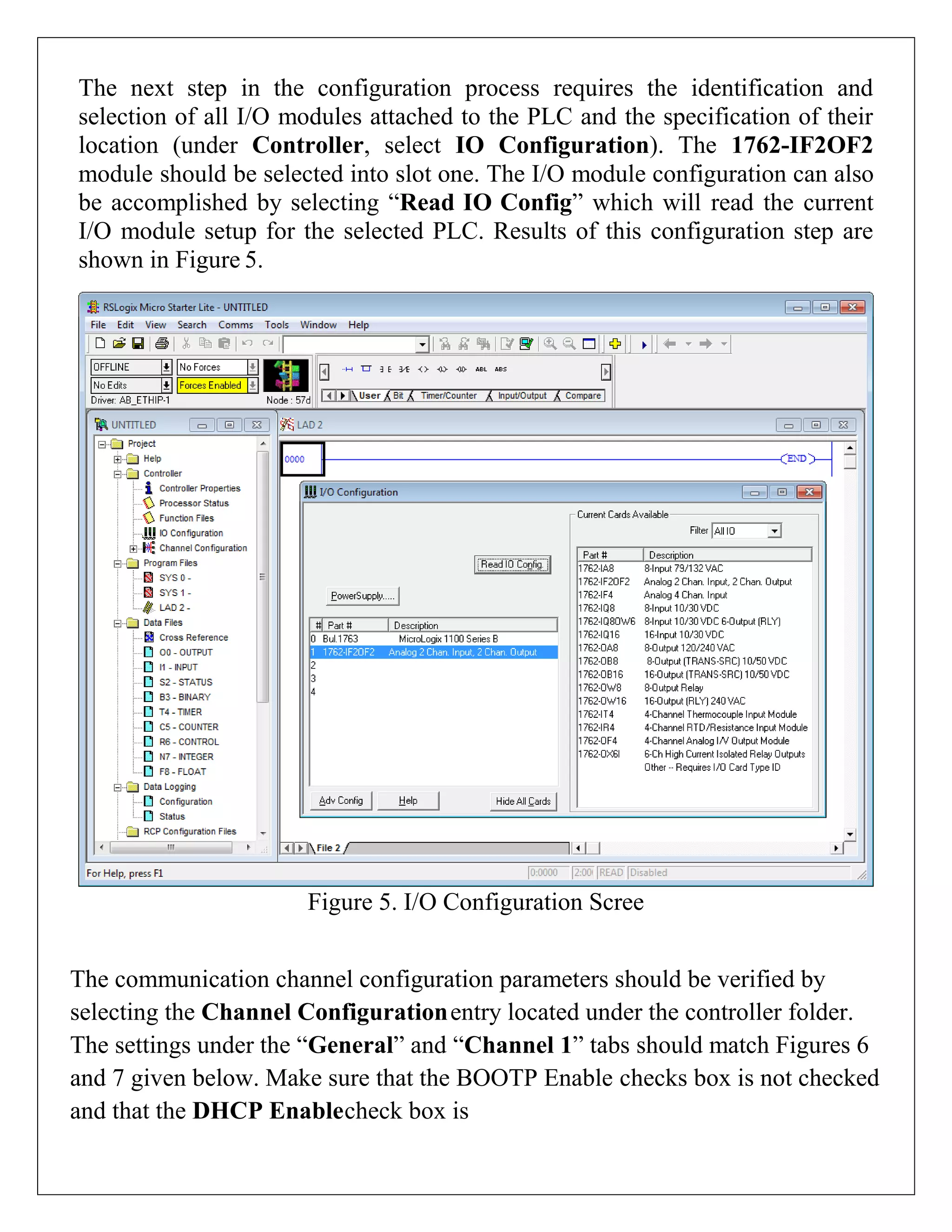
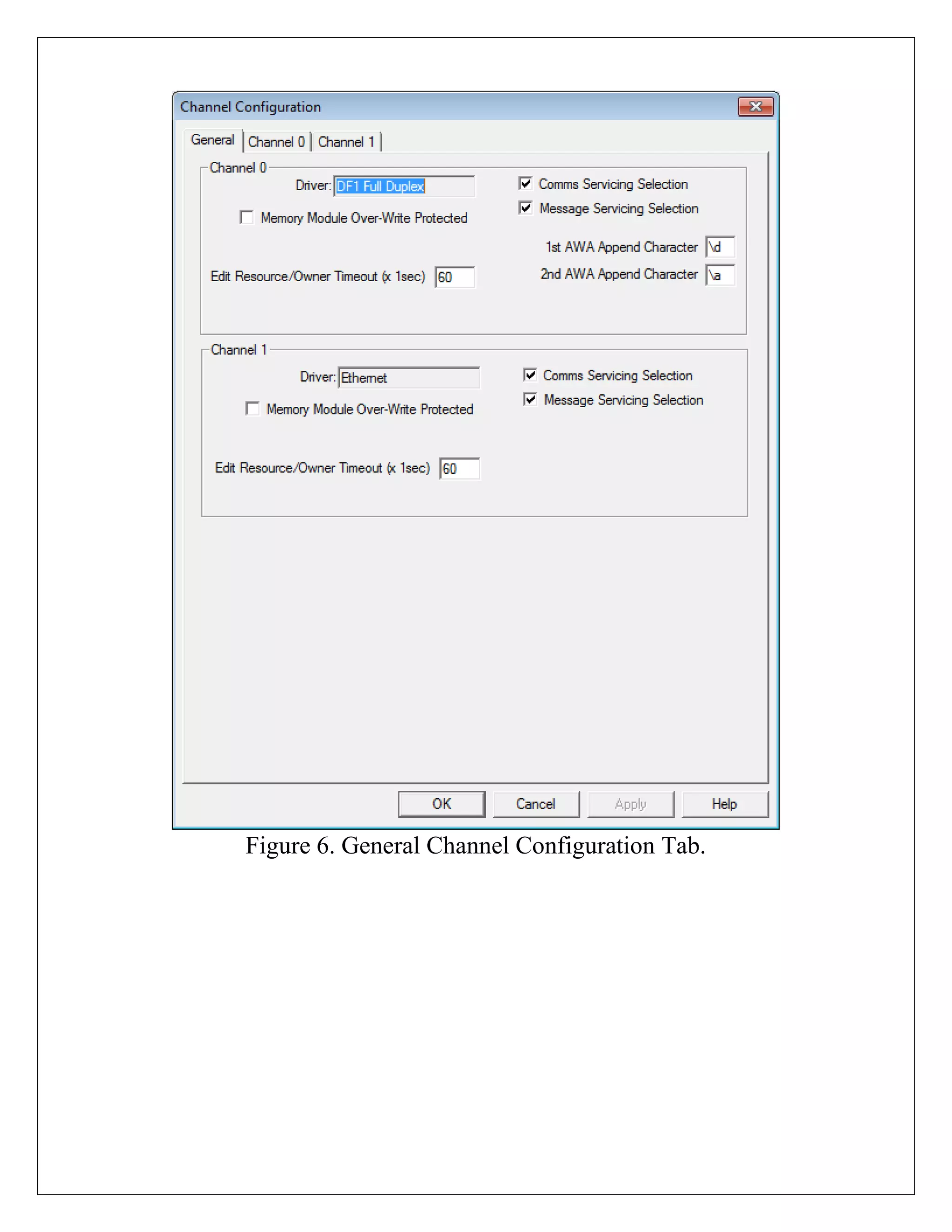
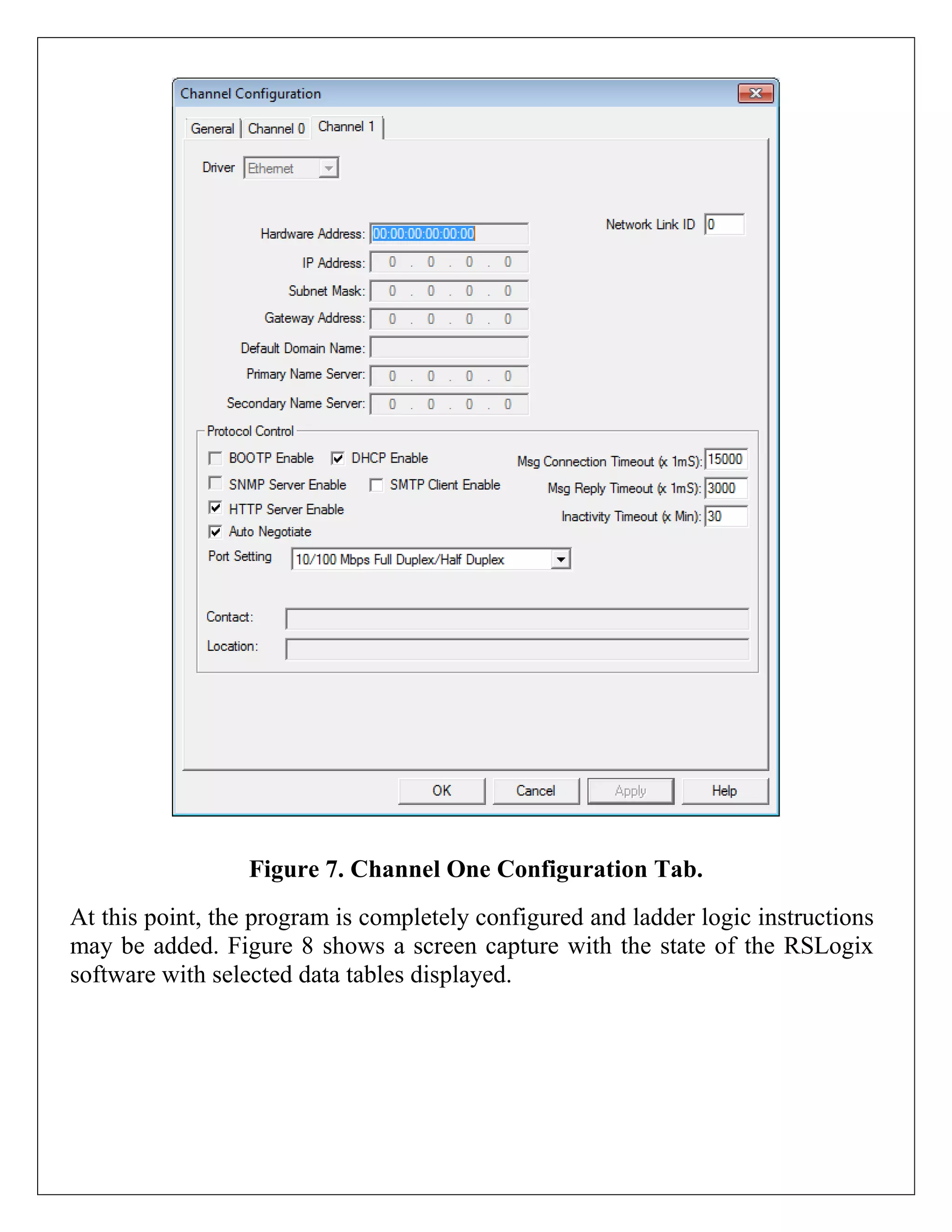
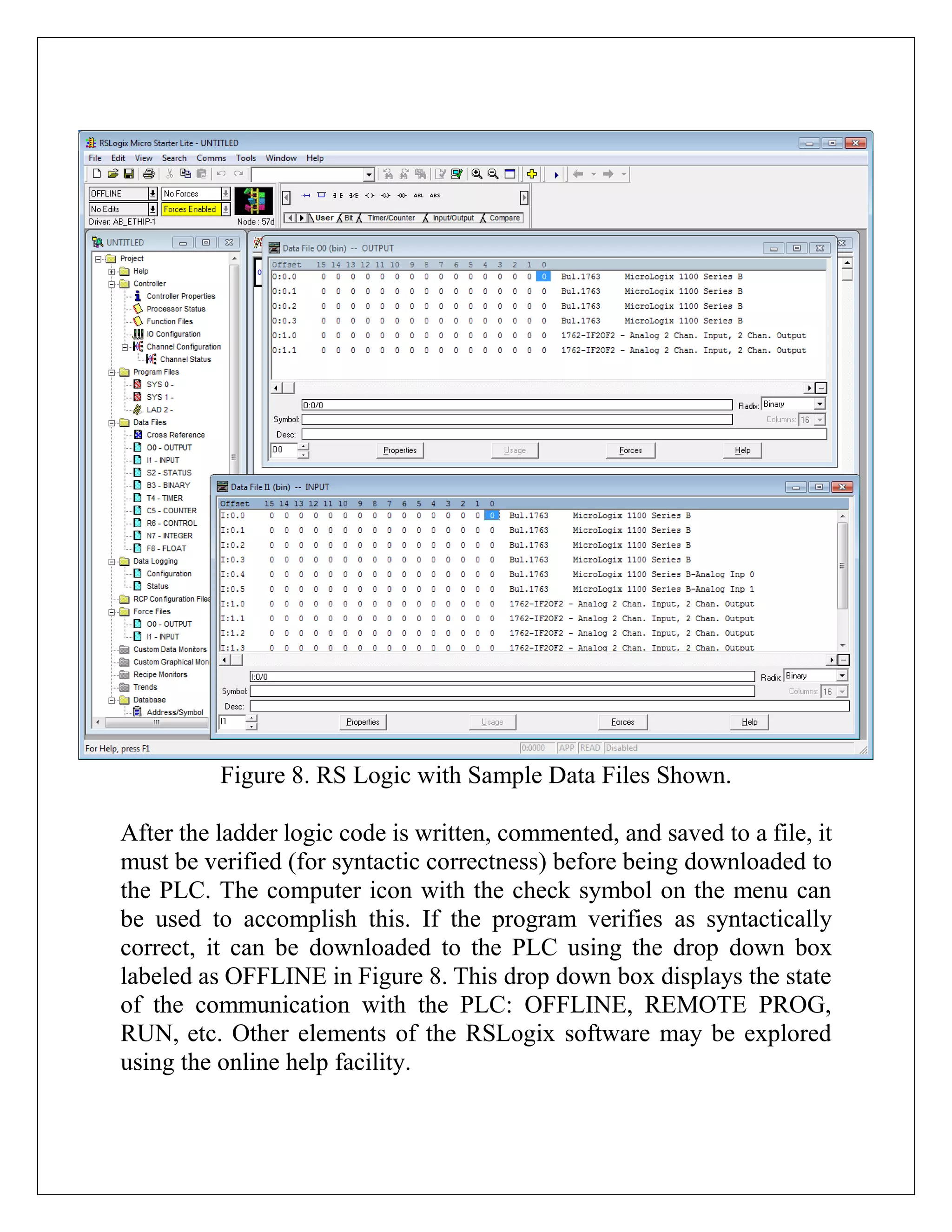
Configuration of PLC trainers includes using Relinks and RSLogix for program development, communication, and I/O module settings essential for effective operation.


![PLC Ladder Programming [Mechatronics]](https://cdn.slidesharecdn.com/ss_thumbnails/plc-ppt-snteli-200503070616-thumbnail.jpg?width=640&height=640&fit=bounds)


![ANPARA THERMAL POWER STATION[1] sangam.pdf](https://cdn.slidesharecdn.com/ss_thumbnails/anparathermalpowerstation1sangam-251121115219-9261cde4-thumbnail.jpg?width=640&height=640&fit=bounds)


