Downloaded 2,072 times
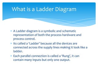
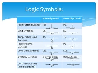
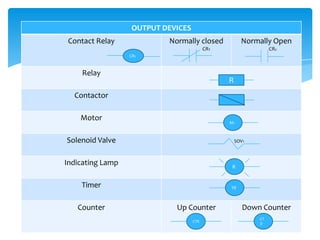
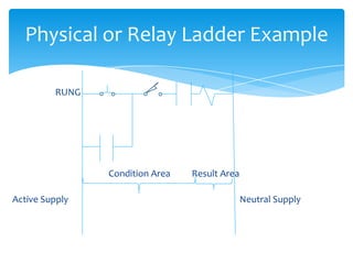
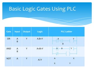
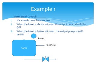
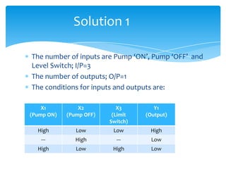
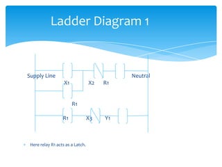
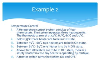
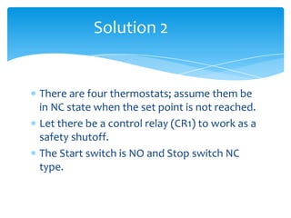
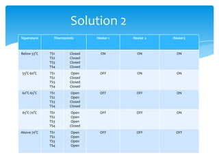
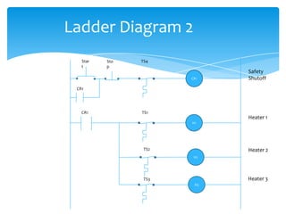


The document explains the structure and function of PLC ladder diagrams, which represent process control systems visually resembling a ladder. It details components such as inputs, outputs, and various types of switches and sensors, illustrating their roles in controlling systems like water level and temperature. Example scenarios demonstrate how to manage operations based on predefined conditions using these diagrams.


![PLC Ladder Programming [Mechatronics]](https://cdn.slidesharecdn.com/ss_thumbnails/plc-ppt-snteli-200503070616-thumbnail.jpg?width=640&height=640&fit=bounds)